Table of Contents
Advertisement
CHAPTER 1
INTRODUCTION
Chapter 1
INTRODUCTION
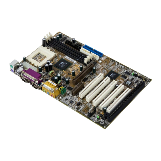
The 694 Master (MS-6309 ver 3.0) ATX mainboard is a high-performance
®
computer mainboard based on VIA
VT82C694X chipset. The 694 Master
®
TM
(MS-6309 ver 3.0) is designed for the Intel
Celeron
or Coppermine (FC-
PGA) processor for inexpensive business/personal desktop markets.
The Apollo Pro133A (VT82C694X) is a Socket-370 system logic north bridge
with the addition of 133 MHz capability for both the CPU and SDRAM
interfaces. Apollo Pro133A may be used to implement both desktop and
notebook personal computer systems from 66MHz to 133MHz based on
Socket-370. The primary features of the Apollo Pro133A-North Bridge are:
Slot-1 or Socket-370 CPU (Front Side Bus) Interface (66 / 100 / 133MHz),
DRAM Memory Interface (66 / 100 / 133MHz), AGP Bus Interface (66MHz),
PCI Bus Interface (33MHz), Mobile Power Management.
The VT82C686B PSIPC (PCI Super-I/O Integrated Peripheral Controller) is a
high integration, high performance, power-efficient, and high compatibility
device that supports Intel and non-Intel based processor to PCI bus bridge
functionality to make a complete Microsoft PC99-compliant PCI/ISA system.
1-1
Advertisement
Table of Contents

Related Manuals for MSI 694 MASTER


Summary of Contents for MSI 694 MASTER
- Page 1 CHAPTER 1 INTRODUCTION Chapter 1 INTRODUCTION The 694 Master (MS-6309 ver 3.0) ATX mainboard is a high-performance ® computer mainboard based on VIA VT82C694X chipset. The 694 Master ® (MS-6309 ver 3.0) is designed for the Intel Celeron or Coppermine (FC- PGA) processor for inexpensive business/personal desktop markets.
-
Page 2: Mainboard Features
CHAPTER 1 INTRODUCTION Mainboard Features l Socket 370 for Intel ® Celeron / Coppermine processor. l Supports 233MHz, 266MHz, 300MHz, 333MHz, 350MHz, 400MHz, 450MHz, 500MHZ, 533MHz to 1GHz. Chipset l VIA ® 694X chipset (510 BGA) - AGP 4x and PCI plus Advanced ECC Memory Controller - Support PC100/133 SDRAM, VCM technology l VIA ®... - Page 3 CHAPTER 1 INTRODUCTION On-Board IDE l An IDE controller on the VIA ® VT82C686B Chipset provides IDE HDD/ CD-ROM with PIO, Bus Master and Ultra DMA 33/66/100 operation modes. l Can connect up to four IDE devices. On-Board Peripherals l On-Board Peripherals include: - 1 floppy port supports 2 FDD with 360K, 720K, 1.2M, 1.44M and 2.88Mbytes.
-
Page 4: Mainboard Layout
PCI SLOT 1 VT1611A PCI SLOT 2 J601 VT82C686B PCI SLOT 3 JBAT1 PCI SLOT 4 JFSH1 PCI SLOT 5 BATT BIOS SYSFAN PCI SLOT 6 JGS1 JMDM1 JGL1 JRMS1 CNR1 JFP1 JSPK1 JWOL1 694 Master (MS-6309 ver 3.0) Mainboard... -
Page 5: Hardware Installation
CHAPTER 2 HARDWARE INSTALLATION Chapter 2 HARDWARE INSTALLATION Central Processing Unit: CPU ® ® The mainboard operates with Intel Celeron /Pentium III (FC-PGA) processor. The mainboard uses a CPU socket called Socket 370 for easy CPU installation. The CPU should always have a Heat Sink and a cooling fan attached to prevent overheating. - Page 6 CHAPTER 2 HARDWARE INSTALLATION • CPU Core Speed Derivation Procedure The BIOS can be used to set the CPU Host Bus Frequency Clock. CPU Clock = 66MHz Core/Bus ratio = 3.5 then CPU core speed = Host Clock x Core/Bus ratio = 66MHz x 3.5 = 233MHz...
- Page 7 CHAPTER 2 HARDWARE INSTALLATION • Fan Power Connectors: CPUFAN & SYSFAN These connectors support system cooling fan with + 12V. It supports three pin head connector. When connecting the wire to the connec- tor, always take note that the red wire is the positive and should be connected to the +12V, the black wire is Ground and should be connected to GND.
-
Page 8: Clear Cmos Jumper: Jbat1
CHAPTER 2 HARDWARE INSTALLATION Clear CMOS Jumper: JBAT1 A battery must be used to retain the mainboard configuration in CMOS RAM. Short 1-2 pins of JBAT1 to store the CMOS data. JBAT1 Clear Data Keep Data Note: You can clear CMOS by shorting 2-3 pin, while the system is off. Then, return to 1-2 pin position. -
Page 9: Memory Installation
CHAPTER 2 HARDWARE INSTALLATION Memory Installation • • • • • Memory Bank Configuration The mainboard supports a maximum memory size of 2GB (256-bit technol- ogy) SDRAM: It provides four 168-pin unbuffered DIMMs (Double In-Line Memory Module) sockets. It supports 8 MB to 512 Mbytes DIMM memory module. - Page 10 CHAPTER 2 HARDWARE INSTALLATION • • • • • Memory Installation Procedures A. How to install a DIMM Module Single Sided DIMM Double Sided DIMM 1. The DIMM slot has 2 Notch Keys “VOLT and DRAM”, so the DIMM memory module can only fit in one direction. 2.
- Page 11 CHAPTER 2 HARDWARE INSTALLATION • • • • • Memory Population Rules 1. Supports only SDRAM DIMM. 2. To operate properly, at least one 168-pin DIMM module must be in- stalled. 3. This mainboard supports Table Free memory, so memory can be installed on DIMM1, DIMM 2, DIMM 3 or DIMM4 in any order.
-
Page 12: Case Connector: Jfp1
CHAPTER 2 HARDWARE INSTALLATION Case Connector: JFP1 The Keylock (reserved), Power Switch, Reset Switch, Power LED, Speaker, and HDD LED are all connected to the JFP1 connector block. Reset Switch Power Switch Dual Single Speaker Color Color Power LED Buzzer Keylock JFP1... -
Page 13: Power Switch
CHAPTER 2 HARDWARE INSTALLATION Power Switch Connect to a 2-pin push button switch. This switch has the same feature with JRMS1. Reset Switch Reset switch is used to reboot the system rather than turning the power ON/ OFF. Avoid rebooting while the HDD LED is lit. You can connect the Reset switch from the system case to this pin. -
Page 14: Floppy Disk Connector: Fdd
CHAPTER 2 HARDWARE INSTALLATION Floppy Disk Connector: FDD The mainboard also provides a standard floppy disk connector FDD that supports 360K, 720K, 1.2M, 1.44M and 2.88M floppy disk types. This connector supports the provided floppy drive ribbon cables. 2-10... -
Page 15: Hard Disk Connectors: Ide1 & Ide2
CHAPTER 2 HARDWARE INSTALLATION Hard Disk Connectors: IDE1 & IDE2 The mainboard has a 32-bit Enhanced PCI IDE and Ultra DMA/33/66/100 Controller that provides PIO mode 0~5, Bus Master, and Ultra DMA/33/66/ 100 function. It has two HDD connectors IDE1 (primary) and IDE2 (second- ary). -
Page 16: Power Supply
CHAPTER 2 HARDWARE INSTALLATION Power Supply • • • • • ATX 20-pin Power Connector: JWR1 This connector supports the power button on-board. Using the ATX power supply, functions such as Modem Ring Wake-Up and Soft Power Off are supported by this mainboard. This power connector supports instant power on function which means that system will boot up instantly when the power connector is inserted on the board. - Page 17 CHAPTER 2 HARDWARE INSTALLATION • • • • • Remote Power On/Off Switch: JRMS1 Connect to a 2-pin push button switch. During OFF state, press once and the system turns on. During ON stage, push once and the system goes to sleep mode: pushing it more than 4 seconds will change its status from ON to OFF.
-
Page 18: Irda Infrared Module Connector: J4
CHAPTER 2 HARDWARE INSTALLATION IrDA Infrared Module Connector: J4 The mainboard provides one infrared (J4) connector for IR modules. This connector is for optional wireless transmitting and receiving infrared module. You should configure the setting through the BIOS setup to use the IR function. - Page 19 CHAPTER 2 HARDWARE INSTALLATION Serial Port Connectors: COM A and COM B The mainboard provides two 9-pin male DIN connectors for serial port COM A & COM B. These port are 16550A high speed communication port that send/receive 16 bytes FIFOs. You can attach a mouse or a modem cable directly into this connector.
-
Page 20: Parallel Port Connector: Lpt1
CHAPTER 2 HARDWARE INSTALLATION Parallel Port Connector: LPT1 The mainboard provides a 25 pin female centronic connector for LPT. A parallel port is a standard printer port that also supports Enhanced Parallel Port (EPP) and Extended capabilities Parallel Port (ECP). See connector and pin definition below: Parallel Port (25-pin Female) LPT 1... -
Page 21: Mouse Connector: Jkbms1
CHAPTER 2 HARDWARE INSTALLATION Mouse Connector: JKBMS1 ® The mainboard provides a standard PS/2 mouse mini DIN connector for ® ® attaching a PS/2 mouse. You can plug a PS/2 mouse directly into this connector. The connector location and pin definition are shown below: Pin5 Mouse Clock Pin6... -
Page 22: Joystick/Midi Connectors
CHAPTER 2 HARDWARE INSTALLATION Joystick/Midi Connectors You can connect a joystick or game pad to this connector. Joystick/MIDI Audio Port Connectors Line Out is a connector for Speakers or Headphones. Line In is used for external CD player, Tape player, or other audio devices. Mic is a connector for the microphones. -
Page 23: Usb Connectors
CHAPTER 2 HARDWARE INSTALLATION USB Connectors The mainboard provides a UHCI (Universal Host Controller Interface) Universal Serial Bus root for attaching USB devices like: keyboard, mouse and other USB devices. You can plug the USB device directly to this connector. USB Port 2 1 2 3 4 USB Port 1... - Page 24 CHAPTER 2 HARDWARE INSTALLATION Wake-Up on LAN Connector: JWOL1 The JWOL1 connector is use with LAN add-on cards that supports Wake Up on LAN function. To use this function, set the “Wake-Up on LAN” to enable located at the BIOS Power Management Setup. JWOL1 SIGNAL 5VSB...
-
Page 25: Modem Wake Up Connector: Jmdm1
CHAPTER 2 HARDWARE INSTALLATION Modem Wake Up Connector: JMDM1 The JMDM1 connector is used for Modem add-on card that supports the Modem Wake Up function. JMDM1 SIGNAL MDM_WAKEUP 5VSB Note: Modem wake-up signal is active “low”. Note: To be able to use this function, you need a power supply that provide enough power for this feature. -
Page 26: Power Saving Switch Connector: Jgs1
CHAPTER 2 HARDWARE INSTALLATION Power Saving Switch Connector: JGS1 Attach a power saving switch to JGS1. When the switch is pressed, the system immediately goes into suspend mode. Press any key and the system wakes up. JGS1 2-22... -
Page 27: Power Saving Led Connector: Jgl1
CHAPTER 2 HARDWARE INSTALLATION Power Saving LED Connector: JGL1 JGL1 can be connected with two-color LED. There are two types of LED that can be use: 3-pin LED or 2-pin LED. When the 2-pin LED is con- nected to JGL1, the light will turn green, when the system is On. During sleep mode, the 2-pin LED will change its color from Green to Orange. - Page 28 CHAPTER 2 HARDWARE INSTALLATION CPU Termination Voltage Jumper: JVTT (reserved) This jumper is a reserved function for future Coppermine CPU. JVTT Function JVTT For Celeron For Coppermine 2-24...
- Page 29 CHAPTER 2 HARDWARE INSTALLATION CNR1 (Communication Network Riser) The Communication Network Riser specification is an open industry- standard specification that defines a hardware scalable Original Equipment Manufacturer (OEM) mainboard riser board and interface, which supports audio and modem only. CNR1 2-25...
-
Page 30: Diagnostic Led
CHAPTER 2 HARDWARE INSTALLATION Diagnostic LED The mainboard provides a Special Diagnostic LED for users to be aware of their mainboard conditions. The LED helps user determine the problem of the mainboard. Refer to chapter 2-29 for Diagnostic LED & Smart D-LED voice function table. - Page 31 CHAPTER 2 HARDWARE INSTALLATION Smart D-LED Voice Speaker Select Output Jumper: JSPK The mainboard provides a Smart D-LED voice function which help users be aware of their mainboard conditions. This jumper will enable the Smart D- LED voice through the case speaker/buzzer and transferred it to the audio speaker.
- Page 32 CHAPTER 2 HARDWARE INSTALLATION Smart D-LED Voice Mode Tool: J601 This jumper works through a recorded voice which helps user identify the cause of any possible failure. The recorded voice can either be in English or Chinese language. Refer to chapter 2-29 for Diagnostic LED & Smart D-LED voice function table.
- Page 33 CHAPTER 2 HARDWARE INSTALLATION Diagnostic LED & Smart D-LED Voice Function Table D-LED 1 2 3 4 DESCRIPTION POSSIBLE PROBLEM/VOICE CONTEXT 0 0 0 0 System Power ON The processor might be damaged or not installed properly** This will start the BIOS Initialization 1 0 0 0 Early Chipset Initialization Please check local vendor**...
- Page 34 CHAPTER 2 HARDWARE INSTALLATION CD-In Connector: JCD This connector is used for CD-ROM audio connector. 2-30...
- Page 35 CHAPTER 2 HARDWARE INSTALLATION AUX Line In Connector: JAUX This connector is for DVD Add on Card with Line In connector. R GND L JAUX 2-31...
- Page 36 CHAPTER 2 HARDWARE INSTALLATION Modem-In: JPH This connector is for Modem with internal voice connector. Mono_Out GND Phone_In Mono_Out is connected to the Modem Speaker Out connector. Phone_In is connected to the Modem Microphone In connector. 2-32...
-
Page 37: Software Support
CHAPTER 2 HARDWARE INSTALLATION IEEE 1394 Connector (optional) The IEEE 1394 high-speed serial bus complements USB by providing enhanced PC connectivity for a wide range of devices, including consumer electronics audio/video (A/V) appliances, storage peripherals, other PCs, and portable devices. Software Support ®... - Page 38 CHAPTER 2 HARDWARE INSTALLATION BIOS Flash Jumper: JFSH1 This jumper is used to locked/unlocked BIOS Flash. The BIOS flash jumper should be unlock when flashing/programming the BIOS. JFSH1 BIOS Flash BIOS Flash Locked Unlocked 2-34...
- Page 39 CHAPTER 2 HARDWARE INSTALLATION USB Front Connector: USB2 The mainboard provides a front Universal Serial Bus connector. This is an optional USB connector for Front Panel. USB2 Description Description USBD2+ USBD3- USBD2- USBD3+ 2-35...
- Page 40 ® Chapter 3 ® BIOS USER’S GUIDE The system configuration information and chipset register information is stored in the CMOS RAM. This information is retained by a battery when the power is off. Enter the BIOS setup (if needed) to modify this information. The following pages will describe how to enter BIOS setup, and all about options.
-
Page 41: Enter Bios Setup
® Enter BIOS Setup ® Enter the AMI setup Program’s Main Menu as follows: 1. Turn on or reboot the system. The following screen appears with a series of diagnostic check. AMIBIOS (C) 1999 American Megatrends Inc. A6309 VXXX XXXXXX Hit <DEL>... - Page 42 ® AMIBIOS SIMPLE SETUP UTILITIES - VERSION 1.21f (C) 1998 American Megatrends, Inc. All Rights Reserved Integrated Peripherals Standard CMOS Setup Hardware Monitor Setup BIOS Features Setup Supervisor Password Chipset Features Setup User Password Power Management Setup IDE HDD Auto Detection PNP/PCI Configuration Save and Exit Setup Load BIOS Defaults...
-
Page 43: Standard Cmos Setup
® Standard CMOS Setup 1. Press <ENTER> on “Standard CMOS Setup” of the main menu screen . AMIBIOS SETUP - STANDARD CMOS SETUP (C)1999 American Megatrends,Inc.All Rights Reserved Date (mm/dd/yyyy): Fri Oct 29, 1999 Time (hh/mm/ss): 17:09:25 Type Size CYLS HEAD PRECOMP LANDZ... -
Page 44: Bios Features Setup
® BIOS Features Setup 1. Press <ENTER> on “BIOS Features Setup” of the main menu screen. AMIBIOS SETUP - BIOS FEATURES SETUP (C) 1999 American Megatrends, Inc. All Rights Reserved D800, 16K Shadow :Disabled Quick Boot :Enabled DC00, 16K Shadow :Disabled 1st Boot Device :Floppy... -
Page 45: Quick Boot
The system will boot from the SCSI. Network The system will boot from the Network drive. Initial Display Mode Set this option to BIOS mode for normal boot-up. Silent mode to show the MSI logo during system boot-up. The settings are BIOS or Silent. -
Page 46: Password Check
® S.M.A.R.T. for Hard Disks This option sets the SMART Function for the hard disk. The hard disk need to have SMART function for this feature to work. Boot up Num Lock ® When this option is set to Off, AMI BIOS turns off the Num Lock key when the system is powered on. -
Page 47: System Bios Cacheable
® ® Boot To OS/2 > 64MB Set this option to Enabled to permit the BIOS to run properly, if ® OS/2 is to be used with > 64MB of DRAM. The settings are Enabled or Disabled. The Setup and BIOS default settings are Disabled. L2 Cache This option enables the Level 2 Cache memory. -
Page 48: Chipset Features Setup
® Chipset Features Setup 1. Press <ENTER> on “Chipset Features Setup” of the main menu screen. AMIBIOS SETUP - CHIPSET FEATURES SETUP (C) 1999 American Megatrends, Inc. All Rights Reserved Set SDRAM Timing by SPD :Disabled DRAM Frequency :HCLK SDRAM CAS# Latency DRAM Integrity Mode :Disabled CPU In Order Queue... -
Page 49: Dram Frequency
® Description of the item on screen follows: Set SDRAM Timing By SPD Choose Enabled, will automatically configure the DRAM Timing depending on the “DRAM Speed” selection. Choose Disabled, to customize the setup. DRAM Frequency This item specify the DRAM frequency of the system. The settings are HCLK-33 (FSB-33), HCLK (FSB) and HCLK+33 (FSB+33). -
Page 50: Agp Aperture Size
® AGP Aperture Size This option determines the effective size of the graphics aperture used in the particular MCM configuration. The AGP aperture is memory - mapped, while graphics data structure can reside in a graphics aperture. The aperture range should be programmed as not cacheable in the processor cache,accesses with the aperture range are forwarded to the main memory, then MCM will translate the original issued address via a translation table that is maintained on the main memory. -
Page 51: Power Management Setup
® Power Management Setup 1. Press <ENTER> on “Power Management Setup” of the main menu screen. AMIBIOS SETUP - POWER MANAGEMENT SETUP (C) 1999 American Megatrends, Inc. All Rights Reserved Restore on AC/Power Loss :Last State IPCA Function :Yes Resume On Ring/LAN :Enabled Green PC LED Status :Dual Color... -
Page 52: Video Power Down Mode
® Description of the item on screen follows: IPCA Function This item allows you to Enabled/Disabled the Advanced Configura- tion and Power Management (ACPI). The settings are Yes and No. Green PC LED Status This item determines which state the Power LED will use. The settings are Blinking, Dual, and Single. -
Page 53: Throttle Slow Clock Ratio
® Throttle Slow Clock Ratio This option specifies the speed at which the system clock runs in power saving states. The settings are expressed as ratio between the normal CPU clock speed and the CPU clock speed when the computer is in the power-conserving state. -
Page 54: Restore On Ac Power Loss
® Restore on AC/Power Loss The settings are power on, power off or last state. During power on, after every AC power loss, the system will be turned on. During last status, after every AC power off, whatever the system status, it will be the same when the AC power returns. -
Page 55: Pnp/Pci Configuration
® PNP/PCI Configuration 1. Press <ENTER> on “PNP/PCI Configuration” of the main menu screen. AMIBIOS SETUP - PNP/PCI CONFIGURATION (C) 1999 American Megatrends, Inc. All Rights Reserved PnP Aware O/S Clear NVRAM PCI Latency Timer Primary Graphics Adapter :PCI PCI VGA Palette Snoop :Disabled DMA Channel 0 :PnP... -
Page 56: Pci Latency Timer
® Description of the item on screen follows: Plug and Play Aware O/S Set this option to Yes if the operating system in this computer is aware of and follows the Plug and Play specification. The settings are Yes or No. -
Page 57: Dma Channel
® DMA Channel 0/1/3/5/6/7 These options specify the bus that the specified DMA channel is used. These options allow you to reserve DMAs for legacy ISA adapter cards. ® These options determine if AMI BIOS should remove a DMA from the available DMAs passed to devices that are configurable by the system BIOS. -
Page 58: Integrated Peripherals
® Integrated Peripherals 1. Press <ENTER> on “Integrated Peripherals” of the main menu screen. AMIBIOS SETUP - INTEGRATED PERIPHERALS (C) 1999 American Megatrends, Inc. All Rights Reserved Onchip IDE :Both Floppy Controller :Auto Serial Port A :Auto Serial Port B :Auto Serial Port B Mode :Normal... - Page 59 ® Description of the item on screen follows: Onchip IDE This item allows you to set the Onchip IDE controller. Floppy Controller This item allows you to Enabled or Disabled the onboard FDC. Choose Auto to allow the BIOS to automatically detect the device. The default setting is Auto.
-
Page 60: Parallel Port Irq
® Parallel Port IRQ If the onboard parallel mode is not on auto mode, the user can select the interrupt line for onboard parallel port. We suggest that the user select the interrupt for the onboard parallel port as shown below: Parallel Port IRQ Onboard parallel port set at LPT1(378H) -
Page 61: Hardware Monitor Setup
® Hardware Monitor Setup 1. Press <ENTER> on “Hardware Monitor Setup” of the main menu screen. AMIBIOS SETUP - Hardware Monitor Setup (C) 1999 American Megatrends, Inc. All Rights Reserved Spread Spectrum :Enabled CPU FSB Clock (MHz) :Auto CPU Ratio Selection :3.0X CPU Vcore Selection (V) :Auto... -
Page 62: Spread Spectrum
® Description of the item on screen follows: Spread Spectrum This item allows you to select the clock generator Spread Spectrum function. When overclocking the processor, always set this item to Disa- bled. The default setting is Enabled. CPU FSB Clock (Mhz) Check your processor and set this function accordingly. -
Page 63: Ide Hdd Auto Detection
® IDE HDD Auto Detection You can use this utility to automatically detect the characteristics of most hard drives. AMIBIOS SETUP - STANDARD CMOS SETUP (C)1999 American Megatrends,Inc.All Rights Reserved Date (mm/dd/yyyy): Fri Oct 29, 1999 Time (hh/mm/ss): 17:09:25 Type Size CYLS HEAD... -
Page 64: Supervisor/User Password
® Supervisor/User Password This Main Menu item lets you configure the system so that a password is required each time the system boots or an attempt is made to enter the Setup program. Supervisor Password allows you to change all CMOS settings but the User Password setting doesn’t have this function. -
Page 65: Audio Features
Chapter 4 VIA CHIPSET DRIVER Overview The 694 Master (MS-6309 ver 3.0) is paired with the VIA VT82C686B south bridge. Highly advanced, the south bridge combines an integrated 2D/3D engine with DVD hardware acceleration, AC-97 audio support for SoundBlaster Pro and FM synthesis legacy audio. - Page 66 CHAPTER 4 VIA CHIPSET DRIVER Driver Setup & Usage Procedures for Windows ® Insert the CD-title into your CD-ROM drive. The CD will auto-run and will display the four icons in the monitor “VIA Chipset Drivers”, “VIA AC97 PCI Sound Drivers” and “Download VIA Drivers”. In order to install the drivers correctly, you must install the “Via Chipset Drivers”...
- Page 67 CHAPTER 4 VIA CHIPSET DRIVER Step 8: The setup program will let you choose between “Install VIA Chipset Functions Registry” or “Uninstall VIA Chipset Functions Registry”. Please select “Install VIA Chipset Functions Registry” and then click “Next”. Step 9: The setup program will let you choose between “Install VIA IRQ Routing Miniport Driver”...
- Page 68 CHAPTER 4 VIA CHIPSET DRIVER VIA AC97 PCI Sound Drivers installation procedure: Step 1: Insert the provided CD_ROM disk into the CD-ROM drive. Step 2: Look for the CD_ROM drive, double click on the CD_ROM icon. This will show the setup screen. Step 3: Click on “VIA AC97 PCI Sound Drivers”...
-
Page 69: Windows Nt
CHAPTER 4 VIA CHIPSET DRIVER Windows NT 4.0 ® ® Install Windows NT 4.0 Service Pack 6 or the latest version before installing the VIA drivers. Insert the CD-title in the CD-ROM drive. The CD will auto-run and will display four icons on the screen “VIA Chipset Drivers”, “VIA AC97 PCI Sound Drivers”and “Download VIA Drivers”. - Page 70 CHAPTER 4 VIA CHIPSET DRIVER VIA AC97 PCI Sound Drivers Installation Procedure: Step 1: Insert the provided CD_ROM disk into the CD-ROM drive. Step 2: Look for the CD_ROM drive, double click on the CD_ROM icon. This will show the setup screen. Step 3: Click on “VIA AC97 PCI Sound Drivers”...
Need help?
Do you have a question about the 694 MASTER and is the answer not in the manual?
Questions and answers