
Related Manuals for MSI 645 Ultra-C


Summary of Contents for MSI 645 Ultra-C
- Page 1 645 Ultra-C MICRO-STAR INTERNATIONAL MS-6547 (v2.X) ATX Mainboard Version 2.1 G52-MA00627...
- Page 2 FCC-B Radio Frequency Interference Statement Notice 1 Notice 2 VOIR LA NOTICE D’INSTALLATION AVANT DE RACCORDER AU RESEAU. Micro-Star International MS-6547 Tested to comply with FCC Standard For Home or Office Use...
- Page 3 Edition Copyright Notice MICRO-STAR INTERNATIONAL Trademarks ® ® ® ® ® ® ® Revision History Revision Revision History Date...
- Page 4 Safety Instructions CAUTION:...
- Page 5 CONTENTS Chapter 1. Getting Started ................ 1-1 Chapter 2. Hardware Setup ............... 2-1...
- Page 6 Chapter 3. BIOS Setup ................3-1...
- Page 7 Glossary ....................G-1...
-
Page 8: Getting Started
Getting Started Chapter 1. Getting Started Getting Started ® ® TOPICS Mainboard Specification Mainboard Layout Quick Components Guide MSI Special Features... -
Page 9: Mainboard Specification
Chapter 1 Mainboard Specification ® ® Chipset ® ® ® Main Memory Slots On-Board IDE... - Page 10 Getting Started On-Board Peripherals Audio BIOS Dimension Mounting Others...
-
Page 11: Mainboard Layout
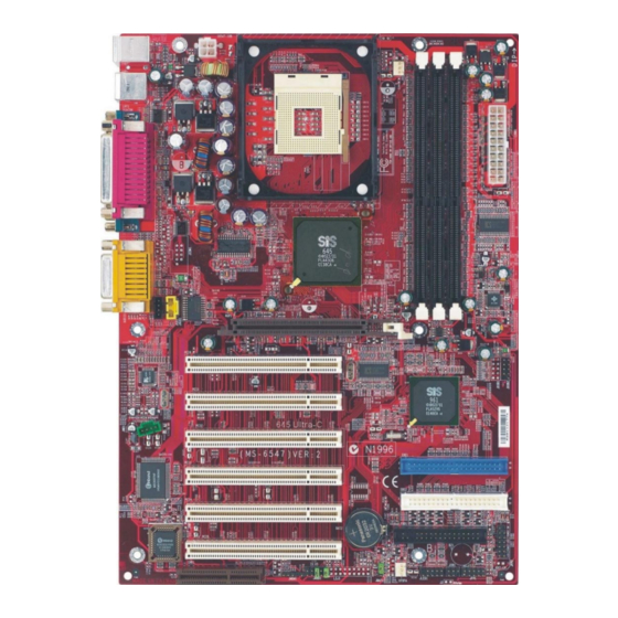
Chapter 1 Mainboard Layout Top : mouse Bottom: keyboard JPW1 CPUFA ports Top : Parallel Port Bottom: COM A COM B Top : Game port Bottom: Line-Out Line-In JAUX1 AGP Slot JCD1 JUSB1 PCI Slot 6 JUSB2 PCI Slot 1 JMD1 PCI Slot 2 IDE 1... -
Page 12: Quick Components Guide
Getting Started Quick Components Guide... -
Page 13: Msi Special Features
Chapter 1 MSI Special Features Fuzzy Logic™ 4 Fuzzy Logic™ 4 Apply Turbo Save Auto Turbo Default Features: provides information about the mainboard, BIOS and OS Note: To adjust the options under CPU Speed and Voltage, use the right and left arrow keys to select the desired value and then click... - Page 14 Getting Started Live BIOS™/Live Driver™ l l l l l Live BIOS – Updates the BIOS online. l l l l l Live Driver – Updates the drivers online. l l l l l Live VGA BIOS – Updates the VGA BIOS online. l l l l l Live VGA Driver –...
- Page 15 Chapter 1 D-Bracket™ (optional) D-Bracket™ Green D-Bracket Description System Power ON - The D-LED will hang here if the processor is damaged or not installed properly. Early Chipset Initialization Memory Detection Test - Testing onboard memory size. The D-LED will hang if the memory module is damaged or not installed properly.
- Page 16 Getting Started D-Bracket Description Processor Initialization - This will show information regarding the processor (like brand name, system bus, etc…) Testing RTC (Real Time Clock) Initializing Video Interface - This will start detecting CPU clock, checking type of video onboard. Then, detect and initialize the video adapter. BIOS Sign On - This will start showing information about logo, processor brand name, etc….
-
Page 17: Hardware Setup
Hardware Setup Chapter 2. Hardware Setup Hardware Setup TOPICS Central Processing Unit: CPU Memory Installation Power Supply Back Panel Connectors 2-12 Jumpers 2-21 Slots 2-22... -
Page 18: Central Processing Unit (Cpu)
Chapter 2 Central Processing Unit: CPU ® ® make sure the CPU has a heat sink and a cooling fan attached on the top to prevent overheating. Open Lever Sliding Plate Gold Arrow Close Lever Overheating will seriously damage the CPU and system, always make sure the cooling fan can work properly to protect the CPU from overheating. - Page 19 Hardware Setup retention mechanism levers...
- Page 20 Chapter 2 fan power cable then Overclocking This motherboard is designed to support overclocking. However, please make sure your components are able to WARNING! tolerate such abnormal setting, while doing overclocking. Any attempt to operate beyond product specifications is not recommended.
- Page 21 Hardware Setup Memory DDR DIMM Slots (DDR 1~3) PC2700 PC2100 PC1600 (DDR333) (DDR266) (DDR200) Clock 166MHz 133MHz 100MHz Peak Bandwidth 2666MB/s 2133MB/s 1600MB/s...
- Page 22 Chapter 2 S l o t M e m o r y M o d u l e T o t a l M e m o r y S l o t 1 6 4 M B , 1 2 8 M B , 6 4 M B ~ 1 G B ( B a n k 0 &...
-
Page 23: Power Supply
Hardware Setup Power Supply instant power on JPW1 CONN1 CONN1 Pin Definition SIGNAL SIGNAL JPW1 Pin Definition SIGNAL... -
Page 24: Back Panel
Chapter 2 Back Panel Parallel Midi/Joystick M ous e Keyboard USB COM A COM B L-out L-in MIC ® ® ® Pin Definition SIGNAL DESCRIPTION PS/2 Mouse (6-pin Female) - Page 25 Hardware Setup ® ® ® Pin Definition SIGNAL DESCRIPTION PS/2 Keyboard (6-pin Female) USB Port Description SIGNAL DESCRIPTION 1 2 3 4 5 6 7 8 USB Ports...
- Page 26 Chapter 2 Pin Definition 1 2 3 4 5 SIGNAL DESCRIPTION 6 7 8 9 9-Pin Male DIN Connectors Line Out Line In 1/8” Stereo Audio Connectors Line Out Line In 2-10...
- Page 27 Hardware Setup Pin Definition SIGNAL DESCRIPTION 2-11...
- Page 28 Chapter 2 Connectors FDD 1 2-12...
- Page 29 Hardware Setup IDE 1 IDE 2 IDE1 IDE2 If you install two hard disks on cable, you must configure the second drive to Slave mode by setting its jumper. Refer to the hard disk documentation supplied by hard disk vendors for jumper setting instructions.
- Page 30 Chapter 2 JCD1 JAUX1 JMD1 Phone_In Mono_Out 2-14...
- Page 31 Hardware Setup SENSOR +12V CPUFA SENSOR +12V SYSFA Note: 1. Always consult the vendor for proper CPU cooling fan. 2. CPU Fan supports the fan control. You can install the PC Alert utility that will automatically control the CPU Fan speed accord- ing to the actual CPU temperature.
- Page 32 Chapter 2 MDM_WAKEUP 5VSB JMDM1 ® JIR1 Pin Definition Signal JIR1 2-16...
- Page 33 Hardware Setup ® JFP2 (Intel spec) JFP1 (Intel spec) JFP2 Pin Definition Signal Signal JFP1 Switch/LED Front Panel Electrical Connection SIGNAL DESCRIPTION 2-17...
- Page 34 Chapter 2 ® JAUD1 Pin Definition SIGNAL DESCRIPTION CAUTION!!! If you don’t want to connect to the front audio header, pins 5 and 6, 9 and 10 have to be shorted by jumper caps in order to have signal output directed to the rear audio ports.
- Page 35 Hardware Setup ® JUSB1/JUSB2 (Intel spec) JUSB1/JUSB2 Pin Definition Description Description 2-19...
- Page 36 Chapter 2 Chapter 1. D- Bracket™ JLED1 Connected to JLED1 Connected to JUSB1 or JUSB2 D-Bracket™ 2-20...
- Page 37 Hardware Setup Jumpers Keep CMOS Clear CMOS JBAT1 You can clear CMOS by shorting 2-3 pin while the system is off. Then return to 1-2 pin position. Avoid clearing the CMOS while the system is on; it will WARNING! damage the mainboard. 2-21...
- Page 38 Chapter 2 Slots AGP Slot PCI Slots CNR Slot 2-22...
- Page 39 Hardware Setup Order 1 Order 2 Order 3 Order 4 PCI Slot 1 INT C# INT D# INT A# INT B# PCI Slot 2 INT A# INT B# INT C# INT D# PCI Slot 3 INT B# INT C# INT D# INT A# PCI Slot 4 INT C#...
-
Page 40: Ami Bios Setup
BIOS Setup ® Chapter 3. AMI BIOS Setup ® BIOS Setup ® ®... -
Page 41: Entering Setup
Chapter 3 Entering Setup DEL:Setup F11:Boot Menu F12:Network boot TAB:Logo Selecting the First Boot Device Select First Boot Device Floppy : 1st Floppy IDE-0 : IBM-DTLA-307038 CDROM : ATAPI CD-ROM DRIVE 40X M [Up/Dn] Select [RETURN] Boot [ESC] cancel... -
Page 42: Control Keys
BIOS Setup ® Control Keys Move to the previous item <↑> Move to the next item <↓> Move to the item in the left hand <←> <→> Move to the item in the right hand <Enter> Select the item <Esc> Jumps to the Exit menu or returns to the main menu from a submenu <+/PU>... -
Page 43: The Main Menu
Chapter 3 The Main Menu ®... - Page 44 BIOS Setup ®...
-
Page 45: Standard Cmos Features
Chapter 3 Standard CMOS Features... - Page 46 BIOS Setup ® Note:...
-
Page 47: Advanced Bios Features
Chapter 3 Advanced BIOS Features... - Page 48 BIOS Setup ® Note...
- Page 49 Chapter 3 ® ® 3-10...
- Page 50 BIOS Setup ® 3-11...
-
Page 51: Advanced Chipset Features
Chapter 3 Advanced Chipset Features Note: 3-12... - Page 52 BIOS Setup ® 3-13...
-
Page 53: Power Management Setup
Chapter 3 Power Management Setup 3-14... - Page 54 BIOS Setup ® 3-15...
- Page 55 Chapter 3 Note 1: Note 2 Note 3 3-16...
- Page 56 BIOS Setup ® 3-17...
-
Page 57: Pnp/Pci Configurations
Chapter 3 PNP/PCI Configurations 3-18... - Page 58 BIOS Setup ® Disabled Data read or written by the CPU is only directed to the PCI VGA device’s palette registers. Enabled Data read or written by the CPU is directed to both the PCI VGA device’s palette registers and the ISA VGA device’s pal- ette registers, permitting the palette registers of both VGA devices to be identical.
- Page 59 Chapter 3 3-20...
-
Page 60: Integrated Peripherals
BIOS Setup ® Integrated Peripherals 3-21... - Page 61 Chapter 3 3-22...
- Page 62 BIOS Setup ® 3-23...
- Page 63 Chapter 3 3-24...
-
Page 64: Pc Health Status
BIOS Setup ® PC Health Status 3-25... -
Page 65: Frequency/Voltage Control
Chapter 3 Frequency/Voltage Control CPU FSB Clock Setting Options 100MHz 1:1, 3:4, 3:5, 2:3, By SPD 101~132MHz 1:1, 3:4, 3:5, 2:3 133~160MHz 4:3, 1:1, 4:5, By SPD 161~200MHz Auto 3-26... - Page 66 BIOS Setup ® 3-27...
-
Page 67: Set Supervisor/User Password
Chapter 3 Set Supervisor/User Password Note: 3-28... -
Page 68: Load High Performance/Bios Setup Defaults
BIOS Setup ® Load High Performance/BIOS Setup Defaults The Load High Performance Defaults option is for power or overclocking users only. Use of high performance defaults will tighten most timings to increase the system performance. Therefore, WARNING! a high-end system configuration is a must, which means you need high-quality VGA adapter, RAM and so on. - Page 69 Glossary Glossary Glossary ACPI Advanced Configuration & Power Interface AGP Accelerated Graphics Port BIOS basic input/output system Cache Chipset...
- Page 70 Glossary CMOS complementary metal-oxide semiconductor DIMM dual in-line memory module SIMM (single in-line memory module) DRAM Dynamic RAM Dynamic RAM (DRAM) Memory Technologies Peak Type First Used Clock Rate Bus* Width Volts Bandwidth FPM (60,70ns) 1990 25MHz 64 bits 200 MBps EDO (50,60,70ns) 1994 40MHz...
- Page 71 Glossary ECC Memory error correcting code memory IDE Integrated Drive Electronics IEEE 1394 FireWire iLink IrDA Infrared Data Association LAN local area network LED light emitting diode LPT line printer terminal...
- Page 72 Glossary PCI Peripheral Component Interconnect PnP Plug and Play POST Power On Self Test PS/2 Port USB universal serial bus Virus...
Need help?
Do you have a question about the 645 Ultra-C and is the answer not in the manual?
Questions and answers