
Related Manuals for MSI 645 Ultra


Summary of Contents for MSI 645 Ultra
- Page 1 645 Ultra MICRO-STAR INTERNATIONAL MS-6547 (v1.X) ATX Mainboard Version 1.0 G52-MA00481...
- Page 2 Manual Rev: 1.0 Release Date: Oct. 2001 FCC-B Radio Frequency Interference Statement This equipment has been tested and found to comply with the limits for a class B digital device, pursuant to part 15 of the FCC rules. These limits are designed to provide reasonable protection against harmful interference when the equip- ment is operated in a commercial environment.
-
Page 3: Revision History
Edition Oct. 2001 Copyright Notice The material in this document is the intellectual property of MICRO- STAR INTERNATIONAL. We take every care in the preparation of this document, but no guarantee is given as to the correctness of its contents. Our products are under continual improvement and we re- serve the right to make changes without notice. -
Page 4: Safety Instructions
Safety Instructions Always read the safety instructions carefully. Keep this User’s Manual for future reference. Keep this equipment away from humidity. Lay this equipment on a reliable flat surface before setting it up. The openings on the enclosure are for air convection hence protects the equipment from overheating. -
Page 5: Table Of Contents
Chapter 1. Getting Started ................ 1-1 Mainboard Specification ..............1-2 Mainboard Layout ................1-4 Quick Components Guide ..............1-5 MSI Special Features ................1-6 T.O.P Tech™ ................. 1-6 PC Alert™ III ................. 1-7 Fuzzy Logic™ III ................1-8 Live BIOS™/Live Driver™ ............1-8 D-Bracket™... - Page 6 Audio Port Connectors ............... 2-10 Parallel Port Connector: LPT1 ............2-11 Connectors ..................2-12 Floppy Disk Drive Connector: FDD1 ........... 2-12 Hard Disk Connectors: IDE1 & IDE2 ........... 2-13 CD-In Connector: JCD1 ............... 2-14 Aux Line-In Connector: JAUX1 ..........2-14 Modem-In Connector: JMD1 ............
- Page 7 Advanced BIOS Features ..............3-8 Advanced Chipset Features ............... 3-11 Power Management Features ............. 3-13 PNP/PCI Configurations ..............3-16 Integrated Peripherals ................ 3-19 PC Health Status ................3-22 Frequency/Voltage Control ..............3-23 Supervisor/User Password ..............3-25 Load High Performance/BIOS Setup Defaults ........3-26 Glossary ....................
-
Page 8: Chapter 1. Getting Started
Chapter 1. Getting Started Getting Started Thank you for purchasing the 645 Ultra (MS-6547 v1.X) ATX mainboard. The 645 Ultra is a superior computer mainboard based on SiS645 & SiS961 chipsets for optimal system efficiency. Designed to fit the advanced Intel ®... -
Page 9: Mainboard Specification
Chapter 1 Mainboard Specification Supports Intel ® Pentium ® 4 processors in the 478 pin package. Supports 1.5GHz, 1.6GHz, 1.7GHz, 1.8GHz, 1.9GHz, 2GHz and up. Chipset 645 Open Architecture DDR333 Chipset ® - Supports DIMMs of DDR333/DDR266/DDR200 SDRAM up to 3GB maxi- mum memory. - Page 10 Getting Started 2.88Mbytes. - 2 serial ports (COM A + COM B). - 1 parallel port supports SPP/EPP/ECP mode. - 4 USB ports (Rear * 2/ Front * 2). - 1 IrDA connector for SIR. - 1 audio/game port. Audio S/W Realtek ALC201A AC'97 Codec.
-
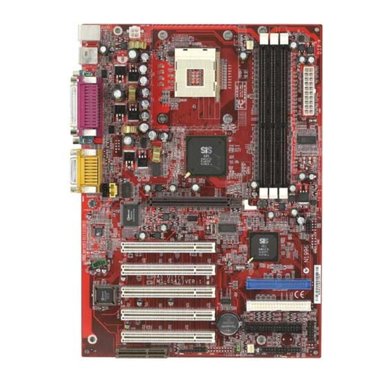
Page 11: Mainboard Layout
PCI Slot 1 JMD1 PCI Slot 2 IDE 1 PCI Slot 3 IDE 2 BIOS PCI Slot 4 JFP1 FDD 1 (optional) BATT PCI Slot 5 JFP2 SYSFA JLED1 (optional) JMDM1 JP20 JBAT1 JIR2 645 Ultra (MS-6547 v1.X) ATX Mainboard... -
Page 12: Quick Components Guide
Getting Started Quick Components Guide Component Function Reference JWR1/JPW1 ATX power connectors See p. 2-7 JKBMS1 Mouse/keyboard connector See p. 2-8 USB Connectors Connecting to USB devices See p. 2-9 COM A & COM B Serial port connector See p. 2-10 L P T 1 Parallel port connector See p. -
Page 13: Msi Special Features
Chapter 1 MSI Special Features T.O.P Tech™ The T.O.P Tech is an extended sensing device that can 100% accu- rately detect the CPU’s temperature. You can find out the temperature on BIOS setup menu. The PC Alert also provides the information. -
Page 14: Pc Alert™ Iii
Getting Started PC Alert™ III The PC Alert III is a utility you can find in the CD-ROM disk. The utility is just like your PC doctor that can de- tect the following PC hardware status during real time operation: * monitor CPU &... -
Page 15: Fuzzy Logic™ Iii
Chapter 1 Fuzzy Logic™ III The Fuzzy Logic™ III utility allows users to overclock the CPU FSB (Front Side Bus) frequency in the Windows environment. Select the CPU fre- quency you prefer and click Go to apply the frequency or click Save allowing the system to run at the specified frequency each time when the system is powered on. -
Page 16: Live Bios™/Live Driver
After installation, the “MSI Live Update Series” icon (as the right view) will appear on the screen. Double click the “MSI Live Update Series” icon, and the following screen will appear. Four buttons are placed on the left column of the screen. Click the desired button to start the update process. -
Page 17: D-Bracket
Chapter 1 D-Bracket™ D-Bracket™ is an USB bracket integrating four Diagnostic LEDs, which use graphic signal display to help users understand their system. The LEDs provide up to 16 combinations of signals to debug the system. The 4 LEDs can debug all problems that fail the system, such as VGA, RAM or other failures. - Page 18 Getting Started D-Bracket Description Processor Initialization - This will show information regarding the processor (like brand name, system bus, etc…) Testing RTC (Real Time Clock) Initializing Video Interface - This will start detecting CPU clock, checking type of video onboard. Then, detect and initialize the video adapter. BIOS Sign On - This will start showing information about logo, processor brand name, etc….
-
Page 19: Chapter 2. Hardware Setup
Hardware Setup Chapter 2. Hardware Setup Hardware Setup This chapter provides you with the information about hardware setup procedures. While doing the installation, be careful in holding the components and follow the installation procedures. For some components, if you install in the wrong orientation, the components will not work properly. -
Page 20: Central Processing Unit: Cpu
Chapter 2 Central Processing Unit: CPU ® ® The mainboard supports Intel Pentium 4 processor in the 478 pin package. The mainboard uses a CPU socket called PGA478 for easy CPU installation. When you are installing the CPU, make sure the CPU has a heat sink and a cooling fan attached on the top to prevent overheating. -
Page 21: Installing The Cpu Fan
Hardware Setup Installing the CPU Fan As processor technology pushes to faster speeds and higher performance, thermal managment becomes increasingly important. To dissi- pate heat, you need to attach the CPU cooling fan and heatsink on top of the CPU. Follow the instructions below to install the Heatsink/Fan: Locate the CPU and its retention Position the heatsink onto the reten- mechanism on the motherboard. -
Page 22: Cpu Core Speed Derivation Procedure
Chapter 2 Connect the fan power cable from the mounted fan to the 3-pin fan power connector on the board. fan power cable CPU Core Speed Derivation Procedure CPU Clock 100MHz Core/Bus ratio then CPU core speed Host Clock x Core/Bus ratio 100MHz x 14 1.4GHz Overclocking... -
Page 23: Memory
Hardware Setup Memory The mainboard provides 3 slots for 184-pin, 2.5V DDR DIMM with 6 memory banks. You can install PC1600/PC2100 DDR SDRAM modules on the DDR DIMM slots (DDR 1~3). To operate properly, at least one DIMM module must be installed. DDR DIMM Slots (DDR 1~3) Introduction to DDR SDRAM... -
Page 24: Ddr Module Combination
Chapter 2 DDR Module Combination You can install either single sided or double sided 184-pin DDR DIMM modules into DDR DIMM slots to meet your needs. Different from the SDR DIMM, the DDR DIMM has only one notch on the center of module. The number of pins on either side of the breaks are different. -
Page 25: Power Supply
Hardware Setup Power Supply The mainboard supports ATX power supply for the power system. Be- fore inserting the power supply connector, always make sure that all compo- nents are installed properly to ensure that no damage will be caused. ATX 20-Pin Power Connector: JWR1 This connector allows you to connect to an ATX power supply. -
Page 26: Back Panel
Chapter 2 Back Panel The Back Panel provides the following connectors: Parallel Midi/Joystick Mouse Keyboard USB COM A COM B L-out L-in MIC Mouse Connector: JKBMS1 ® The mainboard provides a standard PS/2 mouse mini DIN connector for ® ® attaching a PS/2 mouse. -
Page 27: Keyboard Connector: Jkbms1
Hardware Setup Keyboard Connector: JKBMS1 ® The mainboard provides a standard PS/2 keyboard mini DIN connector ® ® for attaching a PS/2 keyboard. You can plug a PS/2 keyboard directly into this connector. Pin Definition SIGNAL DESCRIPTION Keyboard DATA Keyboard DATA No connection Ground Keyboard Clock... -
Page 28: Serial Port Connector: Com A & Com B
Chapter 2 Serial Port Connector: COM A & COM B The mainboard offers two 9-pin male DIN connectors for serial port COM A and COM B. The ports are 16550A high speed communication ports that send/receive 16 bytes FIFOs. You can attach a serial mouse or other serial devices directly to them. -
Page 29: Parallel Port Connector: Lpt1
Hardware Setup Parallel Port Connector: LPT1 The mainboard provides a 25-pin female centronic connector for LPT. A parallel port is a standard printer port that supports Enhanced Parallel Port (EPP) and Extended Capabilities Parallel Port (ECP) mode. Pin Definition SIGNAL DESCRIPTION STROBE Strobe... -
Page 30: Connectors
Chapter 2 Connectors The mainboard provides connectors to connect to FDD, IDE HDD, case, modem, LAN, USB Ports, IR module and CPU/System FAN. Floppy Disk Drive Connector: FDD1 The mainboard provides a standard floppy disk drive connector that supports 360K, 720K, 1.2M, 1.44M and 2.88M floppy disk types. FDD 1 2-12... -
Page 31: Hard Disk Connectors: Ide1 & Ide2
Hardware Setup Hard Disk Connectors: IDE1 & IDE2 The mainboard has a 32-bit Enhanced PCI IDE and Ultra DMA 33/66/100 controller that provides PIO mode 0~4, Bus Master, and Ultra DMA/33/66/100 function. You can connect up to four hard disk drives, CD-ROM, 120MB Floppy (reserved for future BIOS) and other devices. -
Page 32: Cd-In Connector: Jcd1
Chapter 2 CD-In Connector: JCD1 The connector is for CD-ROM audio connector. Aux Line-In Connector: JAUX1 The connector is for DVD add-on card with Line-in connector. Modem-In Connector: JMD1 The connector is for modem with internal audio connector. JAUX1 JCD1 JMD1 Phone_In Mono_Out... -
Page 33: Fan Power Connectors: Cpufa/Sysfa
Hardware Setup Fan Power Connectors: CPUFA/SYSFA The CPUFA (processor fan) and SYSFA (system fan) support system cooling fan with +12V. It supports three-pin head connector. When connect- ing the wire to the connectors, always take note that the red wire is the positive and should be connected to the +12V, the black wire is Ground and should be connected to GND. -
Page 34: Wake On Ring Connector: Jmdm1
Chapter 2 Wake On Ring Connector: JMDM1 This connector allows you to connect to a modem card with Wake On Ring function. The connector will power up the system when a signal is re- ceived through the modem card. MDM_WAKEUP 5VSB JMDM1 IrDA Infrared Module Header: JIR2... -
Page 35: Front Panel Connector: Jfp1 Or Jfp2
Hardware Setup Front Panel Connector: JFP1 or JFP2 The mainboard provides one front panel connector for electrical connec- tion to the front panel switches and LEDs. Users can choose either the JFP1 or the JFP2 depending on their needs.The difference between JFP1 & JFP2 is that ®... -
Page 36: Front Panel Audio Connector: Jp20
Chapter 2 Front Panel Audio Connector: JP20 The JP20 front panel audio connector allows you to connect to the front panel audio and is compliant with Intel Front Panel I/O Connectivity Design Guide. JP20 Pin Definition SIGNAL DESCRIPTION AUD_MIC Front panel microphone input signal AUD_GND Ground used by analog audio circuits AUD_MIC_BIAS... -
Page 37: Front Usb Connector: Jusb1 Or Jusb3
USB devices. Users can choose either the JUSB1 or the ® JUSB3 depending on their needs. The JUSB3 is compliant with Intel Front Panel I/O Connectivity Design Guide. JUSB1 (MSI spec) JUSB3 (Intel spec) JUSB1 Pin Definition JUSB3 Pin Definition Description... -
Page 38: D-Bracket™ Connector: Jled1
Chapter 2 D-Bracket™ Connector: JLED1 The mainboard comes with a JLED1 connector for you to connect to D- Bracket™. D-Bracket™ is a USB Bracket integrating four LEDs and allows users to identify system problem through 16 various combinations of LED signals. -
Page 39: Clear Cmos Jumper: Jbat1
Hardware Setup Jumpers The motherboard provides one jumper for you to set the computer’s function. This section will explain how to change your motherboard’s function through the use of the jumper. Clear CMOS Jumper: JBAT1 There is a CMOS RAM on board that has a power supply from external battery to keep the data of system configuration. -
Page 40: Slots
Chapter 2 Slots The motherboard provides five 32-bit Master PCI bus slots, one AGP slot and one CNR slot. AGP Slot PCI Slots CNR Slot AGP (Accelerated Graphics Port) Slot The AGP slot allows you to insert the AGP graphics card. AGP is an interface specification designed for the throughput demands of 3D graphics. -
Page 41: Pci Interrupt Request Routing
Hardware Setup PCI Interrupt Request Routing The IRQ, abbreviation of interrupt request line and pronounced I-R-Q, are hardware lines over which devices can send interrupt signals to the microprocessor. The PCI IRQ pins are typically connected to the PCI bus INT A# ~ INT D# pins as follows: Order 1 Order 2... -
Page 42: Chapter 3. Bios Setup
BIOS Setup Chapter 3. BIOS Setup BIOS Setup This chapter provides information on the BIOS Setup program and allows you to configure the system for optimum use. You may need to run the Setup program when: An error message appears on the screen during the system booting up, and requests you to run SETUP. -
Page 43: Entering Setup
Chapter 3 Entering Setup Power on the computer and the system will start POST (Power On Self Test) process. When the message below appears on the screen, press <DEL> key to enter Setup. DEL:Setup F11:Boot Menu F12:Network boot TAB:Logo If the message disappears before you respond and you still wish to enter Setup, restart the system by turning it OFF and On or pressing the RESET button. -
Page 44: Control Keys
BIOS Setup Control Keys <↑> Move to the previous item Move to the next item <↓> Move to the item in the left hand <←> <→> Move to the item in the right hand <Enter> Select the item <Esc> Jumps to the Exit menu or returns to the main menu from a submenu <+/PU>... -
Page 45: The Main Menu
Chapter 3 The Main Menu Once you enter AMIBIOS EASY SETUP UTILITY, the Main Menu will appear on the screen. The Main Menu displays twelve configurable functions and two exit choices. Use arrow keys to move among the items and press <Enter> to enter the sub-menu. - Page 46 BIOS Setup Integrated Peripherals Use this menu to specify your settings for integrated peripherals. PC Health Status This entry shows your PC health status. Frequency/Voltage Control Use this menu to specify your settings for frequency/voltage control. Set Supervisor Password Use this menu to set Supervisor Password. Set User Password Use this menu to set User Password.
-
Page 47: Standard Cmos Features
Chapter 3 Standard CMOS Features The items inside STANDARD CMOS SETUP menu are divided into 9 catego- ries. Each category includes none, one or more setup items. Use the arrow keys to highlight the item you want to modify and use the <PgUp> or <PgDn> keys to switch to the value you prefer. - Page 48 BIOS Setup Primary/Secondary IDE Master/Slave Press PgUp/<+> or PgDn/<-> to select the hard disk drive type. The specifica- tion of hard disk drive will show up on the right hand according to your selection. TYPE Type of the device. Number of cylinders. Number of heads.
-
Page 49: Advanced Bios Features
Chapter 3 Advanced BIOS Features Quick Boot Setting the item to Enabled allows the system to boot within 5 seconds since it will skip some check items. Available options: Enabled and Disabled. Full Screen Logo Show This item enables you to show the company logo on the bootup screen. Set- tings are: Silent Shows the POST messages at boot. - Page 50 BIOS Setup as LS-120 or ZIP drive, that functions as a floppy drive. ARMD-HDD The system will boot from ARMD device, such as MO or ZIP drive, that functions as hard disk drive. CDROM The system will boot from the CD-ROM. SCSI The system will boot from the SCSI.
- Page 51 Chapter 3 Floppy Drive Swap Setting to Enabled will swap floppy drives A: and B:. Floppy Drive Seek This setting causes the BIOS to search for floppy disk drives at boot time. When enabled, the BIOS will activate the floppy disk drives during the boot process: the drive activity light will come on and the head will move back and forth once.
-
Page 52: Advanced Chipset Features
BIOS Setup Advanced Chipset Features Note: Change these settings only if you are familiar with the chipset. DRAM CAS# Latency The field controls the CAS latency, which determines the timing delay before SDRAM starts a read command after receiving it. Setting options: By SPD, 2. 5T, 2T. - Page 53 Chapter 3 Graphic Win Size The field selects the size of the Accelerated Graphics Port (AGP) aperture. Aperture is a portion of the PCI memory address range dedicated for graphics memory address space. Host cycles that hit the aperture range are forwarded to the AGP without any translation.
-
Page 54: Power Management Features
BIOS Setup Power Management Features IPCA Function This item is to activate the ACPI (Advanced Configuration and Power Man- agement Interface) function. If your operating system is ACPI-aware, such as Windows 98SE/2000/ME, select Yes. Available options: Yes and No. Sleep State This item specifies the power saving modes for ACPI function. - Page 55 Chapter 3 device to enhance Max Saving mode and stop CPU internal clock. Settings are Disabled and Enabled. Init VGA BIOS From S3 This setting allows the system to initialize the VGA BIOS from S3 (Suspend to RAM) sleep state. Setting options: Enabled and Disabled. Power/Sleep LED This item configures how the system uses power LED on the case to indicate the sleep state.
- Page 56 BIOS Setup Set Wake Up Events Press <Enter> to enter the sub-menu and the following screen appears: Wake Up On Ring/PME# /Codec, Resume By USB Device/PS2 Mouse/ Keyboard These fields specify whether the system will be awakened from power saving modes when activity or input signal of the specified hardware peripheral or component is detected.
-
Page 57: Pnp/Pci Configurations
Chapter 3 PNP/PCI Configurations This section describes configuring the PCI bus system and PnP (Plug & Play) feature. PCI, or Personal Computer Interconnect, is a system which allows I/O devices to operate at speeds nearing the speed the CPU itself uses when communicating with its special components. - Page 58 BIOS Setup the VGA Palette Snoop bit (0 is disabled). For example, if there are two VGA devices in the computer (one PCI and one ISA) and the: VGA Palette Snoop Bit Setting Action Disabled Data read or written by the CPU is only directed to the PCI VGA device’s palette registers.
- Page 59 Chapter 3 IRQ 3/4/5/7/9/10/11/14/15 These items specify the bus where the specified IRQ line is used. The settings determine if AMIBIOS should remove an IRQ from the pool of available IRQs passed to devices that are configurable by the system BIOS.
-
Page 60: Integrated Peripherals
BIOS Setup Integrated Peripherals Set Super I/O Press <Enter> to enter the sub-menu and the following screen appears: Floppy Controller This is used to enable or disable the onboard Floppy controller. 3-19... - Page 61 Chapter 3 Option Description Auto BIOS will automatically determine whether to enable the onboard Floppy controller or not. Enabled Enables the onboard Floppy controller. Disabled Disables the onboard Floppy controller. Serial Port A/B These items specify the base I/O port addresses of the onboard Serial Port 1 (COM A)/Serial Port 2 (COM B).
- Page 62 BIOS Setup Parallel Port DMA This feature needs to be configured only when Parallel Port Mode is set to the ECP mode. When Parallel Port is set to Auto, the field will show Auto indicating that BIOS automatically determines the DMA channel for the parallel port.
-
Page 63: Pc Health Status
Chapter 3 PC Health Status This section shows the status of your CPU, fan, warning for overall system status. CPU/System Fan Speed, CPU/System Temperature, Vcore, +3.3V, +5.0V, +12.0V, -12.0V, -5.0V, Battery Voltage These items display the current status of all of the monitored hardware de- vices/components such as CPU voltages, temperatures and all fans’... -
Page 64: Frequency/Voltage Control
BIOS Setup Frequency/Voltage Control Use this menu to specify your settings for frequency/voltage control. CPU FSB Clock (Mhz) This setting allows you to select the CPU Front Side Bus clock frequency. Setting options: 100MHz~200MHz at 1MHz increment. CPU:DRAM Clock Ratio This setting controls the ratio of CPU FSB Clock &... - Page 65 Chapter 3 Spread Spectrum When the motherboard clock generator pulses, the extreme values (spikes) of the pulses creates EMI (Electromagnetic Interference). The Spread Spectrum function reduces the EMI generated by modulating the pulses so that the spikes of the pulses are reduced to flatter curves. If you do not have any EMI problem, leave the setting at Disabled for optimal system stability and performance.
-
Page 66: Supervisor/User Password
BIOS Setup Supervisor/User Password When you select this function, a message as below will appear on the screen: Type the password, up to six characters in length, and press <Enter>. The password typed now will replace any previously set password from CMOS memory. -
Page 67: Load High Performance/Bios Setup Defaults
Chapter 3 Load High Performance/BIOS Setup Defaults The two options on the main menu allow users to restore all of the BIOS settings to High Performance defaults or BIOS Setup defaults. The High Per- formance Defaults are the default values set by the mainboard manufacturer for the best system performance but probably will cause a stability issue. -
Page 68: Glossary
Glossary Glossary Glossary ACPI (Advanced Configuration & Power Interface) This power management specification enables the OS (operating system) to control the amount of power given to each device attached to the computer. Windows 98/98SE, Windows 2000 and Windows ME can fully support ACPI to allow users managing the system power flexibly. AGP (Accelerated Graphics Port) A new, high-speed graphics interface that based on PCI construction and designed especially for the throughput demands of 3-D graphics. - Page 69 Glossary a PC chipset provides the electronic interfaces between all subsystems. CMOS (complementary metal-oxide semiconductor) CMOS is a widely used type of semiconductor, which features high speed and low power consumption. PCs usually contain a small amount of battery-powered CMOS memory to retain the date, time, and system setup parameters.
- Page 70 Glossary ECC Memory (error correcting code memory) A type of memory that contains special circuitry for testing the accuracy of data and correcting the errors on the fly. IDE (Integrated Drive Electronics) A type of disk-drive interface widely used to connect hard disks, CD-ROMs and tape drives to a PC, in which the controller electronics is integrated into the drive itself, eliminating the need for a separate adapter card.
- Page 71 Glossary PnP (Plug and Play) A set of specifications that allows a PC to configure itself automatically to work with peripherals. The user can "plug" in a peripheral device and "play" it without configuring the system manually. To implement this useful feature, both the BIOS that supports PnP and a PnP expansion card are required.
Need help?
Do you have a question about the 645 Ultra and is the answer not in the manual?
Questions and answers