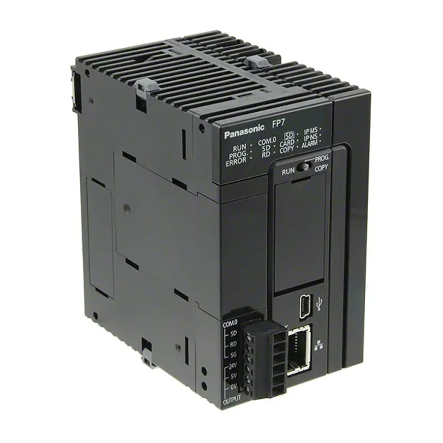
Panasonic FP7 User Manual
Digital i/o units
Hide thumbs
Also See for FP7:
- Command reference manual (1222 pages) ,
- User manual (275 pages) ,
- Additional functions manual (45 pages)

Related Manuals for Panasonic FP7


Summary of Contents for Panasonic FP7
- Page 1 PROGRAMMABLE CONTROLLERS User's Manual FP7 Digital I/O Units ACGM0704V1.1EN 2021.05 industry.panasonic.eu...
- Page 2 This manual and everything described in it are copyrighted. You may not copy this manual, in whole or part, without written consent of Panasonic Electric Works Europe AG (PEWEU). PEWEU pursues a policy of continuous improvement of the design and performance of its products.
- Page 3 Indicates a hazardous situation which, if not avoided, could result in serious or moderate injury. CAUTION Indicates a hazardous situation which, if not avoided, could result in minor or moderate injury. NOTICE Indicates a property damage message. FP7 Digital I/O Units User's Manual...
- Page 4 memory area tables programming examples For documentation on other units used with the FP7, please refer to the hardware manual for that unit. All manuals can be downloaded from the Panasonic Web site (industry.panasonic.eu). FP7 Digital I/O Units User's Manual...
- Page 5 An insulated power supply with an internal protective circuit should be used (FP power supply). The power supply for the CPU is a non-insulated circuit, so if an incorrect voltage is directly applied, the internal circuit may be damaged or destroyed. FP7 Digital I/O Units User's Manual...
- Page 6 Also, if a password is forcibly bypassed, the program is deleted. Therefore, please note the password in a safe location. FP7 Digital I/O Units User's Manual...
-
Page 7: Table Of Contents
3.3.2 Protective circuit for capacitive loads ............51 3.3.3 Overload protection ................. 51 3.3.4 Grounding of AFP7Y16R ................52 Wiring the terminal block ................... 53 Wiring the MIL connector ................... 54 3.5.1 Connectors for wire-pressed terminal cables ..........54 FP7 Digital I/O Units User's Manual... - Page 8 Table of contents 3.5.2 Flat cable connectors ................57 FP7 Digital I/O Units User's Manual...
-
Page 9: Overview
Load current: 1A/output, AFP7Y16P source (PNP) block 5A/common; 16 outputs/common Load current: 0.3A/output, AFP7Y32P connector 3.2A/common; 32 outputs/common Load current: 0.3A (8 AFP7Y64P connector outputs, Y0–Y7) and 0.1A (56 outputs, Y8–Y3F); 3.2A/common; 32 outputs/common FP7 Digital I/O Units User's Manual... -
Page 10: Parts And Functions
Y0–Y7) and 0.1A (24 outputs: Y8–Y1F); 3.2A/common and 32 outputs/common 1.2 Parts and functions Terminal block type, 16 inputs MIL connector type, 32 inputs MIL connector type, 64 inputs Q Input status LEDs/Output status LEDs FP7 Digital I/O Units User's Manual... - Page 11 U Input/output LED selector Switches between the first 32 LEDs and the second 32 LEDs of the display for units with 64 I/Os. I Expansion hook Used to fix expansion units. FP7 Digital I/O Units User's Manual...
-
Page 12: Specifications
(based on in-house measurements) Operation Free from corrosive gases and excessive dust conditions Conformity to CE EMC: EN 61131-2, LVD: EN 61131-2 Directives Overvoltage category Pollution degree Based on JIS B 3502 and IEC 61131-2 FP7 Digital I/O Units User's Manual... -
Page 13: Current Consumption
FALSE TRUE 0.1ms (input time constant configurable) TRUE FALSE 0.2ms (input time constant configurable) Input points per common Input status LEDs 16 (lit in ON state) Connection Terminal block (Terminal screw M3) Weight 125g FP7 Digital I/O Units User's Manual... -
Page 14: Inputs (Afp7X32D2)
FALSE TRUE 0.2ms (input time constant configurable) TRUE FALSE 0.2ms (input time constant configurable) Input points per common Input status LEDs 32 (lit in ON state) Connection 40-pin MIL connector Weight 95g FP7 Digital I/O Units User's Manual... - Page 15 Specifications Internal circuit diagram Q Internal circuit Terminal layout The COM terminals of the input circuits are connected internally. FP7 Digital I/O Units User's Manual...
-
Page 16: Inputs (Afp7X64D2)
Keep the number of inputs per common which are simultaneously TRUE within the following range as determined by the ambient temperature. x Ambient temperature y Number of inputs per common that are TRUE simultaneously Q At 26.4V DC W At 24V DC FP7 Digital I/O Units User's Manual... - Page 17 Specifications Internal circuit diagram Q Internal circuit Terminal layout The COM terminals of each connector are connected internally. FP7 Digital I/O Units User's Manual...
-
Page 18: Output Unit Specifications
16-point LED indicator (lit in ON state) Connection Terminal block (M3 terminal screws) Weight 180g Internal circuit diagram Q Internal circuit 2 Load In order to avoid the effects of noise, be sure to ground the function earth terminal. FP7 Digital I/O Units User's Manual... - Page 19 Specifications Restriction on power supply voltage Refer to the following figure and reduce the supply voltage according to the ambient temperature. x Ambient temperature y Power supply voltage Terminal layout FP7 Digital I/O Units User's Manual...
-
Page 20: Sink (Npn) Outputs (Afp7Y16T)
Zener diode Short circuit protection – Outputs per common Operation indicator 16-point LED indicator (lit in ON state) Connection Terminal block (M3 terminal screws) Weight 125g Internal circuit diagram Q Internal circuit 2 Load FP7 Digital I/O Units User's Manual... -
Page 21: Source (Pnp) Outputs (Afp7Y16P)
4.75–26.4V DC Current 70mA (at 24V DC) Surge absorber Zener diode Short circuit protection – Outputs per common Operation indicator 16-point LED indicator (lit in ON state) Connection Terminal block (M3 terminal screws) Weight 125g FP7 Digital I/O Units User's Manual... - Page 22 Specifications Internal circuit diagram Q Internal circuit 2 Load Terminal layout FP7 Digital I/O Units User's Manual...
-
Page 23: Sink (Npn) Outputs (Afp7Y32T)
Surge absorber Zener diode Short circuit protection – Outputs per common Operation indicator 32-point LED indicator (lit in ON state) Connection 40-pin MIL connector Weight 95g Internal circuit diagram Q Internal circuit 2 Load FP7 Digital I/O Units User's Manual... - Page 24 Refer to the following figure and reduce the load current according to the external power supply voltage. x External power supply voltage y Max. load current Terminal layout Although the positive and negative terminals are connected internally, connect these terminals externally as well. FP7 Digital I/O Units User's Manual...
-
Page 25: Source (Pnp) Outputs (Afp7Y32P)
Surge absorber Zener diode Short circuit protection – Outputs per common Operation indicator 32-point LED indicator (lit in ON state) Connection 40-pin MIL connector Weight 95g Internal circuit diagram Q Internal circuit 2 Load FP7 Digital I/O Units User's Manual... - Page 26 Refer to the following figure and reduce the load current according to the external power supply voltage. x External power supply voltage y Max. load current Terminal layout Although the positive and negative terminals are connected internally, connect these terminals externally as well. FP7 Digital I/O Units User's Manual...
-
Page 27: Sink (Npn) Outputs (Afp7Y64T)
Surge absorber Zener diode Short circuit protection – Outputs per common Operation indicator 32-point LED indicator (lit in ON state) Connection 40-pin MIL connector x2 Weight 115g Internal circuit diagram Q Internal circuit 2 Load FP7 Digital I/O Units User's Manual... - Page 28 Refer to the following figure and reduce the load current according to the external power supply voltage. Y0–Y7, 0.3A/output: x External power supply voltage y Max. load current Any other output, 0.1A/output: x External power supply voltage y Max. load current FP7 Digital I/O Units User's Manual...
-
Page 29: Source (Pnp) Outputs (Afp7Y64P)
FALSE TRUE 0.1ms (load current: 2mA) TRUE FALSE 0.5ms (load current: 2mA) External power Voltage 4.75–26.4V DC supply Current 90mA/common (at 24V DC) Surge absorber Zener diode Short circuit protection – Outputs per common FP7 Digital I/O Units User's Manual... - Page 30 Q At 24V DC W At 26.4V DC Internal circuit diagram Q Internal circuit 2 Load Restrictions on load current Refer to the following figure and reduce the load current according to the external power supply voltage. FP7 Digital I/O Units User's Manual...
- Page 31 Specifications Y0–Y7, 0.3A/output: x External power supply voltage y Max. load current Any other output, 0.1A/output: x External power supply voltage y Max. load current FP7 Digital I/O Units User's Manual...
- Page 32 Specifications Terminal layout Although the positive and negative terminals are connected internally, connect these terminals externally as well. FP7 Digital I/O Units User's Manual...
-
Page 33: Mixed I/O Unit Specifications
4.75–26.4V DC supply Current 70mA/common (at 24V DC) Surge absorber Zener diode Short circuit protection – Outputs per common Operation indicator 32-point LED indicator (lit in ON state) Connection 40-pin MIL connector x2 Weight 115g FP7 Digital I/O Units User's Manual... - Page 34 TRUE within the following range as determined by the ambient temperature. x Ambient temperature y Number of inputs/outputs per common that are TRUE simultaneously Q At 24V DC W At 26.4V DC Internal circuit diagram Input: Q Internal circuit FP7 Digital I/O Units User's Manual...
- Page 35 2 Load Restrictions on load current Refer to the following figure and reduce the load current according to the external power supply voltage. Y0–Y7, 0.3A/output: x External power supply voltage y Max. load current FP7 Digital I/O Units User's Manual...
- Page 36 Specifications Any other output, 0.1A/output: x External power supply voltage y Max. load current Terminal layout Input: The COM terminals of the input circuits are connected internally. FP7 Digital I/O Units User's Manual...
- Page 37 Specifications Output: Although the positive and negative terminals are connected internally, connect these terminals externally as well. FP7 Digital I/O Units User's Manual...
-
Page 38: Inputs/32 Source (Pnp) Outputs (Afp7Xy64D2P)
4.75–26.4V DC supply Current 90mA/common (at 24V DC) Surge absorber Zener diode Short circuit protection – Outputs per common Operation indicator 32-point LED indicator (lit in ON state) Connection 40-pin MIL connector x2 Weight 115g FP7 Digital I/O Units User's Manual... - Page 39 TRUE within the following range as determined by the ambient temperature. x Ambient temperature y Number of inputs/outputs per common that are TRUE simultaneously Q At 26.4V DC W At 24V DC Internal circuit diagram Input: Q Internal circuit FP7 Digital I/O Units User's Manual...
- Page 40 2 Load Restrictions on load current Refer to the following figure and reduce the load current according to the external power supply voltage. Y0–Y7, 0.3A/output: x External power supply voltage y Max. load current FP7 Digital I/O Units User's Manual...
- Page 41 Specifications Any other output, 0.1A/output: x External power supply voltage y Max. load current Terminal layout Input: The COM terminals of the input circuits are connected internally. FP7 Digital I/O Units User's Manual...
- Page 42 Specifications Output: Although the positive and negative terminals are connected internally, connect these terminals externally as well. FP7 Digital I/O Units User's Manual...
-
Page 43: Input Time Constant Setting Function
The accuracy of each time constant is shown in the table below. Set value Time constant Min. Max. No setting – – 0.1ms 0.1ms 0.2ms 0.5ms 0.3ms 0.7ms 0.7ms 1.3ms 3.0ms 5.2ms 10ms 6.0ms 10.4ms 20ms 12.1ms 20.7ms 70ms 48.6ms 82.8ms FP7 Digital I/O Units User's Manual... -
Page 44: Wiring
For connecting input devices see the diagrams and recommendations given below. 3.2.1 Photoelectric and proximity sensors Relay output type NPN input: Sensor Q Internal circuit W Relay E Power supply for sensor R Power supply for input T Input terminal FP7 Digital I/O Units User's Manual... - Page 45 W Relay E Power supply for sensor R Power supply for input T Input terminal Open collector output type NPN output: Sensor Q Internal circuit W Output E Power supply for input R Input terminal FP7 Digital I/O Units User's Manual...
- Page 46 PNP output: Sensor Q Internal circuit W Output E Power supply for input R Input terminal Voltage output (universal output) type Sensor Q Internal circuit W Output E Power supply for input R Input terminal FP7 Digital I/O Units User's Manual...
-
Page 47: Input Wiring Precautions
LED-equipped Reed switch, make sure that the voltage applied to the PLC input terminal is greater than the ON voltage. In particular, take care when connecting a number of switches in series. LED-equipped Reed switch Q LED W Contact E ON voltage R Input terminal FP7 Digital I/O Units User's Manual... - Page 48 2.5V. The input impedance is 3.6k. Therefore: The wattage W of the resistor is: V = Power supply voltage In the actual selection, use a value that is 3 to 5 times the value of W. FP7 Digital I/O Units User's Manual...
- Page 49 The input impedance is 3.6k. The resistance R of the bleeder resistor is: The wattage W of the resistor is: V = Power supply voltage In the actual selection, use a value that is 3 to 5 times the value of W. FP7 Digital I/O Units User's Manual...
-
Page 50: Output Wiring
Using an AC inductive load (relay output type) Q Output terminal W Load E Surge absorber, e.g. resistance R: 50, capacitance C: 0.47F Output terminal Load Varistor Using a DC inductive load Output terminal Load Diode FP7 Digital I/O Units User's Manual... -
Page 51: Protective Circuit For Capacitive Loads
There are times that the elements for the output units cannot be protected even if external fuses are connected. FP7 Digital I/O Units User's Manual... -
Page 52: Grounding Of Afp7Y16R
Always use an exclusive ground for PLCs and other devices. If two devices share a single ground point, it may produce an adverse effect. Q PLC W Other device (inverter etc.) FP7 Digital I/O Units User's Manual... -
Page 53: Wiring The Terminal Block
To reattach the terminal block, insert it all the way to its original N o t e position and press the lock button on the bottom of the unit. Then confirm that the terminal block is securely attached and cannot be removed. FP7 Digital I/O Units User's Manual... -
Page 54: Wiring The Mil Connector
Units with 32 I/Os are provided with one set, units with 64 I/Os and N o t e mixed I/O units are provided with two sets each. If you need more connectors, purchase AFP2801 (2 sets/pack). Pressure connection tool (AXY52000FP) FP7 Digital I/O Units User's Manual... - Page 55 1. Bend the contact back from the carrier and set it in the pressure connection tool 2. Insert wire without removing its insulation until it stops 3. Lightly grip tool 4. Insert press-fitted wire into connector housing FP7 Digital I/O Units User's Manual...
- Page 56 Q Press the housing against the pressure connection tool so that the contact puller pin comes in contact with this section. FP7 Digital I/O Units User's Manual...
- Page 57 Connection diagram for units with 64 inputs or outputs and for mixed I/O units Q Cable no. 1 Connector 1 (CN1) Cable no. Input no. Output no. Cable no. Input no. Output no. FP7 Digital I/O Units User's Manual...
- Page 58 Connector 2 (CN2) Cable no. Input no. Output no. Cable no. Input no. Output no. Suitable wire (strand wire) Size Pitch Rated current AWG28 (7 wires/ 0.127) 1.27mm FP7 Digital I/O Units User's Manual...
- Page 59 Record of changes Manual no. Date Description of changes ACGM0704V1EN September 2014 First edition ACGM0704V1.1EN Updated company address and Web site May 2021...
Need help?
Do you have a question about the FP7 and is the answer not in the manual?
Questions and answers