Table of Contents
Advertisement
Quick Links
Advertisement
Table of Contents

Subscribe to Our Youtube Channel
Related Manuals for Lorex LNZ81P25 Series


Summary of Contents for Lorex LNZ81P25 Series
- Page 1 Instruction Manual LNZ81P25 Series...
- Page 3 Instruction Manual LNZ81P25 Series #LX400116; r. 4.0/60127/60127; en-US...
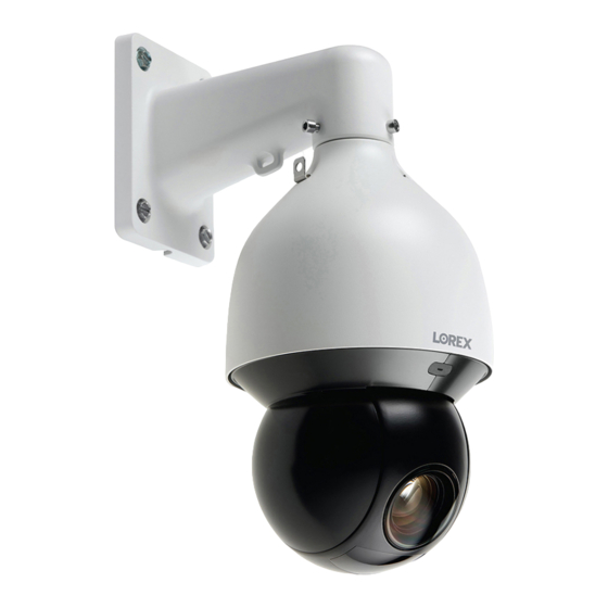
- Page 4 Thank you for purchasing this product. Lorex Technology Inc. is committed to providing our customers with a high quality, reliable security solution. This manual refers to the following models: LNZ81P25 For the latest online manual, downloads and product updates, and to learn about our complete line of accessory products, please visit our website at: lorex.com...
-
Page 5: Table Of Contents
Table of contents Safety Instructions ................1 Getting Started..................2 Connecting the Camera ................. 3 Option 1: Connecting the Camera to an NVR........3 Option 2: Connecting Cameras to the Local Area Network (LAN) ....3 Adding the PTZ Camera to an NVR:..........5 Installation .................. -
Page 7: Safety Instructions
Safety Instructions • Read this guide carefully and keep it for future reference. • Follow all instructions for safe use of the product and handle with care. • Use the camera within given temperature, humidity, and voltage levels noted in the 9 Techni- cal Specifications, page 26. -
Page 8: Getting Started
Getting Started The camera comes with the following components: PTZ Camera Wall Mount Power Adapter Mounting anchors, screws, flat ESD Gloves Safety Chain washers (x4) Waterproof Tape Waterproof Connector Allen Key Torx Key M6x14 Screws (x3) Rubber Ring NOTE Your accessories might appear different from the ones depicted in this guide. The following are user supplied tools (not included). -
Page 9: Connecting The Camera
• For the most up-to-date list of compatible NVRs, please visit lorex.com/compatibility. 3. Alarm: Connect the camera to an alarm system using alarm output (blue), alarm communi- cation (green), alarm ground (yellow and green), alarm input (red and/or brown). - Page 10 1. Connect an Ethernet cable of up to 300ft (91m) rated CAT5e or higher (not included) from the LAN port on an external PoE+ switch (sold separately on lorex.com) to your router. Con- nect the power cable to the PoE+ switch and to a power outlet or surge protector.
-
Page 11: Adding The Ptz Camera To An Nvr
Connecting the Camera Step 1 of 2 — Option B: Connecting the camera to your local network using a power adapter: 1. Connect the camera to the included power adapter using red for DV24V(+), black for GND (-), yellow & green for earth. 2. - Page 12 Connecting the Camera 3. Click Search Device. The system searches the network for compatible cameras. 4. Check the camera(s) you would like to add. 5. Click Add. The Status indicator turns green to show the camera is successfully connected. NOTE You can also add a camera to a specific channel by hovering the mouse over an empty channel in split-screen view and clicking .
-
Page 13: Installation
This camera includes all components required for wall mounting. For the most up-to-date software and complete instruction manuals: 1. Visit lorex.com. 2. Search for the model number of your product. 3. Click on your product in the search results. 4. Click on the Downloads tab. - Page 14 Installation 3. Use the included wall mount to mark holes for the mounting anchors (x4) and cables. NOTE Vertical distance between marked holes — 5.3"/135mm Horizontal distance between marked holes — 4"/102mm Cable hole diameter — 2”/50mm 4. Drill holes (drill bit size — 3/8”) to a depth of 2.8”/70mm in the mounting surface where marked.
- Page 15 Installation 6. Connect the safety chain between the camera and the wall mount. This allows the camera to hang from the wall mount while connecting the cables. CAUTION • You must connect the safety chain between the camera and the wall mount to protect the camera from falling while connecting the cables.
- Page 16 Installation 7. Push the connection cables into the wall mount 8. Push the camera into the wall mount with the flat surfaces aligned on the inside. This will al- low the M6x14 screws (x3) to align with the holes on the camera. 9.
- Page 17 Installation A: Camera Ethernet Connector B: O-ring C: Barrel D: Stopper E: End Cap 10.1. Fit the o-ring around the camera Ethernet connector. 10.2. Feed the Ethernet extension cable through the end cap and the barrel then connect the cable to the camera Ethernet connector. 10.3.
- Page 18 Installation 13. Use the included Torx Key, mounting screws (x4) and flat washers (x4) to firmly attach the wall mount to the mounting surface. NOTE Imagery for illustration purposes only. #LX400116; r. 4.0/60127/60127; en-US...
- Page 19 Installation WARNING Make sure to install the wall mount bracket in a location that can support the camera’s weight. If mounting the camera on a drywall surface, you must drill at least 2 of the mounting screws through a wooden stud to ensure a stable mount.
- Page 20 Installation 14. Remove the protective vinyl sheet covering the camera lens once installation is completed. #LX400116; r. 4.0/60127/60127; en-US...
-
Page 21: Controlling The Ptz Camera With The N883 Series Nvr
The following instructions are based on the N883 Series . See your ’s instruction manual for in- structions on controlling the PTZ camera with your system. For the latest list of compatible s, please visit lorex.com/compatibility. To connect the PTZ camera to the system: 1. -
Page 22: Advanced Ptz Controls
Controlling the PTZ camera with the N883 Series NVR 5.2 Advanced PTZ Controls Advanced PTZ controls can be used to save camera positions and cycle through various posi- tions, and automate camera actions. To open advanced PTZ controls: • Click the arrow in the PTZ control window to open advanced controls. Advanced PTZ controls overview: 1. -
Page 23: Tours
Controlling the PTZ camera with the N883 Series NVR To go to a preset location: • Under No., select the number of the preset you want to go to, then click 5.2.2 Tours Tours will cycle through a set of presets. To add tours: 1. -
Page 24: Auto Tracking
Auto Tracking Auto Tracking is an advanced function on the PTZ camera that allows it to cover a large area and to automatically detect, follow, and record moving objects, such as a person or vehicle. The auto tracking technology is composed of both AI detection and tracking. When an object triggers the smart motion plus rule, the PTZ camera will automatically use its pan/tilt rotation and zoom feature to lock in the moving object in the center of the screen and continue to follow it without missing any details. -
Page 25: Create A Preset For Auto Tracking
Auto Tracking 2. Click EVENTS. Click the Event Settings tab from the side panel, then the Smart Plan tab from the drop-down. 3. Under Camera, select your connected IP PTZ camera. 4. Select the Smart Motion Plus feature. NOTE When a smart feature icon is enabled, the icon appears blue. Click the blue smart feature icon again to dis- able it. - Page 26 Auto Tracking 2. Click EVENTS. Click the Event Settings tab from the side panel, then the Smart Motion tab from the drop-down. 3. Under Camera, select your connected PTZ camera. 4. Click Add to create a detection rule. Auto Tracking is enabled by default. 5.
- Page 27 Auto Tracking 6. Click the Draw icon and customize the active area for auto tracking: • Preset: Select the preset that you have created for your PTZ camera. If you have not yet created one, see 5.2.1 Presets, page 16 for full instructions, otherwise auto tracking will not work.
-
Page 28: Disable Auto Tracking
Auto Tracking 7. Click the Trigger icon to set the auto-tracking schedule and to adjust the tracking duration. 8. Click Setting next to Schedule to choose which days and times of the week to enable auto tracking. 9. To adjust how long the camera will automatically track a moving object, enter the Tracking Duration number (next to Auto Tracking). - Page 29 Auto Tracking 2. Click EVENTS. Click the Event Settings tab from the side panel, then the Smart Motion tab from the drop-down. 3. Under Camera, select your connected PTZ camera. 4. Click the Trigger icon 5. Uncheck Auto Tracking. 6. Click OK, then Apply to save changes. #LX400116;...
-
Page 30: Inserting The Microsd Card (Optional) And Resetting The Camera
Inserting the microSD Card (Optional) and Resetting the Camera The camera features a hard reset button that is used to reset all camera settings back to the de- fault values. This is useful in case you want to revert camera image settings back to the default values. -
Page 31: Troubleshooting
• If you are using a PoE switch, it must be PoE+ rated (PoE class 4). Standard PoE switches are not adequate to power the camera. PoE+ switches are available for purchase on lorex.com (model #: ACCLPS263B (16–channel model)). • Ensure the camera is connected to a router on the same network as the . -
Page 32: Technical Specifications
5.4-135mm F1.6- F4.0 / Zoom Module Optical Zoom 25× Digital Zoom Yes — Digital zoom is a function controlled by the connected NVR. For a list of compatible NVRs visit: lorex.com/compatibility. Pan/Tilt Range Pan: 0°–360° endless Tilt: —15°~90° Auto Flip Yes, 180°... -
Page 33: Dimensions
Technical Specifications 9.1 Dimensions 9.1.1 Camera & Wall Mount 9.1.2 Wall Mount #LX400116; r. 4.0/60127/60127; en-US... -
Page 34: Wall Mount Holes & Cable Hole
Technical Specifications 9.1.3 Wall Mount Holes & Cable Hole #LX400116; r. 4.0/60127/60127; en-US... - Page 36 Legal disclaimer As our product is subject to continuous improvement, Lorex Corporation & subsidiaries reserve the right to modify product design, specifications & prices without notice and without incurring any obligation.E&OE.
Need help?
Do you have a question about the LNZ81P25 Series and is the answer not in the manual?
Questions and answers