Table of Contents
Advertisement
Quick Links
Advertisement
Table of Contents
Troubleshooting

Related Manuals for Mindray VS 9


Summary of Contents for Mindray VS 9
- Page 1 VS 9/VS 9A/VS 9C VS 8/VS 8A/VS 8C Vital Signs Monitor Operator’s Manual...
- Page 3 © Copyright 2020-2021 Shenzhen Mindray Bio-Medical Electronics Co., Ltd. All rights reserved. Release time: 2021-04 Revision: 4.0...
- Page 4 Responsibility on the Manufacturer Party Contents of this manual are subject to changes without prior notice. All information contained in this manual is believed to be correct. Mindray shall not be liable for errors contained herein nor for incidental or consequential damages in connection with the furnishing, performance, or use of this manual.
- Page 5 PARTICULAR PURPOSE. Exemptions Mindray's obligation or liability under this warranty does not include any transportation or other charges or liability for direct, indirect or consequential damages or delay resulting from the improper use or application of the product or the use of parts or accessories not approved by Mindray or repairs by people other than Mindray authorized personnel.
- Page 6 As a health care provider, you may report the occurrence of certain events to SHENZHEN MINDRAY BIO-MEDICAL ELECTRONICS CO., LTD., and possibly to the competent authority of the Member state in which the user and / or patient is established.
- Page 7 Preface Manual Purpose The pulse oximeter is to be operated by, or under the supervision of, qualified personnel only. The manual, accessories, directions for use, all precautionary information, and specifications should be read before use. This manual contains the instructions necessary to operate the product safely and in accordance with its function and intended use.
- Page 8 This page intentionally left blank. 2 - 6...
-
Page 9: Table Of Contents
2.5 Contra-indications ............................2 - 2 2.6 Applied Parts ..............................2 - 2 2.7 Main Unit .................................2 - 2 2.7.1 Front View (VS 9 Series) ......................2 - 2 2.7.2 Front View (VS 8 Series) ......................2 - 3 2.7.3 Side View (VS 9 Series) .........................2 - 5 2.7.4 Side View (VS 8 Series) .........................2 - 6... - Page 10 3.8.3 Quick Keys ............................. 3 - 10 3.8.4 On-screen Symbols ........................3 - 10 3.9 Configuring Your Monitor ........................3 - 11 3.9.1 Setting Device Location ......................3 - 11 3.9.2 Setting the Workflow ........................ 3 - 12 3.9.3 Adjusting Screen Brightness ....................3 - 18 3.9.4 Adjusting the Volume ......................
- Page 11 6 Networked Monitoring ......................6 - 1 6.1 Network Introduction ..........................6 - 1 6.2 Network Safety Information ........................6 - 1 6.3 Connecting the Monitor to the CMS .....................6 - 2 6.4 Connecting the eGateway .........................6 - 2 6.5 MLDAP ................................6 - 2 6.6 Connecting the Wireless Network ......................6 - 3 7 Alarms ............................7 - 1 7.1 Alarm Introduction ............................7 - 1...
- Page 12 8.6.6 Displaying SIQ (for Masimo SpO ) ..................8 - 10 8.6.7 Changing Averaging Time (for Masimo SpO ) ..............8 - 10 8.6.8 Changing the Sensitivity (for Mindray SpO ) ..............8 - 11 8.6.9 Showing/Hiding PI ........................8 - 11 8.6.10 Monitoring SpO and NIBP Simultaneously ..............
- Page 13 10.5.5 Replacing the Battery ......................10 - 12 10.5.6 Troubleshooting ........................10 - 12 10.5.7 Cleaning the TemporalScanner™ Thermometer ............10 - 13 10.6 Monitoring Temp with HeTaida Thermometer ................10 - 13 10.6.1 Overview of HeTaida Thermometer ................10 - 13 10.6.2 Taking a Temperature with HeTaida Thermometer ..........10 - 14 10.7 Manually Inputting Temp ........................10 - 14 11 Measuring Noninvasive Blood Pressure (NIBP) ..............11 - 1 11.1 NIBP Introduction ............................
- Page 14 11.12.2 NIBP Accuracy Test ......................11 - 18 11.13 NIBP Troubleshooting ........................11 - 18 12 Monitoring CO ........................12 - 1 12.1 Overview ..............................12 - 1 12.2 Safety ................................12 - 1 12.3 Measurement Limitations ........................12 - 2 12.4 CO Display ...............................
- Page 15 15.1.4 EWS Scoring in Continuous Monitoring Mode ............. 15 - 4 15.1.5 EWS Alarm ..........................15 - 5 15.1.6 Changing EWS Settings ......................15 - 6 15.1.7 Viewing History Scores ......................15 - 7 15.2 Glasgow Coma Scale (GCS) ........................15 - 8 15.2.1 GCS Display ..........................
- Page 16 18.14.1 The Scanner Info. Tab ......................18 - 16 18.14.2 The JADAK Barcode Tab ....................18 - 17 18.14.3 The Identify Scanner Tab (for the non-Mindray Custom 2D Barcode Reader) ...18 - 18.14.4 The Field Tab (for the Mindray Custom 2D Barcode Reader) ......18 - 18 18.15 The Record Settings ...........................18 - 18...
- Page 17 19.3.2 Battery Symbols ........................19 - 2 19.3.3 Battery-related Alarms ......................19 - 3 19.4 Replacing the Battery (for VS 9 Series) .................... 19 - 3 19.5 Replacing the Battery (For VS 8 Series) ................... 19 - 4 19.6 Connecting an External Battery ......................19 - 5 19.7 Charging a Battery ..........................
- Page 18 A.3 Power Supply Specifications ........................A - 3 A.3.1 AC Power Supply Specifications .................... A - 3 A.3.2 Battery Specifications of VS 9 Series ..................A - 3 A.3.3 Battery Supply Specifications of VS 8 Series ..............A - 4 A.4 Physical Specifications ..........................
- Page 19 A.5.10 Blue Tooth Specification ......................A - 7 A.5.11 Bluetooth Performance Specifications ................A - 7 A.6 Measurement Specifications ........................A - 8 A.6.1 SpO Specifications ........................A - 8 A.6.2 PR ..............................A - 11 A.6.3 NIBP ..............................A - 12 A.6.4 Temp Specifications .........................A - 14 A.6.5 CO Specifications ........................A - 16...
- Page 20 D.2.9 Other System Technical Alarm Messages .................D - 10 E Abbreviations ..........................E - 1 F Declaration of Conformity ......................F - 1...
-
Page 21: Safety
Safety Safety Information WARNING • Indicates a potential hazard or unsafe practice that, if not avoided, could result in death or serious injury. CAUTION • Indicates a potential hazard or unsafe practice that, if not avoided, could result in minor personal injury or product/property damage. NOTE •... -
Page 22: Cautions
• The software equipment copyright is solely owned by Mindray. No organization or individual shall resort to modifying, copying, or exchanging it or to any other infringement on it in any form or by any means without due permission. -
Page 23: Notes
• Ensure that the equipment is supplied with continuous electric power during work. Sudden power failure may cause data loss. • Magnetic and electrical fields are capable of interfering with the proper performance of the equipment. For this reason make sure that all external devices operated in the vicinity of the equipment comply with the relevant EMC requirements. -
Page 24: Equipment Symbols
Equipment Symbols Some symbols may not appear on your equipment. Caution Serial number Refer to instruction manual/ Date of manufacture booklet Direct current Alternating current Battery indicator Input/output USB connector Equipotentiality DEFIBRILLATION-PROOF TYPE BF DEFIBRILLATION-PROOF TYPE APPLIED PART CF APPLIED PART Gas inlet Gas outlet Graphical record... - Page 25 TrueBP is Mindray's new non-invasive blood pressure measurement algorithm using linear inflation technology, which can measure the blood pressure quickly and comfortably during cuff inflation. TrueResp is Mindray's new respiration algorithm using pulse wave amplitude variation from SpO 1 - 5...
- Page 26 This page intentionally left blank. 1 - 6...
-
Page 27: Equipment Introduction
The monitors are to be used in healthcare facilities by clinical professionals or under their guidance. They should only be used by persons who have received adequate training in their use. VS 9/VS 9A/VS 9C/VS 8/VS 8A/VS 8C Vital Signs Monitors are not intended for helicopter transport, hospital ambulance, or home use. -
Page 28: Contra-Indications
The VS Series Monitors are not intended for helicopter transport, hospital ambulance, or home use. Contra-indications None. Applied Parts The applied parts of the monitor are: ■ sensor ■ Temp probe ■ NIBP cuff ■ sampling line/nasal sampling cannula Main Unit 2.7.1 Front View (VS 9 Series) Alarm indicator 2 - 2... -
Page 29: Front View (Vs 8 Series)
When a physiological alarm or a technical alarm occurs, this indicator will flash as defined below. ◆ High priority alarm: the lamp quickly flashes red. ◆ Medium priority alarm: the lamp slowly flashes yellow. ◆ Low priority alarm: the lamp is cyan without flashing. Display screen AC power indicator ◆... - Page 30 Power on/off indicator ◆ On: indicates that the monitor is on or on Standby. ◆ Off: indicates that the monitor is off. Power switch ◆ Press this key to turn the monitor on. ◆ When the monitor is on, if no measurement is being performed, press this key to enter standby mode.
-
Page 31: Side View (Vs 9 Series)
High priority alarm: the lamp quickly flashes red. ◆ Medium priority alarm: the lamp slowly flashes yellow. ◆ Low priority alarm: the lamp is cyan without flashing. 2.7.3 Side View (VS 9 Series) Handle Recorder cable connector gas outlet sampling line connector Power switch ◆... -
Page 32: Side View (Vs 8 Series)
NIBP cuff connector 2.7.4 Side View (VS 8 Series) Handle Recorder cable connector NIBP cuff connector USB connector Network connector 2 - 6... -
Page 33: Rear View (Vs 9 Series)
2.7.5 Rear View (VS 9 Series) Equipotential grounding terminal When the equipment and other devices are to be used together, their equipotential grounding terminals should be connected together to eliminate the potential difference between them. USB connector Network connector Multi-function connector... -
Page 34: Rear View (Vs 8 Series)
2.7.6 Rear View (VS 8 Series) Multi-function connector Connector for an external battery AC power input Equipotential grounding terminal When the equipment and other devices are to be used together, their equipotential grounding terminals should be connected together to eliminate the potential difference between them. -
Page 35: Getting Started
IEC 60601-1. If you have any questions, please contact Mindray. • The monitor and parameter monitoring accessories are suitable for use within the patient environment. -
Page 36: Unpacking And Checking
• Before use, verify whether the packages are intact, especially the packages of single use accessories. In case of any damage, do not apply it to patients. • Avoid rude handling during transport. • Observance of this manual is a prerequisite for proper product performance and correct operation and ensures patient and operator safety. -
Page 37: Setting Up The Equipment
Follow this procedure: ■ VS 9 series monitors: Make sure the monitor is off and disconnected with any cable. Lay the monitor down to expose the bottom of the monitor. Open the battery compartment door. -
Page 38: Connecting The Ac Mains
If a 2500 mAh battery is used, put a battery support into the battery compartment. If a 5000 mAh battery is used, the support is not needed. Insert the battery into the battery compartment with the battery terminal out- wards. Then connect the battery to the connectors on the left of the battery com- partment. -
Page 39: Connecting A Barcode Reader
3.4.3 Connecting a Barcode Reader The monitor supports both linear (1D) barcode reader and two-dimension (2D) barcode reader. The barcode reader is connected to the monitor via the USB connector. 3.4.4 Connecting a Digital Scale You can connect a HEALTH O METER 600KL-BT scale via the USB connector to obtain the height, weight, and BMI data of a patient. -
Page 40: Operation And Navigation
◆ Set the department of your monitor: the default configurations are department-oriented. Select a department and then select After completing the above settings, you can select: ■ Restart to use: the monitor restarts and enters normal working mode. ■ Advanced Settings: you can continue to set the network and workflow. For more information about workflow setting, refer to 3.9.2 Setting the Workflow. -
Page 41: Using The Knob (For Vs 8 Series)
The barcode reader is connected to the monitor through the USB connector. If you are using the Mindray custom 2D barcode reader (Model HS-1R or HS-1M), before using the it for the first time, clear old data formats and configure the barcode reader. -
Page 42: Screen Display
NOTE • Contact the scanner manufacturer or Mindray to obtain the engineering barcodes for clearing data formats and containing the hospital’s data format. Screen Display 3.8.1 Main Screen Workflow area: displays the current workflow. Select this area and you can switch to another workflow. -
Page 43: Menus
Quick key area: displays quick keys. These keys may vary according to the work- flow settings. Alarm information area: displays physiological alarms on the above, and prompt messages and technical alarms at the bottom. System status information area: displays symbols indicating the battery status, network status, blue tooth status etc. -
Page 44: Quick Keys
3.8.3 Quick Keys The monitor provides quick keys for you to quickly access some functions. The quick key area is located at the bottom of the screen. These keys may vary according to the workflow settings. The following table shows available quick keys. Symbol Label Function... -
Page 45: Configuring Your Monitor
Symbol Description Symbol Description Neonate, male (blue) Neonate, female (pink) Wired network is Wired network is not connected. connected. All alarms are paused. Individual physiological alarms are turned off or the monitor is in the alarm off status Audible alarm tones are Alarms are acknowledged paused. -
Page 46: Setting The Workflow
you do not need to frequently change the room number and bed number, set Location to Fixed. ◆ Unfixed: you can change Bed No and Room No from the Patient Management menu. NOTE • If Location is set to Unfixed, Bed No and Room No are cleared each time you discharge a patient. - Page 47 In the Workflow Setup menu, select on the right of the workflow to be set. Select an area, and then from the popup list select the parameter to be displayed. ◆ You can set up to 3 pages of screens and each page displays up to 4 rows of parameters, corresponding to the parameter areas displayed on the main screen.
- Page 48 Menu Item Description Work Mode NIBP Measurement Site Sets the measurement site for NIBP Both measurement. Sequence Sets the duration and interval of NIBP Continuous measurement sequences. Monitoring Orthostatic BP Selects whether to enable Orthostatic BP Spot Check Measurement measurement. Lying Duration Sets the time before starting lying BP measurement.
- Page 49 8.6.4 Setting Both Sensitivity (for Masimo SpO ). For Mindray SpO modules, see 8.6.8 Changing the Sensitivity (for Mindray SpO Display PI Sets whether to display PI in the SpO parameter area. Speed Sets the sweep speed of Pleth waveforms.
- Page 50 Menu Item Description Work Mode Auto Standby The CO module automatically enters Continuous Monitoring standby mode after the configured period of time is no breath is detected since the last detected breath. BTPS Enables or disables the BTPS (body Compensation temperature and pressure, saturated) compensation.
- Page 51 Menu Item Description Work Mode EWS(Ad Score Sets the default scoring protocol for adult Continuous ult) patients. Monitoring Auto Scoring Selects the condition to start auto scoring. If none of the options is checked, auto scoring is switched off. For details, see 15.1.4.2 Enabling Auto Scoring.
-
Page 52: Adjusting Screen Brightness
Follow this procedure: After setting the screen layout, in the Edit Workflow menu, select Alarm Setup. Select Adult, Ped, and Neo tabs to set the alarms for adult, pediatric and neonatal patients. NOTE • SpO2 Desat and Apnea alarms cannot be disabled by default. 3.9.3 Adjusting Screen Brightness To adjust the screen brightness, follow this procedure:... -
Page 53: Setting The Date And Time
3.9.7 Setting the Date and Time To set the system time, follow this procedure: Select the Main Menu quick key → from the System column select Time. Set Date and Time. Set Date Format to yyyy-mm-dd, mm-dd-yyyy, or dd-mm-yyyy, in which: ◆... -
Page 54: Checking Software Licenses
Parameter Options Default I/O Fluid Unit ml, L CO2 Unit mmHg, kPa, % mmHg Temp Unit °C, °F °C Pressure Unit mmHg, kPa mmHg 3.9.9 Checking Software Licenses To run the following functions in your monitor, software licenses are required: ■... - Page 55 Auto data updating with the central monitoring system BP Averaging Orthostatic BP measurement Measure CO (VS 9 series) sourced RR (Mindray SpO module) 3.10.1.3 Standby Mode You can temperately stop patient monitoring without switching off the monitor by entering the standby mode. In standby mode, the monitor behaves as follows: ■...
-
Page 56: Inputting Patient Information
Select the Main Menu quick key → from the System column select Maintenance → input the required password → select Select the Standby tab, switch on Auto Enter Standby, and set the Auto Enter Standby Time. After setting, the monitor enters standby mode automatically if no operation is detected after the Auto Enter Standby Time. -
Page 57: Stopping A Parameter Measurement
mode, select the Main Menu quick key → from the Alarm column select Limits. Change them if necessary. 3.11 Stopping a Parameter Measurement To stop monitoring a parameter, follow this procedure: Remove corresponding sensors from the patient. Disconnect the sensor from the patient cable. Disconnect the patient cable from the parameter connector. - Page 58 This page intentionally left blank. 3 - 24...
-
Page 59: Managing Patients
Managing Patients The monitor provides patient management functions. On the monitor, you can admit and discharge a patient, and edit, review, import, and export patient information. Admitting a Patient 4.1.1 Automatically Admitting a Patient The monitor admits a new patient automatically when started for the first time or after a patient is discharged. -
Page 60: Managing Patient Information
Managing Patient Information 4.2.1 Entering the Patient Management Menu Use any of the following methods to enter the Patient Management menu: ■ Select the patient information area at the top left corner of the screen. Select the Main Menu quick key → from the Patient Management column select ■... -
Page 61: Manually Discharging A Patient
When a patient is discharged, all patient data, including patient information, trend data, and physiological alarm information is deleted from the monitor. The technical alarms is reset, and monitor settings returns to their defaults. NOTE • Discharging a patient deletes all history data from the monitor. 4.3.1 Manually Discharging a Patient Patients under Continuous Monitoring mode can be discharged manually. -
Page 62: Setting Monitor Information
4.3.4 Setting Monitor Information To set monitor information, follow this procedure: Select the Main Menu quick key → from the System column select Maintenance → input the required password → select Select the Device Location tab. Input monitor name, facility name and department name. 4.3.5 Setting Patient Location To set patient location, follow this procedure:... -
Page 63: Managing Configurations
Managing Configurations Configuration Introduction When performing measurement or continuously monitoring on a patient, the clinical professional often needs to adjust the monitor’s settings according to the patient’s condition. The collection of all these settings is called a configuration. The system configuration items can be classified as: parameter configuration items, conventional configuration items, and user maintenance items. -
Page 64: Setting Default Patient Category
CAUTION • Changing the department will delete all current user configurations. Setting Default Patient Category To set the default patient category when admitting a new patient, follow this procedure: Select the Main Menu quick key → from the Configuration column select Manage →... -
Page 65: Modifying Configuration Password
Modifying Configuration Password To modify the configuration password, follow this procedure: Select the Main Menu quick key → from the Configuration column select Manage → input the required password → select Select Modify Password. Respectively input the old password and new password. Select OK. - Page 66 This page intentionally left blank. 5 - 4...
-
Page 67: Networked Monitoring
Network Safety Information CAUTION • Wireless network designing, deploying, debugging, and maintenance should be executed by Mindray service personnel or authorized technicians. • Always set the wireless network according to local wireless regulations. • Using 5G frequency band is recommended whenever possible. There are more interference sources in 2.4G frequency band. -
Page 68: Connecting The Monitor To The Cms
Clock can be synchronized between the monitor and the eGateway. MLDAP MLDAP refers to Mindray LDAP (Lightweight Directory Access Protocol). It is an independent process which can be installed on eGateway or other application server (Windows). MLDAP provides user identity and authentication. -
Page 69: Connecting The Wireless Network
The MLDAP server is connected with the hospital LDAP server. All monitoring devices are connected to the MLDAP server to implement identity and authentication for the following operations: ■ Changing alarm settings ■ Accessing the Maintenance menu For details about the settings, see 18.16.8 The MLDAP Tab. Connecting the Wireless Network You can add up to five wireless networks for the monitor. - Page 70 This page intentionally left blank. 6 - 4...
-
Page 71: Alarms
Alarms Alarm Introduction This chapter describes alarm functions and alarm settings. Physiological alarms are available only when the monitor is in Continuous Monitoring mode. Alarm Safety Information WARNING • A potential hazard can exist if different alarm presets and default configuration settings are used for the same or similar equipment in the same care area, for example an intensive care unit or cardiac operating room. -
Page 72: Understanding The Alarms
Understanding the Alarms 7.3.1 Alarm Categories The monitor has two different types of alarms: physiological alarms and technical alarms. ■ Physiological alarms are triggered by patient measurement exceeding the parameter limits, or by an abnormal patient conditions. ■ Technical alarms are triggered by an electrical, mechanical, or other monitor failure, or by failure of a sensors or components. - Page 73 High Priority Medium Priority Low Priority Alarm Indicator Message Alarm Alarm Alarm Audible Repeat pattern of Repeat pattern of Single beep None tone triple + double + triple beeps pattern triple + double beeps Mode Repeat pattern of Repeat pattern of Low-pitched None high-pitched...
-
Page 74: Alarm Status Symbols
7.3.4 Alarm Status Symbols Apart from the alarm indicators as described in 7.3.3 Alarm Indicators, the monitor uses the following symbols to indicate the alarm status: Alarm pause: indicates that all the alarms are paused. Alarm off: indicates that individual measurement alarms are turned off or the system is in the alarm off status. -
Page 75: Setting Alarm Tone Properties
You can also change the parameter alarm properties based on the condition of the current patient. To do so, follow this procedure: Select the Main Menu quick key → from the Alarm column select Limits. Enter the password if required. Select a parameter tab and set alarm properties as desired. -
Page 76: Setting The Alarm Delay Time
Select the Alarm tab → Audio tab. Set High Alarm Interval, Med Alarm Interval, and Low Alarm Interval: Item Range Default High Alarm Interval 3 s to 15 s 10 s Med Alarm Interval 3 s to 30 s 20 s Med Alarm Interval 16 s to 30 s 20 s... -
Page 77: Setting The Cms And Egateway Disconnection Alarm
Select the Limits tab. On the Limits page, select Defaults at the bottom. 7.6.6 Setting the CMS and eGateway Disconnection Alarm You can choose whether to issue an alarm when the monitor is not connected or disconnected from the CMS/eGateway, and set the priority of these alarms. This setting is password protected. -
Page 78: Pausing Alarms
7.7.2 Pausing Alarms If the pause function is designated as pausing alarms, pressing the Alarm Pause quick key can temporarily disable alarm indicators. When alarms are paused, the following rules are followed: ■ No physiological alarm will be presented. ■ For technical alarms, alarm sounds are paused, but alarm lamps and alarm messages remain presented. -
Page 79: Pausing Alarm Sound
7.7.2.4 Switching Off All Alarms If Pause Time is set to Permanent (see 18.6.2 The Pause/Reset Tab), pressing the Alarm Pause quick key permanently switches off all alarms. The alarm off status has the following features: ■ Physiological alarms are switched off. The alarm lamp does not flash and alarm sound is not issued. -
Page 80: Resetting Alarms
NOTE • Prolonging alarm pause time does not affect the setting of alarm tone pause time. 7.7.3.3 Setting the Priority of Audio Paused Alarms You can select alarm sound of what priority can be paused. This function is password protected. For more information, see 18.6.2 The Pause/Reset Tab. 7.7.3.4 Switching Off Alarm Sound If Pause Time is set to Permanent, pressing the Audio Pause quick key permanently... -
Page 81: Resetting Technical Alarms
7.8.2 Resetting Technical Alarms Technical alarms give different alarm indicators when the alarm system is reset: ■ Some technical alarms are cleared. The monitor gives no alarm indications. ■ Some technical alarms are changed to the prompt messages. For some technical alarms, the alarm is silenced and a √ appears before the alarm ■... -
Page 82: Nurse Call
7.10 Nurse Call The monitor provides a nurse call connector to output nurse call signal when a user- defined alarm occurs. To obtain nurse call signal, use the nurse call cable to connect the hospital nurse call system with the monitor’s nurse call connector. Alarms are indicated on the nurse call device only when the following conditions are met: ■... -
Page 83: Monitoring Pulse Oxygen Saturation (Spo )
NOTE • The SpO extension cable should be compatible with the SpO connectors. For example, you can only connect the Mindray SpO extension cable to the Mindray SpO connectors. • A functional tester or SpO simulator can be used to determine the pulse rate accuracy. -
Page 84: Spo Safety Information
Safety Information WARNING • When a trend toward patient deoxygenation is indicated, analyze the blood samples with a laboratory co-oximeter to completely understand the patient’s condition. • Do not use SpO sensors during magnetic resonance imaging (MRI). Induced current could potentially causes burns. The sensor may affect the MRI image, and the MRI unit may affect the accuracy of the oximetry measurements. -
Page 85: Spo Measurement Limitations
CAUTION • Change the application site or replace the sensor and/or patient cable when a persistent SpO2 Low Signal Quality message is displayed on the equipment. These messages may indicate that patient monitoring time is exhausted on the patient cable or sensor. •... - Page 86 ◆ Hypotension ◆ Darkly pigmented skin ◆ Shock ◆ Severe vasoconstriction ◆ Hypothermia ◆ Severe anemia ◆ Ventricular septal defects (VSDs) ◆ Venous pulsations ◆ Poor perfusion ◆ Dysfunctional hemoglobin, such as carboxyhemoglobin (COHb) and methemoglobin (MetHb) ◆ Elevated levels of bilirubin ◆...
-
Page 87: Spo Display
Pulse rate (derived from the pleth wave): detected pulsations per minute. Pleth waveform (Pleth): visual indication of patient’s pulse. The waveform is not normalized. NOTE • PI is only available for Mindray SpO and Masimo SpO • If the measurement fails, or measurement is not taken, “--” is displayed. •... -
Page 88: Changing The Spo Settings
Select an appropriate sensor according to the module type, patient category, weight, and measurement site. Clean the contact surface of the reusable sensor. Remove colored nail polish, earrings, or other extraneous matter from the application site. Apply the sensor to the patient according to the instruction for use of the sensor. Select an appropriate extension cable according to the connector type and plug the cable into the SpO connector. -
Page 89: Nellcor Sat-Seconds Alarm Management
NOTE • The desat alarm is a high level alarm notifying you of potentially life threatening drops in oxygen saturation. When the SpO2 value is below the desat alarm limit and desat alarm switch is set on, the message “SpO2 Desat” is displayed. -
Page 90: Setting The Nellcor Spo Sat-Seconds
After approximately 10.9 seconds, a Sat-Second alarm would sound, because the limit of 50 Sat-Seconds would have been exceeded. %SpO Seconds Saturation levels may fluctuate rather than remaining steady for a period of several seconds. Often, the patient SpO may fluctuate above and below an alarm limit, re- entering the non-alarm range several times. -
Page 91: Setting Spo Sensitivity (For Masimo Spo )
8.6.4 Setting SpO Sensitivity (for Masimo SpO For Masimo SpO , selects the Sensitivity as per signal quality and patient motion. Normal sensitivity is the recommended for patients who are experiencing some compromise in blood flow or perfusion. It is advisable for care areas where patients are observed frequently, such as the intensive care unit (ICU). -
Page 92: Displaying Siq (For Masimo Spo )
The reliability of FastSAT is dependent on the setting for the averaging time and the input signal. FastSAT is disabled by default. To enable FastSAT, follow this procedure: In Continuous Monitoring mode, select the SpO numeric area or waveform area to enter the SpO2 menu. -
Page 93: Changing The Sensitivity (For Mindray Spo )
Parameters column select Setup → select SpO2. Select the Setup tab. Switch on or off Display PI. NOTE • This function is only available for Mindray SpO and Masimo SpO 8.6.10 Monitoring SpO and NIBP Simultaneously When monitoring SpO... -
Page 94: Changing The Sweep Speed Of The Pleth Wave
8.6.11 Changing the Sweep Speed of the Pleth Wave To set the sweep speed of Pleth waveforms, follow this procedure: In Continuous Monitoring mode, select the SpO numeric area or waveform area to enter the SpO2 menu. In Spot Check mode, select the Main Menu quick key → from the Parameters column select Setup →... -
Page 95: Nellcor Information
Problem Solution Do not see SpO 2 Check that the SpO 2 is set to display in the Edit Workflow menu. numeric area or For more information, see 3.9.2.2 Setting the Screen Layout. waveform area on the main screen Dashes “- -” display in 1. -
Page 96: Masimo Information
Masimo End-User License Agreement THIS DOCUMENT IS A LEGAL AGREEMENT BETWEEN YOU (“PURCHASER”) AND SHENZHEN MINDRAY. IF YOU DO NOT AGREE TO THE TERMS OF THIS AGREEMENT, PROMPTLY RETURN THE ENTIRE PACKAGE, INCLUDING ALL ACCESSORIES, IN THEIR ORIGINAL PACKAGE, WITH YOUR SALES RECEIPT TO SHENZHEN MINDRAY FOR A FULL REFUND. - Page 97 Transfer Restrictions. The software/firmware is licensed to the Purchaser, and may not be transferred to anyone, except other end-users, without the prior written consent of Shenzhen Mindray. In no event may you transfer, assign, rent, lease, sell, or otherwise dispose of the software/firmware or the products on a temporary basis.
- Page 98 This page intentionally left blank. 8 - 16...
-
Page 99: Monitoring Pr
Monitoring PR PR Introduction The pulse numeric counts the arterial pulsations that result from the mechanical activity of the heart.The pulse value can be from SpO or NIBP. The PR parameter area displays its source. PR Display PR unit PR high limit PR low limit PR Source: it can be sourced from SpO or NIBP, with SpO... -
Page 100: Changing The Pulse Volume
Select the PR Alarm tab. Set the alarm properties of PR. 9.3.2 Changing the Pulse Volume To change the pulse volume, follow this procedure: In Continuous Monitoring mode, select the PR numeric area to enter the PR menu. In Spot Check mode, select the Main Menu quick key → from the Parameters column select Setup →... -
Page 101: Measuring Temperature (Temp)
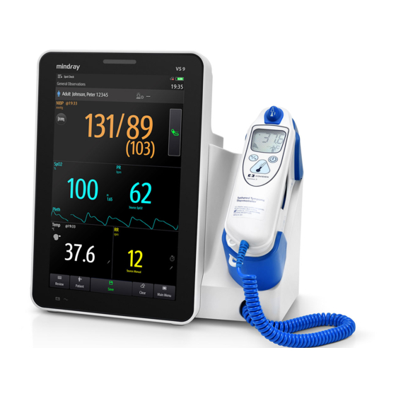
Measuring Temperature (Temp) 10.1 Temp Introduction The monitor can measure temperature with any one of the following temperature modules: ■ Mindray SmarTemp™ module ■ Convidien Genius™ 3 tethered tympanic thermometer ■ Exergen TemporalScanner™ thermometer ■ HeTaida Thermometer Below is a view of monitors configured with the above modules: SmarTemp™... -
Page 102: Monitoring Temp With Smartemp™ Module
Measurement site: displays the current measurement site. You can select this area to select another measurement site. Alarm off symbol if Temp alarm is off; alarm limit if Temp alarm is on Select this area to manually input a measured Temp value Temp reading Measurement mode (for SmarTemp only): displays the current mode, where “P”... -
Page 103: Measuring Temp
• Ensure that probe covers are disposed of according to local regulations or hospital's requirements. • Accuracy verification of the temperature module is required every two years or according to your hospital’s policy. Please contact our Customer Service if accuracy verification is needed. NOTE •... - Page 104 10.3.1.2 Taking a Temperature in Predictive Mode Verify that the probe is placed in the probe well. Verify that the temperature measurement type and site are correct. Unplug the probe from the probe well and the measurement mode changes to Predictive automatically.
-
Page 105: Disinfecting Temperature Probe
NOTE • In Predictive mode, temperature probe shall be placed to the measurement site as soon as probe warmup is complete; otherwise, inaccurate temperature reading may result. • In Predictive mode, if the probe has a high temperature due to the environmental temperature or other causes, cool the probe and then measure the patient's temperature. -
Page 106: Monitoring Temp With Genius™ 3 Tethered Tympanic Thermometer
WARNING • Perform the decontamination or cleaning process with the monitor powered down and power cord removed. • The used soft cloth shall be properly disposed of. 10.4 Monitoring Temp with Genius™ 3 Tethered Tympanic Thermometer The Genius™ 3 tethered tympanic thermometer is a fast, accurate, and convenient clinical instrument for measuring patient temperatures. -
Page 107: Equivalence Mode Temperature
Timer button Press and hold the timer button to enter the timer mode. Press again to start the timer. Scan button When the thermometer is on, press the scan button to initiate a temperature measurement. When the thermometer is off, press the scan button to turn on the device. -
Page 108: Troubleshooting
Place the probe in the ear canal. Once positioned lightly in the ear canal, press and release the scan button. Remove the probe from the ear as soon as the triple beep is heard. The temperature and probe eject icon display on the LCD screen. Press the eject button to eject the probe cover. -
Page 109: Safety Information
There are no parts that you can service yourself except for the battery, which you should replace when low by following the instructions in this manual. For service, repair, or adjustments, return your thermometer to Mindray. • No modification of this equipment is allowed. - Page 110 Temporal Artery Area Behind the Ear Alternate sites when temporal artery or behind ear are unavailable: ■ Femoral artery: slowly slide the probe across groin. ■ Lateral thoracic artery: slowly scan side-to-side in the area, midway between the axilla and the nipple. 10.5.2.2 Taking a Temperature on an Infant To take a temperature on an infant, follow this procedure: Place probe flush on center of forehead and depress button.
-
Page 111: Understanding The Temporalscanner™ Thermometer Led Display
LO A <60 °F (16 °C) Low Battery bAtt No or Very Low Battery blank display Processing Error Restart. Return to Mindray for repair if error message persists. Scanning (Normal - - - - Operation) 10.5.4 Fahrenheit or Celsius Conversion The TemporalScanner™... -
Page 112: Replacing The Battery
NOTE • After converting to Fahrenheit, the readings on TemporalScanner™ and the monitor might be slightly different. The readings on TemporalScanner™ would be more accurate. 10.5.5 Replacing the Battery To replace the battery, follow this procedure: Bend one leg of a paper clip and insert it into the pinhole in the side of the plastic housing. -
Page 113: Cleaning The Temporalscanner™ Thermometer
10.5.7 Cleaning the TemporalScanner™ Thermometer WARNING • Never use abrasive materials (such as steel wool or silver polish), or erosive cleaners (such as acetone or acetone-based cleaners). • Never immerse any part of the product in liquids or allow liquid to enter the interior. -
Page 114: Taking A Temperature With Hetaida Thermometer
You can manually input a Temp value and save the data for future reference. Follow this procedure: Select in the Temp area. For monitors configured with Mindray SmarTemp™ module, to input Temp value in Continuous Monitoring mode, press and hold in the Temp area. -
Page 115: Measuring Noninvasive Blood Pressure (Nibp)
Measuring Noninvasive Blood Pressure (NIBP) 11.1 NIBP Introduction The monitor uses the oscillometric method for measuring the non-invasive blood pressure (NIBP). NIBP measurement is based on the principle that pulsatile blood flow through an artery creates oscillations of the arterial wall. The oscillometric device uses a blood pressure cuff to sense these oscillations that appear as tiny pulsations in cuff pressure. -
Page 116: Nibp Safety Information
11.2 NIBP Safety Information WARNING • Be sure to select the correct patient category setting for your patient before NIBP measurement. Do not apply the higher adult settings for pediatric or neonatal patients. Otherwise, it may present a safety hazard. •... -
Page 117: Nibp Measurement Limitations
• Accuracy of NIBP measurement depends on using a cuff of proper size. It is essential to measure limb circumference and choose a cuff with proper size. 11.3 NIBP Measurement Limitations Measurement is impossible with heart rate extremes of less than 30 bpm or greater than 300 bpm, or if the patient is on a heart-lung machine. - Page 118 Time of last measurement NIBP unit Select this area to set the patient position and measurement site Systolic pressure Another measurement mode is available: ◆ If the department is set to Physician Office, swipe on the NIBP area to the left or right to switch to BP averaging screen.
-
Page 119: Preparing For Nibp Measurement
Mean pressure (displayed after measurement completed) or cuff pressure (dis- played during the measurement) Diastolic pressure Mean pressure alarm limits Start/Stop NIBP measurement Sequence information (for Sequence mode): the capital letter indicates the current phase and the time indicates the current measurement interval Diastolic pressure alarm limits Time to the next measurement (for Auto mode and Sequence mode) The display of pressure values can be configured. -
Page 120: Placing The Nibp Cuff
• The operator should not touch the cuff or tubing during NIBP measurement. • Other factors that have been shown to result in an overestimation of blood pressure are labored breathing, full bladder, pain etc. 11.6.2 Placing the NIBP Cuff To place the NIBP cuff, follow this procedure: Verify that the patient category setting is correct. -
Page 121: Performing Measurement
• Use care when placing the cuff on an extremity used for monitoring other patient parameters. 11.7 Performing Measurement This section describes the procedure to start manual, auto, STAT, and sequence measurement. For BP Averaging, see 11.9 BP Averaging. For Orthostatic BP measurement, see 11.10 Orthostatic BP Measurement. -
Page 122: Performing Stat Measurement
Prepare the patient and place the cuff as instructed in 11.6 Preparing for NIBP Measurement. Select a workflow under Continuous Monitoring. Select to set the patient position and measurement site. Select the NIBP numeric area to enter the NIBP menu. Set Interval to an appropriate duration. -
Page 123: Changing Nibp Settings
Set Start Mode to Interval. Select Start NIBP. 11.8 Changing NIBP Settings 11.8.1 Setting the NIBP Alarm Properties In Continuous Monitoring mode, you can set the NIBP alarm properties. Follow this procedure: Select the NIBP numeric area to enter the NIBP menu. Select the Alarm tab. -
Page 124: Setting The Nibp Display Format
11.8.5 Setting the NIBP Display Format To set the NIBP display format, follow this procedure: In Continuous Monitoring mode, select the NIBP numeric area to enter the NIBP menu. In Spot Check mode, select the Main Menu quick key → from the Parameters column select Setup →... -
Page 125: Setting Measurement Times
■ Patient having frequent arrhythmia ■ Weak patient pulse NOTE • The monitor always performs NIBP measurement at deflation stage if Patient Category is Neo. 11.8.8 Setting Measurement Times To set the measurement times, follow this procedure: Select the Main Menu quick key → from the Configuration column select Workflow →... -
Page 126: Bp Averaging Display
Under Average, enable BP Averaging. 11.9.2 BP Averaging Display The following figure shows the BP averaging screen. Time of last measurement NIBP unit Select this area to set the patient position and measurement site Averaged blood pressure: displayed in the form of Sys/Dia (Mean) Measurements used for averaging: if the first group of measurements is displayed with a strikethrough, it is excluded in the averaging. -
Page 127: Changing Bp Averaging Settings
11.9.4 Changing BP Averaging Settings 11.9.4.1 Setting the Delay before Starting the First Measurement Follow this procedure: Select the Main Menu quick key → from the Configuration column select Workflow → input the required password → select Select on the right of the workflow to be set. Make sure the workflow is under Spot Check. -
Page 128: 11.10 Orthostatic Bp Measurement
Select Parameters Setup → the NIBP tab. Under Average, enable Discard First Group of Readings. 11.10 Orthostatic BP Measurement Orthostatic blood pressure is important for the assessment of fall risks. On the monitor, you can measure the lying and standing blood pressure of a patient, and check the differences for clinical evaluation. -
Page 129: 11.10.3 Performing Orthostatic Bp Measurement
Evaluation result based on the set criteria: ◆ Negative: the differences are within the acceptable range as per the set criteria. ◆ Positive: the differences are out of the acceptable range as per the set criteria. For details, see 11.10.4.5 Setting Orthostatic BP Evaluation Criterion. Start/Stop standing blood pressure measurement before measurement and clear data after measurement Start/Stop lying blood pressure measurement... - Page 130 Select Parameters Setup → the NIBP tab. Under Orthostatic BP Measurement, set Lying Duration. 11.10.4.2 Setting Standing BP Measurement Interval Follow this procedure: Select the Main Menu quick key → from the Configuration column select Workflow → input the required password → select Select on the right of the workflow to be set.
-
Page 131: 11.11 Assisting Venous Puncture
The NIBP leakage test checks the integrity of the system and of the valve. The NIBP leakage test should be performed once every two years or when you doubt the NIBP measurements. The NIBP leakage test should be performed by Mindray-qualified service personnel only. -
Page 132: 11.12.2 Nibp Accuracy Test
11.12.2 NIBP Accuracy Test The NIBP accuracy test should be performed once every two years or when you doubt the NIBP measurements. The NIBP accuracy test should be performed by Mindray- qualified service personnel only. 11.13 NIBP Troubleshooting For more information, see D Alarm Messages. -
Page 133: Monitoring Co
The CO measurement is to monitor the patient’s respiratory status. monitoring is intended for adult, pediatric and neonatal patients. monitoring is for VS 9 series only. measurement is available when the monitor is in Continuous Monitoring mode. 12.2 Safety WARNING •... -
Page 134: Measurement Limitations
12.3 Measurement Limitations The following factors may influence the measurement accuracy: ■ Leaks or internal venting of sampled gas ■ Mechanical shock ■ Cyclic pressure up to 10 kPa (100 cmH ■ Other sources of interference, if any Measurement accuracy may be affected by the breath rate and inspiration/expiration ratio (I: E ratio) as follow: ■... -
Page 135: Measuring Co
12.5 Measuring CO CAUTION • Eliminate the exhausted gas before performing the measurement. • Connect an exhaust tube to the gas outlet connector of the monitor to vent the calibration gases to a scavenging system. • Check that the alarm limit settings are appropriate before taking measurement. -
Page 136: Automatic Co Module Zeroing
Connect the CO gas outlet to the scavenging system with an exhaust tube. can be measured after the start-up is complete. NOTE • When sample gas of 37 °C, sample flowrate of 50 ml/min, room temperature of 23 °C, 100% RH, the sampling line with a general type should be replaced once at most every 8 hours, and the sampling line with a humidified type should be replaced once at most every 72 hours. -
Page 137: Setting The Co Waveform
12.7.2 Setting the CO Waveform In Continuous Monitoring mode, you can set the CO waveform. Follow this procedure: Select the CO numeric area or waveform area to enter the CO2 menu. Select Setup tab. Set Waveform Type, Speed and CO2 Scale of the CO waveform. -
Page 138: Setting Gas Compensation
× ⁄ ■ ATPD: P co2 mmHg CO 2 vol% P amb 100 × ⁄ ) 100 – ■ BTPS: P co2 mmHg CO 2 vol% P amb 47 Where, = partial pressure, = CO concentration, = ambient pressure, and unit is mmHg. To set the humidity compensation, follow this procedure: Select the CO numeric area or waveform area to enter the CO2 menu. -
Page 139: Monitoring Respiration
Respiration monitoring is not for use on the patients who are very active, as this will cause false alarms. 13.2 RR Display The RR parameter area displays its source. Sourced from CO Sourced from Mindray SpO RR: Respiration rate per minute 13 - 1... -
Page 140: Measurement Limitations Of Spo2-Sourced Rr
RR unit RR high limit RR low limit RR Source: it can be SpO , CO or Manual. Select to input RR manually: displays only in Spot Check mode, or when CO is not configured. 13.3 Measurement Limitations of SpO2-Sourced RR The following factors may influence the accuracy of RR measurement sourcing from ■... -
Page 141: Setting Rr Alarms
Switch on RR. 13.5.3 Setting RR Alarms In Continuous Monitoring mode, you can set the RR alarm limits. Follow this procedure: Select the CO numeric area or waveform area to enter the CO2 menu. Select Alarm tab. Set the high and low limits and the priority in the RR row. 13.5.4 Setting the Apnea Alarm Delay The monitor will alarm if the patient has stopped breathing for longer than the preset... - Page 142 This page intentionally left blank. 13 - 4...
-
Page 143: Manual Parameters
Manual Parameters The monitor supports inputting physiological information of a patient manually for clinical evaluation and record. The information can be saved for future reviewing, printing, or sending to other devices. 14.1 Manual Input Parameters Below is a list of manual parameters provided by default: ■... -
Page 144: Inputting/Editing Parameter Information
* symbol: indicates the parameter can be used for EWS calculation. Parameter name Parameter setup area: select to input a value, show the options, or a setup menu. If you need to change the parameters to be displayed or their sequence in the list, refer to 14.4.1 Changing the Display of Manual Parameters. -
Page 145: Changing Manual Input Settings
Select the Save quick key to save the data. NOTE • The input information can be reviewed, printed or sent to other devices only after being saved. If not saved, the information may be lost after a patient is discharged or workflow is switched. 14.4 Changing Manual Input Settings 14.4.1... - Page 146 After saving the setting, you can follow the procedure in 14.4.1 Changing the Display of Manual Parameters to add the new parameter to the Manual Input list displayed on the screen. 14 - 4...
-
Page 147: Clinical Assistive Applications (Caa)
MEWS, NEWS and NEWS2 are intended for adult patients only. The patient category applied to the Custom Score is defined by Mindray Clinical Score Configuration Tool. For more information, see Mindray Clinical Scoring Config Tool Instruction for Use (P/N: 046- 007126-00). -
Page 148: The Ews Display
WARNING • EWS should not be used as the sole basis for diagnosis or therapy decisions. It is not intended to replace the competent judgment of a clinician.The EWS scores and recommended actions must be used in conjunction with observation of clinical signs and symptoms. •... -
Page 149: Accessing The Ews Screen
15.1.2 Accessing the EWS Screen Access the EWS window in any of the following ways: ■ Select the EWS parameter area Select the Main Menu quick key → from the CAA column select EWS. ■ Take NEWS2 as an example, the EWS screen is shown as follows. Your screen may be slightly different due to the configuration. -
Page 150: Ews Scoring In Spot Check Mode
Subscore area: display the subscore of each parameter. Keyboard symbol: indicates that the value is manually entered. Selecting this button to see the clinical response to the current score. Scoring interval (available in Continuous Monitoring mode) Scoring countdown (available in Continuous Monitoring mode): time to the next scoring. -
Page 151: Ews Alarm
NOTE • The decision to use Scale 2 of the SpO2 Scale should be made by a competent clinical decision maker and should be recorded in the patient’s clinical notes. • Before calculating the score, select Reset to clear the previous score. •... -
Page 152: Changing Ews Settings
■ The total score exceeds the configured threshold ■ The score of auto obtained parameter is 3. To configure the EWS alarm, follow this procedure: From the EWS page select Setup. Select the Alarm tab. Turn on the Alarm switch. Set the alarm switches for the single parameters listed in the 3 in single parameter area. -
Page 153: Viewing History Scores
◆ On: you need to confirm that whether the scoring result is saved or not after the scoring is completed. 15.1.6.3 Setting the Manual Data Timeout The manually input parameter data become invalid after a preset time. To set the timeout period for the input data, follow this procedure: From the EWS screen select Setup. -
Page 154: Glasgow Coma Scale (Gcs)
• The monitor provide MEWS, NEWS, and NEWS2 by default. You cannot delete them. • For details about how to import scoring tools, refer to Mindray Clinical Scoring Config Tool Instruction for Use (P/N: 046-007126-00). 15.2 Glasgow Coma Scale (GCS) The Glasgow Coma Scale (GCS) function is based on 1974_Lancet_ Teasdale Assessment of Coma and Impaired Consciousness-A Practical Scale. -
Page 155: Gcs Display
15.2.1 GCS Display The GCS value displays in the Manual Input list, as shown below: GCS label GCS value: total score. Select this area to enter the GCS menu. Your display may look slightly different. If GCS is not displayed, you can follow the procedure in 14.4.1 Changing the Display of Manual Parameters to add GCS to the list. -
Page 156: Accessing The Gcs Menu
15.2.2 Accessing the GCS Menu Select the GCS value to enter the GCS menu. Subscores Total score and level of consciousness. The color of the circle indicates the level of risk. Scoring time 15.2.3 Performing GCS Scoring To perform scoring, follow this procedure: 15 - 10... -
Page 157: Setting Threshold For Each Consciousness Level
From the Eye Opening area, Verbal Response area, and Motor Response area, respectively select an item that represents the patient’s status. Select OK to accept the total score. Select the Save quick key to save GCS scoring. The following table lists the default score range and color of relevant consciousness level. -
Page 158: The Pain Score Display
■ FPS-R: face pain scale revised. ■ FLACC: stands for face, legs, activity, crying, and consolability. You can also add custom pain scores to the list. For details, refer to 15.3.3 Adding a Custom Pain Scale. Pain Score is applicable for adult, pediatric, and neonatal patients. 15.3.1 The Pain Score Display The following figure shows the pain score screen. -
Page 159: Adding A Pain Description
Under Custom Pain Score Method, select corresponding area to edit the name of your scale, and change the upper limit of scoring value. Enable Display on the right of the pain score for it to be displayed on the Pain Score screen. -
Page 160: The Display Of The Targeted Goal Screen
15.4.2 The Display of the Targeted Goal Screen Target parameter area: displays the SpO measurement in big numerics, as well as its target range, and alarm limits. ◆ The dashboard shows the target range in green. ◆ The △ pointer below the dashboard indicates the current measurement value. - Page 161 ■ Select the desired waveform area, parameter numeric area, or dashboard to enter corresponding parameter setup menu. 15.4.3.1 Statistics Display The following figure shows the SpO statistics area: Duration of SpO statistics Results of SpO statistics Sections for statistics: The section in green indicates the target range. 15.4.3.2 Selecting the Range of each SpO Section and the Target Section To define the SpO...
- Page 162 This page intentionally left blank. 15 - 16...
-
Page 163: Recording
Recording 16.1 Recorder The thermal recorder records patient information, measurement data, and up to two waveforms. The monitor can be configured with a built-in recorder. Start/Stop key: press to start a recording or stop the current recording. Module status indicator ◆... -
Page 164: Stopping Recordings
■ Select on the current page. In Spot Check mode, to start a recording: Select the Save quick key. Select on the current page. 16.3 Stopping Recordings Recordings can be stopped manually or automatically. 16.3.1 Stopping Recordings Manually To manually stop a recording, choose either of the following method: ■... -
Page 165: Loading Paper
16.6 Loading Paper To load paper, follow this procedure: Use the latch at the upper right of the recorder door to pull the door open. Insert a new roll into the compartment as shown below. Feed the paper through and pull some paper out from the top of the roller. Close the recorder door. - Page 166 This page intentionally left blank. 16 - 4...
-
Page 167: Review
Review 17.1 Review Overview Trends are patient data collected over time and displayed in graphic, tabular, or other forms to give you a picture of how your patient's condition is developing. You can also review the events, scores, and so on. 17.2 Review Page The Review page contains tabs to display trend data in tabular, graphic, or other forms. -
Page 168: Reviewing The Tabular Trends
Record button: select it to output patient information and data through the recorder. Current window time line: indicates the time length of the current window. Waveform area: displays trend curves. The color of trend curves is consistent with the color of parameter labels. Zoom: select the time duration of data to be viewed on one screen. -
Page 169: Reviewing The Graphics Trends
Select the Review quick key → select Scoring Review tab. Set the filtering condition to PID, Name, or Visit No.. Then select the information of the patient to be viewed. Set Filter to MEWS, NEWS or NEWS2. Select a record to be viewed and select Detail to check more information. 17.2.5 Reviewing the Graphics Trends The Graphic Trends review page displays trend data in a graphic form. - Page 170 The number of asterisk symbols before and event matches alarm priorities as follows: ■ ***: high priority alarm ■ **: medium priority alarm ■ *: low priority alarm NOTE • Pausing or switching off alarms will not be recorded as events. The time of these operations will not be recorded in the system log.
-
Page 171: User Maintenance Settings
User Maintenance Settings User maintenance enables you to customize your equipment to best meet your needs. Accessing the Maintenance menu is password protected. This chapter describes the settings and functions in the Maintenance menu. CAUTION • The maintenance settings can only be changed by authorized personnel. Contact your department manager or biomedical engineering department for the passwords used at your facility. -
Page 172: The Patient Management Settings
Default Menu Item Function Setting Auto Obtain Bed No. The setting is available if Location is set to Unfixed. NOTE • If Location is set to are cleared each time you Unfixed Bed No Room No discharge a patient. 18.3 The Patient Management Settings 18.3.1 The Patient Field Tab... -
Page 173: The Adt Query Tab
18.3.2 The ADT Query Tab Menu Item Default Setting Function ADT Query Patient ID, Selects which criteria can be used to search Patient Name patients in the ADT server 18.3.3 The Discharge Tab Menu Item Default Setting Function Auto Discharge Never Automatically discharges the patient when Patient If Powered... -
Page 174: The Authorization Setup Tab
18.4.2 The Authorization Setup Tab Default Section Menu Item Function Setting Maintenance User Local Selects the password for accessing the Maintenance Password monitor’s Maintenance menu. • Local Password: the monitor’s password for accessing the Maintenance menu is required. • Clinician Authentication: the user name and password saved in the MLDAP server are required. -
Page 175: The Save&Send Tab
Default Section Menu Item Function Setting Clinic Modify Local Changes the monitor’s password for Password accessing alarm settings. 18.5 The Save&Send Tab Default Section Menu Item Function Setting Save Options Confirm Before Saving Selects whether confirmation is needed before saving physiological data. -
Page 176: The Alarm Tab
Default Section Menu Item Function Setting Send Options Clinician Required Selects whether clinician login is needed before sending data. Clinician Match Selects whether data can be Required sent if clinician information does not match with the information in database. Clear Sent Data After Selects whether to clear data Sending after sending. -
Page 177: The Pause/Reset Tab
Menu Item Default Setting Function Auto Increase 2 Steps • 2 Steps: if an alarm is not reset within the Volume designated delay time after the alarm occurs, the alarm volume automatically increases by two levels. • 1 Step: if an alarm is not reset within the designated delay time after the alarm occurs, the alarm volume automatically increases by one level. - Page 178 Default Section Menu Item Function Setting Pause Priority Selects alarms of what priority can be Pause paused. • All: pressing the Alarm Pause quick key pauses all alarms. • Med & Low: pressing the Alarm Pause quick key pauses alarms of medium and low priority.
-
Page 179: The Latching Tab
Default Section Menu Item Function Setting Reminder 5 min • 10 min: the monitor issues reminder Reminder Interval tones every 10 minutes. Tone • 5 min: the monitor issues reminder tones every five minutes. • 3 min: the monitor issues reminder tones every three minutes. -
Page 180: The Other Tab
Menu Item Default Setting Function Alarm Priority High Only Selects the priority of alarms sent to the nurse call system Alarm Type Physiological Selects the type of alarms sent to the nurse call Only system. 18.6.5 The Other Tab Default Section Menu Item Function... -
Page 181: The Standby Settings
Default Section Menu Item Function Setting CMS/eGW Selects whether an alarm is issued when Other Disconnected the monitor is not connected or Alarm disconnected from the CMS/eGateway. Off: the “Offline” alarm is not presented when the monitor is not connected or disconnected from the CMS/eGateway. -
Page 182: The Gcs Tab
18.8.2 The GCS Tab Menu Item Default Setting Function Mild High Selects the threshold and color of each consciousness level. Color White Moderate High Color Yellow Severe High Color 18.9 The Module Settings 18.9.1 The NIBP Tab Menu Item Default Setting Function NIBP Measurement Inflation... -
Page 183: The Co2 Tab
Menu Item Default Setting Function Orthostatic BP Dizziness/Visual Edits the provided symptoms. Symptoms Disturbance/ Available only when the monitor is in Spot Light- Check mode. Headedness/ Feeling of Weakness/ Vagueness/ Palpitation/Pallor Add Symptom To add new symptoms. Available only when the monitor is in Spot Check mode. -
Page 184: The Temp Tab
18.9.3 The Temp Tab Menu Item Default Setting Function Temp Selects the type of Temp module. Temp Measurement Ear/Temporal / Sets the options displayed in the Site Oral/Axillary Measurement Site menu. 18.9.4 The Manual Input Tab This menu lists the manual parameters currently supported on the monitor. You can also add other parameters to the list. -
Page 185: 18.10 The Unit Settings
18.10 The Unit Settings Menu Item Default Setting Description Height Unit Selects measurement unit for each parameter. Weight Unit Glucose Unit mg/dl I/O Fluid Unit CO2 Unit mmHg Temp Unit °C Pressure Unit mmHg 18.11 The Time Settings 18.11.1 The Time Synchronization Tab Default Section Menu Item... -
Page 186: 18.11.2 The Daylight Savings Time Tab
18.11.2 The Daylight Savings Time Tab Default Section Description Setting Auto Daylight Savings Time On: auto starts the daylight savings time. 18.12 The Version Tab Default Setting Function Version Displays system software version, module hardware and software version, and firmware version. 18.13 The Battery Information Settings Default Setting Function... -
Page 187: 18.14.2 The Jadak Barcode Tab
Function Patient Category Sets the information of JADAK barcode. Gender Month 18.14.3 The Identify Scanner Tab (for the non-Mindray Custom 2D Barcode Reader) Default Setting Function Identify Scanner When you are using barcode readers other than HS-1R or HS-1M, you should select the barcode reader from the USB device list, so that the monitor can identify the barcode reader. -
Page 188: The Field Tab (For The Mindray Custom 2D Barcode Reader)
18.14.4 The Field Tab (for the Mindray Custom 2D Barcode Reader) Menu Item Default Setting Function Patient ID/First Name/Last Name/ Selected Selects desired patient Patient Category/Gender/DOB information to be output by the barcode reader. Visit Number/Room No/Bed No/ Unselected Age/Department/Custom Field 1 - Custom Field 4 18.15 The Record Settings... -
Page 189: 18.16.3 The Wlan Tab
Menu Item Default Setting Function Using the Following DNS Address IP addresses of Preferred DNS Server and Alternate DNS Server are required. 18.16.3 The WLAN Tab Default Menu Item Function Setting Available Network List Lists the available network currently detected. Add WLAN WLAN Sets the Name, SSID, Security... -
Page 190: 18.16.5 The Transfer Setup Tab
Menu Item Default Setting Function Obtain DNS address Selects whether to enable the function of automatically automatically getting the DNS address. Using the Following Selects whether inputting the IP address of DNS Address Preferred DNS Server and Alternate DNS Server is required. 18.16.5 The Transfer Setup Tab Menu Item Default Setting... -
Page 191: 18.16.6 The Device Discover Tab
Menu Item Default Setting Function Alarms Server Address Inputs the name or IP address for the server receiving the alarm data. Destination IP 0.0.0.0 Port Send Alarms Connection Disconnected Status Data + Waveforms and Alarms are for HL7 setup. You can send the realtime data, waveforms, and alarms from the monitor to the hospital servers via HL7 protocol. -
Page 192: 18.16.7 The Qos Tab
Menu Item Default Setting Function Network Test Tests whether the master server is properly connected. 18.16.7 The QoS Tab Default Menu Item Function Setting QoS Level For Selects the service quality of network Realtime connection for realtime monitoring, for Monitoring example parameter measurements and waveforms, alarms, and so on QoS Level For... -
Page 193: 18.17 The Bluetooth Tab
Default Section Menu Item Description Setting General Master Server Sets the connection Connectivity Address information. Context Root Organization ID Local CSI Security Auth Type Basic Sets the security information. User Name User Password Tenant Type None Tenant Value Transport Protocol HTTP Barcode Format Data Encoding... -
Page 194: 18.18 The Other Tab
18.18 The Other Tab Menu Item Default Setting Function Barometric Pressure 760 mmHg Sets the barometric pressure. SpO2 Tone Mode 1 Selects the SpO tone. The same SpO tone mode should be used for monitors in the same area. Clear CMS IP at startup Language Parameter Output Setup Configures DIAP protocol parameters... -
Page 195: Battery
Battery 19.1 Overview This monitor is designed to operate on battery power when the mains power is not available. The monitor uses mains power as primary power source. In case of mains power failure, the monitor automatically runs on the battery power. 19.2 Battery Safety Information WARNING... -
Page 196: Battery Indications
19.3.1 Battery LED The battery LED is on the left bottom of the front panel of the monitor. For details, see 2.7.1 Front View (VS 9 Series) and 2.7.2 Front View (VS 8 Series). 19.3.2 Battery Symbols The on-screen battery symbols indicate the battery status as follows: ■... -
Page 197: Battery-Related Alarms
19.4 Replacing the Battery (for VS 9 Series) For VS 9 series, to replace the battery, follow this procedure: Turn off the monitor. Disconnect the power cable and other cables. Lay the monitor down to expose the bottom of the monitor. -
Page 198: Replacing The Battery (For Vs 8 Series)
19.5 Replacing the Battery (For VS 8 Series) For VS 8 series, to replace the battery, follow this procedure: Turn off the monitor. Disconnect the power cable and other cables. Lay the monitor down to expose the bottom of the monitor. Open the battery compartment door. -
Page 199: Connecting An External Battery
19.6 Connecting an External Battery You can connect an external battery to the monitor via the connector on the back. VS 9 Series VS 8 Series Connector for an External Battery The external battery is charged whenever the monitor is connected to an AC power source regardless of whether or not the monitor is currently on. -
Page 200: Checking Battery Performance
Connect the monitor to AC power. Fully charge the battery again for use or charge it to 40 – 60% for storage. NOTE • Do not use the monitor to monitor the patient during battery conditioning. • Do not interrupt battery conditioning. 19.8.2 Checking Battery Performance Life expectancy of a battery depends on how frequent and how long it is used. -
Page 201: 19.10 Recycling Batteries
• Storing batteries in a cool place can slow the aging process. Ideally the batteries should be stored at 15 °C. 19.10 Recycling Batteries Discard a battery in the following situations: ■ The battery has visual signs of damage. ■ The battery fails. - Page 202 This page intentionally left blank. 19 - 8...
-
Page 203: Care And Cleaning
20.2 Care and Cleaning Safety Information WARNING • Use only Mindray approved cleaners, disinfectants and methods listed in this chapter to clean or disinfect your equipment or accessories. Warranty does not cover damage caused by unapproved substances or methods. •... -
Page 204: Cleaning And Disinfecting The Main Unit
• Dilute and use the cleaners or disinfectants according to the manufacturer's instructions. • Check the equipment after cleaning and disinfecting. If there is any sign of damage, remove it from use. 20.3 Cleaning and Disinfecting the Main Unit 20.3.1 Cleaning the Main Unit Clean the monitor on a regular basis. - Page 205 Product Name Product Type Manufacturer Clorox Dispatch® Wipes Clorox professional products Hospital Cleaner Disinfectant company Towels with Bleach Clorox Healthcare® Bleach Wipes Clorox professional products Germicidal Wipes company Clorox Healthcare® Hydrogen Wipes Clorox professional products Peroxide Cleaner Disinfectant company Wipes Diversey Oxivir®...
- Page 206 Product Name Product Type Manufacturer DIAN’ERKANG® Disinfection Liquid, spray Shanghai Likang Disinfectant Hi- Spray Tech Co., Ltd. Clinell® Universal Wipes GAMA Healthcare Ltd Wipes Clinell ® Sporicidal Wipes GAMA Healthcare Ltd Wipes Tristel Duo™ Liquid, spray Tristel solutions Limited Tristel Jet Liquid, spray Tristel solutions Limited Tristel Fuse...
-
Page 207: Cleaning And Disinfecting The Accessories
Never clean or disinfect the connectors and metal parts. • Use only Mindray approved cleaners and disinfectants and methods listed in this section to clean or disinfect the accessories. Warranty does not cover damage caused by unapproved substances or methods. -
Page 208: Cleaning And Disinfecting Agents For The Nibp Air Hose
20.4.1 Cleaning and Disinfecting Agents for the NIBP Air Hose The following table lists approved cleaning and disinfecting agents for the NIBP air hoses: Product Name Product Type Manufacturer Alpet® D2 Wipes BEST SANITIZERS INC™. Surface Sanitizing Wipes CIDEXR OPA Liquid Gilag GmbH International Advanced Sterilization products... -
Page 209: Cleaning And Disinfecting Agents For The Spo
20.4.2 Cleaning and Disinfecting Agents for the SpO Cable The following table lists approved cleaning and disinfecting agents for the Masimo cables: Product Name Product Type Manufacturer Isopropanol, 70% Liquid The following table lists approved disinfectants for the Nellcor SpO cables: Product Name Product Type... -
Page 210: Cleaning The Accessories
20.4.3 Cleaning the Accessories You should clean the accessories (NIBP air hose, and SpO cable) on a regular basis. Before cleaning the accessories, consult your hospital’s regulations for cleaning the accessories. To clean the accessories (NIBP air hose and SpO cable), follow this procedure: Clean the accessories with a soft cloth moistened with water or ethanol (70%). -
Page 211: Maintenance
Maintenance 21.1 Maintenance Introduction Regular maintenance is essential to ensure that the equipment functions properly. This chapter contains information on periodic testing and maintenance. 21.2 Maintenance Safety Information WARNING • To avoid electric shock, stop using the monitor if you find the housing of the monitor has signs of broken. -
Page 212: Maintenance And Testing Schedule
The equipment and accessories shall not be served or maintained while in use with a patient. • If you discover a problem with any of the equipment, contact your service personnel or Mindray. • Use and store the equipment within the specified temperature, humidity, and altitude ranges. -
Page 213: Checking Version Information
You can check system software version, module hardware and software version, and firmware version. 21.5 Testing Methods and Procedures Except the following maintenance tasks, all other test and maintenance tasks should be performed by Mindray-qualified service personnel only. ■ Regular check, including visual inspection and power-on test ■ Recorder test ■... -
Page 214: Performing Visual Inspection
If your monitor needs a safety test and performance test, contact the service personnel. 21.5.1 Performing Visual Inspection Visually inspect the equipment before its first used every day. If you find any signs of damage, remove your monitor from use and contact the service personnel. Verify that the equipment meets the following requirements: ■... -
Page 215: Accessories
Accessories The accessory material that contacts the patients or other staff has undertaken the bio- compatibility test and is verified to be in compliance with ISO 10993-1. For details about the accessories, refer to the instructions for use provided with the accessory. -
Page 216: Spo Extension Cable
22.1.1 Extension Cable Applicable Module type Remarks Part No. Usage patient Mindray SpO 7 pins, 2.5 m 0010-20-42710 Reusable Module 7 pins, 1.2 m 040-001443-00 Reusable Masimo SpO 8 pins, 2.1 m 040-000332-00 Reusable Module 8pin masimo 040-005973-00 Reusable Cable(RD SET) - Page 217 Applicable Application Model Patient Category Part No. patient site 512F Reusable SpO Sensor 512F-30-28263 Adult Finger 512FLH Reusable SpO Sensor 115-012807-00 Adult Finger 512G Reusable SpO Sensor 512G-30-90607 Pediatric Finger 512H 512H-30-79061 Pediatric Finger Reusable SpO Sensor 22.1.3 Masimo SpO Sensors Applicable Application...
-
Page 218: Nibp Accessories
22.2 NIBP Accessories 22.2.1 NIBP Hoses Model Usage Patient Category Part No. CM1903 Reusable Adult, pediatric, neonate 6200-30-09688/115- 012522-00 CM1908 040-002712-00 22.2.2 Reusable NIBP Cuffs Model Patient Measurement Limb Circumference Part No. Category Site (cm) CM1200 Small Infant 7 to 13 115-002480-00 CM1201 Infant... -
Page 219: Disposable Nibp Cuffs
22.2.3 Disposable NIBP Cuffs Patient Measurement Limb Model Part No. Category Site Circumference (cm) CM1500A Neonate 3.1 to 5.7 125-000046-00 CM1500B 4.3 to 8.0 125-000047-00 CM1500C 5.8 to 10.9 125-000048-00 CM1500D 7.1 to 13.1 125-000049-00 CM1500E 8 to 15 125-000050-00 CM1501 Infant 10 to 19... -
Page 220: Genius™ 3 Tympanic Thermometer Accessories
Model Usage Description Part No. MR491 Reusable Blue, oral/axillary M09A-20-62062 MR492 Red, Rectal M09A-20-62062-51 Temp Probes Measurement Model Description Patient Category Part No. Site MR431 Reusable, Adult, Pediatric, Neonate Oral/Axillary 6006-30-39598 MR432 Adult, Pediatric Rectal 6006-30-39599 MR431 Reusable, Adult, Pediatric, Neonate Oral/Axillary 6006-30-39600 package... -
Page 221: Hetaida Thermometer
22.3.4 HeTaida Thermometer Model Usage Description Part No. HTD8808C Reusable Non-contact Infrared Thermometer 100-000446-00 22.4 Accessories Model Part No. Description Applicable patient XS04620 0010-10-42560 Disposable airway sampling line Adult/Pediatric XS04624 0010-10-42561 Disposable airway sampling line, Adult/Pediatric humidified 006324 0010-10-42562 Disposable airway sampling line, Neonatal humidified 007768... - Page 222 Model Part No. Description Applicable patient 008181 0010-10-42576 Disposable nasal sampling line, Pediatric humidified, plus O 008174 0010-10-42577 Disposable nasal sampling line Adult 008175 0010-10-42578 Disposable nasal sampling line Pediatric MVIIHL 040-006160-00 Intubated CO FilterLine Neonatal/Infant MVAIHL 040-006161-00 Intubated CO FilterLine Adult/Pediatric MVAIL...
-
Page 223: Others
22.5 Others Description DA8K-10-14454 Power cord, Europe DA8K-10-14453 Power cord, UK DA8K-10-14452 Power cord, USA 509B-10-05996 Power cord, 10 A, 250 V, 1.6 m, China 009-001075-00 Power cord, 10 A, 250 V, 3 m, Brazil 009-001791-00 Power cord, 250 V, 16 A, 3 m, South Africa 009-007190-00 Power cord, 3 m, India 009-007191-00... - Page 224 This page intentionally left blank. 22 - 10...
-
Page 225: A Product Specifications
Product Specifications Classifications The equipment is classified, according to IEC60601-1: Type of protection against CLASS I EQUIPMENT, equipment energized from an electrical shock external and internal electrical power source. Degree of protection against DEFIBRILLATION-PROOF TYPE CF AAPPLIED PART for electrical shock , NIBP, and SmarTemp™... -
Page 226: Smartemp™ Temperature Module
A.2.2 SmarTemp™ Temperature Module Item Operating conditions Storage conditions Temperature 5 ºC to 40 ºC Same as the main unit Relative humidity (non- Same as the main unit Same as the main unit condensing) Barometric Same as the main unit Same as the main unit A.2.3 Genius™... -
Page 227: Power Supply Specifications
100 to 240 VAC (±10%) Current 0.9 to 0.5 A Frequency 50/60 Hz (±3 Hz) Fuse T2AL-250V A.3.2 Battery Specifications of VS 9 Series Battery Type Rechargeable lithium-Ion battery Voltage 10.8 VDC Capacity 5600 mAh Run time At least 8 hours when powered by a new, fully-charged battery at 25 °C ±5 °C on standard configuration (SpO... -
Page 228: Battery Supply Specifications Of Vs 8 Series
NIBP module, recorder module and a NIBP module, recorder module and a 5000 mAh battery; without capacitive battery; without accessory) screen; without accessory) Hardware Specifications A.5.1 Display Specifications of VS 9 Series Screen type Color TFT LCD Screen Size (diagonal) 10.1” Resolution 1280×800 pixels A.5.2... -
Page 229: Recorder Specifications
Resolution 1024×768 pixels A.5.3 Recorder Specifications Method Thermal dot array Paper speed 25 mm/s A.5.4 LEDs Alarm lamp 1 (three color coded: cyan, yellow and red) Power on LED 1 (green) AC power LED 1 (green) Battery LED 1 (two color coded: yellow and green) A.5.5 Audio Indicator Speaker... -
Page 230: Wi-Fi Technical Specifications
Alarm delay time from The alarm delay time form the monitor to remote equipment is monitor to remote ≤2 seconds, measured at the monitor’s signal output connector. equipment A.5.8 Wi-Fi Technical Specifications Standards IEEE 802.11a/b/g/n/ac Modulation mode BPSK, QPSK, 16QAM, 64QAM, 256QAM Operating 2412MHz~2472MHz, frequency... -
Page 231: A.5.10 Blue Tooth Specification
A.5.9.2 Resistance to Wireless Interference The distance between the interfering devices and the monitor is greater than 20 cm. A Wi-Fi interference (no greater than -85 dBm) in the same channel and a Wi-Fi interference (no greater than -50 dBm) in an adjacent channel are presented synchronously. -
Page 232: Measurement Specifications
Range (%) Step (%) High (low limit + 2) to 100 Mindray, Masimo: (Desat +1) to (high limit – 2) Nellcor: (Desat+1) or 20 (whichever is greater) to (high limit – 2) Desat 0 to (low limit – 1) A.6.1.1... - Page 233 PI Resolution PI < 10.0: 0.01 PI ≥ 10.0: 0.1 Accuracy 70 to 100%: ±2% ABS (adult/pediatric) 70 to 100%: ±3% ABS (neonate) 0% to 69%: Not specified. *Studies were performed to validate the accuracy of Pulse Oximeter with neonatal SpO sensors by contrast with a CO-Oximeter.
- Page 234 Low perfusion conditions Pulse amplitude: >0.02% Light penetration: >5% Low perfusion SpO ±2% accuracy The Masimo pulse oximeter with sensors have been validated for no motion accuracy in human blood studies on healthy adult volunteers in induced hypoxia studies in the range of 70% to 100% SpO against a laboratory co-oximeter and ECG monitor.
- Page 235 PR > 40: (low limit +5) to 300 PR > 40: 5 PR Low PR ≤ 40: 15 to (high limit - 2) PR > 40: 40 to (high limit - 5) A.6.2.1 PR from Mindray SpO Module Measurement range 20 to 300 bpm Resolution 1 bpm Response time <...
-
Page 236: Nibp
The Masimo pulse oximeter has been validated for low perfusion accuracy in bench top testing against a Biotek Index 2 simulator and Masimo's simulator with signal strengths of greater than 0.02% and a % transmission of greater than 5% for saturations ranging from 70 to 100%. - Page 237 Measurement ranges Adult Pediatric Neonate (mmHg) Systolic: 25 to 290 25 to 240 25 to 140 Diastolic: 10 to 250 10 to 200 10 to 115 Mean: 15 to 260 15 to 215 15 to 125 ± Accuracy Max mean error: 5 mmHg Max standard deviation: 8 mmHg Static pressure...
-
Page 238: Temp Specifications
Sys High Adult: (low limit+5) to 290 ≤ 50: 1 Pediatric: (low limit+5) to 240 > 50: 5 Neonate: (low limit+5) to 140 Sys Low 25 to (high limit-5) Mean High Adult: (low limit+5) to 260 Pediatric: (low limit+5) to 215 Neonate: (low limit+5) to 125 Mean Low 15 to (high limit-5) - Page 239 Resolution 0.1 °C Minimum measurement Monitor mode: <60 s time for accurate readings Predictive mode: <20 s (typical test:< 12 s) Alarm limit Range Step Temp High (low limit +1) °C to 44 °C 0.1 °C Temp Low 25 °C to (high limit -1) °C Statistical Results of Clinical Investigation Data Limits of Agreement Clinical...
-
Page 240: Specifications
A.6.5 Specifications Standard Meet standard of ISO 80601-2-55 Technique Infrared absorption Apnea delay 10 s, 15 s, 20 s, 25 s, 30 s, 35 s, 40 s Measurement 0 to 150 mmHg range Accuracy Full accuracy mode: 0 to 40 mmHg: ±2mmHg 41 to 76 mmHg: ±5% of reading 77 to 99 mmHg: ±10% of reading 100 to 150mmHg: ±(3mmHg + 8% of reading) -
Page 241: Rr Specifications
Neonate: (low limit + 5) to 150 rpm RR Low RR ≤ 20 rpm: 0 to (high limit – 2) rpm RR >20 rpm: 20 to (high limit – 5) rpm A.6.6.1 RR from Mindray CO Module Measurement range 0 to 150 rpm Measurement precision <60 rpm: ±1 rpm... -
Page 242: Operating Environment
Operating Environment Host CPU AM3358 Primary programming language Operating system Linux 3.2.0 A - 18... -
Page 243: B Emc And Radio Regulatory Compliance
EMC and Radio Regulatory Compliance The device meets the requirements of IEC 60601-1-2: 2014. NOTE • Use of accessories, transducers and cables other than those specified or provided by the manufacturer of this device could result in increased electromagnetic emissions or decreased electromagnetic immunity of this device and result in improper operation. - Page 244 Guidance and Declaration – Electromagnetic Emissions The device is intended for use in the electromagnetic environment specified below. The customer or the user of the device should assure that it is used in such an environment. Electromagnetic environment – Emission tests Compliance guidance Conducted and radiated RF...
- Page 245 NOTE • If the essential performance is lost or degraded, it may be necessary to take mitigation measures, such as re-orienting or relocating the ME EQUIPMENT or ME SYSTEM or shielding the location or stopping using the monitor and contact the service personnel. •...
- Page 246 Voltage dips 0% U for 0.5 cycle 0% U for 0.5 cycle Mains power quality and Voltage should be that of a typical interruptions commercial or hospital 0% U for 1 cycle 0% U for 1 cycle IEC 61000-4-11 environment. If the user of and 70% U for 25/ and 70% U...
- Page 247 Guidance and Declaration – Electromagnetic Immunity The device is intended for use in the specified electromagnetic environment. The customer or the user of the device should assure that it is used in such an environment as described below. Immunity IEC60601 Complia Electromagnetic environment –...
- Page 248 The ISM (industrial, scientific, and medical) bands between 150 kHz and 80 MHz are 6.765 MHz to 6.795 MHz; 13.553 MHz to 13.567 MHz; 26.957 MHz to 27.283 MHz; and 40.66 MHz to 40.70 MHz. The amateur radio bands between 0,15 MHz and 80 MHz are 1,8 MHz to 2,0 MHz, 3,5 MHz to 4,0 MHz, 5,3 MHz to 5,4 MHz, 7 MHz to 7,3 MHz, 10,1 MHz to 10,15 MHz, 14 MHz to 14,2 MHz, 18,07 MHz to 18,17 MHz, 21,0 MHz to 21,4 MHz, 24,89 MHz to 24,99 MHz, 28,0 MHz to 29,7 MHz and 50,0 MHz to 54,0 MHz.
-
Page 249: Radio Regulatory Compliance
(2) this device must accept any interference received, including interference that may cause undesired operation. Any changes or modifications to this equipment not expressly approved by Mindray may cause harmful radio frequency interference and void your authority to operate this equipment. - Page 250 This page intentionally left blank. B - 8...
-
Page 251: C Default Settings
Priority SpO2 Desat On/Off Priority High NIBP Simul Setup Sat-Seconds (for Nellcor SpO Sensitivity (for Mindray SpO Sensitivity (for Masimo SpO APOD Averaging (for Masimo SpO Display PI (for Mindray SpO , Masimo SpO Speed 25 mm/sec C - 1... -
Page 252: Temp Default Settings (Smartemp)
C.1.2 Item Default Setting PR Alarm On/Off High Adult: 120 Pediatric: 160 Neonate: 200 Adult: 50 Pediatric: 75 Neonate: 100 Priority PR Setup Pulse Volume C.1.3 Temp Default Settings (SmarTemp) Item Default Setting Alarm Temp On/Off High 38.0 °C 35.0 °C Priority C.1.4 NIBP Default Settings... - Page 253 Item Default Setting NIBP-D On/Off Alarm High Adult: 90 mmHg Pediatric: 70 mmHg Neonate: 60 mmHg Adult: 50 mmHg Pediatric: 40 mmHg Neonate: 20 mmHg Priority NIBP-M On/Off High Adult: 110 mmHg Pediatric: 90 mmHg Neonate: 70 mmHg Adult: 60 mmHg Pediatric: 50 mmHg Neonate: 25 mmHg Priority...
- Page 254 Item Default Setting Alarm NIBP-M On/Off Extreme High Adult: 125 mmHg Pediatric: 100 mmHg Neonate: 75 mmHg Adult: 45 mmHg Pediatric: 40 mmHg Neonate: 20 mmHg Priority High Setup Initial Pressure Adult: 160 mmHg Pediatric: 140 mmHg Neonate: 90 mmHg Interval Sequence Start Mode...
-
Page 255: Default Settings
C.1.5 Default Settings Item Default Setting Alarm On/Off High Adult and pediatric: 30 rpm Neonate: 100 rpm Adult and pediatric: 8 rpm Neonate: 30 rpm Priority Apnea On/Off On (Locked) Priority High EtCO On/Off High Adult and pediatric: 50 mmHg Neonate: 45 mmHg Adult and pediatric: 25mmHg Neonate: 30 mmHg... -
Page 256: Ews Default Settings
Item Default Setting Setup AG Compensation Speed 6.25 mm/sec CO2 Scale 50 mmHg Waveform Type Draw C.1.6 EWS Default Settings Item Default Setting Score NEWS2 Score Confirmation Auto Scoring Interval By Score 4 hrs (Score: 0) 2 hrs (Score: 1~4) 1 hr (Score: 5~6) 30 min (Score: 7~20) Manual Data... -
Page 257: Routine Default Settings
Item Default Setting Auto Refresh Scores Alarm Alarm EWS Score Priority On/Off High Priority High On/Off High 3 in single Off, Med Alarm parameter SpO2 Off, Med BP-S Off, Med Off, Med Temp Off, Med Routine Default Settings C.2.1 Alarm Default Settings Item Default Setting Alarm Volume... -
Page 258: Display Default Settings
Item Default Setting NIBP White Temp White Yellow Yellow C.2.3 Display Default Settings Item Default Setting Screen Lock Duration 10 sec Brightness Brightness On Battery C.2.4 Volume Default Settings Item Default Setting Alarm Volume High Alarm Volume Alarm Volume+3 Reminder Volume Key Volume C.2.5 Record Setup... -
Page 259: System Time Default Settings
C.2.6 System Time Default Settings Item Default Setting Date Format yyyy-mm-dd 24-Hour Time Daylight Savings Time C - 9... - Page 260 This page intentionally left blank. C - 10...
-
Page 261: D Alarm Messages
Alarm Messages This chapter lists only the physiological and technical alarm messages. Some messages appearing on your monitor may not be included. In the “Cause and solution” column, corresponding solutions are given instructing you to troubleshoot problems. If the prob- lem persists, contact your service personnel. -
Page 262: Nibp Physiological Alarm Messages
D.1.4 NIBP Physiological Alarm Messages Default Alarm message Cause and solution priority NIBP-S Extremely High The NIBP value is higher than the NIBP Extreme High/NIBP-D alarm high limit. Check the patient’s condition Extremely High/ and check if the alarm limit settings are correct. NIBP-M Extremely High NIBP-S Extremely... -
Page 263: General Technical Alarm Messages
D.2.1 General Technical Alarm Messages Default Indication on Alarm message Cause and solution priority alarm reset XX Module Error High XX module does not work properly. Contact your service personnel. Note:XX represents a measurement or parameter label, such as SpO , NIBP, CO , and so on. - Page 264 Default Indication on Alarm message Cause and solution priority alarm reset SpO2 Low Signal 1. Check the sensor and sensor Quality position. 2. Make sure the patient is not shivering or moving. 3. The patient’s pulse may be too low to be measured.
-
Page 265: Temp Technical Alarm Messages
Default Indication on Alarm message Cause and solution priority alarm reset SpO2 No Cable No SpO cable is connected. Connect Connected an SpO cable. D.2.3 Temp Technical Alarm Messages Default Indication on Alarm message Cause and solution priority alarm reset Cannot Take High Rectal measurement is not... -
Page 266: Nibp Technical Alarm Messages
Default Indication on Alarm message Cause and solution priority alarm reset TempIF Ambient The ambient temperature is too Temp High (for high. Move the patient to a cooler Genius™ 3 place and take temperature measurement again if necessary. TempIF Ambient The ambient temperature is too low. - Page 267 Default Indication on Alarm message Cause and solution priority alarm reset NIBP Timeout The measurement time exceeds 120 seconds in the adult or pediatric mode, or exceeds 90 seconds in the neonatal mode, and the BP value cannot be obtained. Check the patient’s condition and NIBP connections, or replace the cuff and measure again.
-
Page 268: Technical Alarm Messages
D.2.5 Technical Alarm Messages Default Indication on Alarm message Cause and solution priority alarm reset CO2 Module Ambient temperature is too high or High Temp there is a module failure. 1. Lower the operating temperature. 2. If the alarm persists, the CO module may fail, contact your service personnel. -
Page 269: Power Supply Technical Alarm Messages
D.2.7 Power Supply Technical Alarm Messages Default Indication on Alarm message Cause and solution priority alarm reset Low Battery Connect the monitor to an AC power source and allow the batteries to charge. Critically Low High Connect the monitor to an AC Battery power source and allow the batteries to charge. -
Page 270: Technical Alarm Messages Related To Networked Monitoring
D.2.8 Technical Alarm Messages Related to Networked Monitoring Default Indication on Alarm message Cause and solution priority alarm reset CMS/eGW The monitor is disconnected from the Disconnected CMS/eGateway. Check the network connection. WLAN IP Address Wireless network IP network conflicts. Conflict Check the network settings. - Page 271 This page intentionally left blank. D - 11...
- Page 272 D - 12...
- Page 273 Abbreviations AAMI Association for Advancement of Medical Instrumentation alternating current Admit/Discharge/Transfer adult AVPU Alert, Reacting to Voice, Reacting to Pain, and Unresponsive Conformité Européenne CISPR International Special Committee on Radio Interference CMOS complementary metal oxide semiconductor central monitoring system COPD Chronic Obstructive Pulmonary Disease direct current diastolic...
- Page 274 magnetic resonance imaging not applied neonate NEWS National Early Warning Score NIBP noninvasive blood pressure NIBP-D NIBP-diastolic pressure NIBP-M NIBP-mean pressure NIBP-S NIBP-systolic pressure power photodetector pediatric Pleth plethysmogram pulse rate random access memory read-only memory arterial oxygen saturation from pulse oximetry temperature difference TEMP temperature...
- Page 275 Declaration of Conformity F - 1...
- Page 276 This page intentionally left blank. F - 2...
- Page 278 P/N: 046-020097-00(4.0)
Need help?
Do you have a question about the VS 9 and is the answer not in the manual?
Questions and answers