Table of Contents
Advertisement
Quick Links
Advertisement
Table of Contents
Troubleshooting

Related Manuals for Mindray VS 9


Summary of Contents for Mindray VS 9
- Page 1 VS 9 Vital Signs Monitor Operator’s Manual...
- Page 3 © Copyright 2021-2022 Shenzhen Mindray Bio-Medical Electronics Co., Ltd. All rights reserved. Release time: June 2022 Revision: 5.0 WARNING • Federal Law (USA) restricts this device to sale by or on the order of a physician or other practitioner licensed by U.S. state law to use or order the use of this device.
- Page 4 Intellectual Property Statement SHENZHEN MINDRAY BIO-MEDICAL ELECTRONICS CO., LTD. (hereinafter called Mindray) owns the intellectual property rights to this Mindray product and this manual. This manual may refer to information protected by copyright or patents and does not convey any license under the patent rights or copyright of Mindray, or of others.
- Page 5 Mindray maintains a network of service representatives and factory-trained distributors. Prior to requesting service, perform a complete operational check of the instrument to verify proper control settings. If operational problems continue to exist, contact Mindray service. In North America contact the Service Department at (800) 288-2121, ext: 8116 for Technical Support or (201) 995-8000 for assistance in determining the nearest field service location.
- Page 6 This manual is based on the maximum configuration and therefore some contents may not apply to the product. If you have any question, please contact Mindray. This manual is an integral part of the product. It should always be kept close to the equipment so that it can be obtained conveniently when needed.
-
Page 7: Table Of Contents
3.9.2 Adjusting the Screen Brightness ..................3 - 17 3.9.3 Adjusting the Volume ......................3 - 17 3.9.4 Changing Measurement Colors .................... 3 - 17 3.9.5 Setting the Date and Time ...................... 3 - 17 VS 9 Vital Signs Monitor Operator’s Manual... - Page 8 5.7.1 Pausing Alarms ..........................5 - 6 5.7.2 Pausing Alarm Sound ........................5 - 7 5.8 Resetting Alarms ............................5 - 8 5.8.1 Resetting Physiological Alarms ....................5 - 8 5.8.2 Resetting Technical Alarms .......................5 - 8 VS 9 Vital Signs Monitor Operator’s Manual...
- Page 9 8.4.1 Safety Information ........................8 - 6 8.4.2 Taking a Temperature with the TemporalScanner™ ............8 - 7 8.4.3 Understanding the TemporalScanner™ Thermometer LED Display ......8 - 8 8.4.4 Fahrenheit or Celsius Conversion ...................8 - 9 VS 9 Vital Signs Monitor Operator’s Manual...
- Page 10 9.11 Assisting Venous Puncture ........................9 - 17 9.12 NIBP Troubleshooting ........................... 9 - 17 10 Monitoring Carbon Dioxide (CO ) ..................10 - 1 10.1 CO Introduction ............................. 10 - 1 10.2 Safety ................................10 - 1 VS 9 Vital Signs Monitor Operator’s Manual...
- Page 11 13.1.8 Viewing Historical Scores ...................... 13 - 6 13.2 Glasgow Coma Scale (GCS) ........................13 - 7 13.2.1 GCS Display ..........................13 - 8 13.2.2 Accessing the GCS Dialog ..................... 13 - 9 VS 9 Vital Signs Monitor Operator’s Manual...
- Page 12 16.5.1 Exporting a Configuration ....................16 - 2 16.5.2 Importing a Configuration ....................16 - 2 16.6 Modifying Configuration Password ....................16 - 3 16.7 Restoring the Latest Configuration Automatically ..............16 - 3 VS 9 Vital Signs Monitor Operator’s Manual...
- Page 13 17.8.6 Adding a New Manual Parameter ...................17 - 17 17.8.7 Managing Pain Score ......................17 - 18 17.8.8 Setting Parameter Measurement Timeout ..............17 - 19 17.8.9 Enabling Outline Font for Suspected Values ...............17 - 19 17.9 Setting Parameter Units ........................17 - 19 VS 9 Vital Signs Monitor Operator’s Manual...
- Page 14 17.13 Changing Scanner Settings ......................17 - 21 17.13.1 Setting Scanner Information ...................17 - 21 17.13.2 Identifying the Barcode Reader (for the non-Mindray Custom 2D Barcode Reader) 17 - 22 17.13.3 Selecting Patient Information Read by the Barcode Reader (for the Mindray Custom 2D Barcode Reader) ..........................17 - 22...
- Page 15 Sensors Also Compatible ................21 - 4 21.2 NIBP Accessories ............................21 - 4 21.2.1 NIBP Hoses Available for Purchase ..................21 - 4 21.2.2 Cuffs Available for Purchase ....................21 - 5 VS 9 Vital Signs Monitor Operator’s Manual...
- Page 16 C.1.3 Temp Default Settings (SmarTemp) ..................C - 2 C.1.4 NIBP Default Settings ......................... C - 2 C.1.5 CO Default Settings ........................C - 5 C.1.6 EWS Default Settings ........................C - 6 VS 9 Vital Signs Monitor Operator’s Manual...
- Page 17 E.2 The Accuracy of Nellcor SpO Sensors ....................E - 5 F Units, Symbols and Abbreviations .................... F - 1 F.1 Units ..................................F - 1 F.2 Symbols ................................F - 2 F.3 Abbreviations ..............................F - 3 VS 9 Vital Signs Monitor Operator’s Manual...
- Page 18 This page intentionally left blank. VS 9 Vital Signs Monitor Operator’s Manual...
-
Page 19: Safety
Before connecting the equipment to the mains power, ensure that the voltage and frequency ratings of the power line are the same as those indicated on the equipment’s label or in this manual. VS 9 Vital Signs Monitor Operator’s Manual 1 - 1... -
Page 20: Cautions
Insure that the sum of the individual ground leakage currents does not exceed the allowable limits. 1.1.2 Cautions CAUTION • Use only parts and accessories specified in this manual. VS 9 Vital Signs Monitor Operator’s Manual 1 - 2... -
Page 21: Notes
Notes NOTE • The equipment software copyright is solely owned by Mindray. No organization or individual shall resort to modifying, copying, or exchanging it or to any other infringement on it in any form or by any means without due permission. -
Page 22: Equipment Symbols
Serial number Refer to instruction manual/ Date of manufacture booklet Direct current Alternating current Battery indicator Input/output USB connector Equipotentiality DEFIBRILLATION-PROOF TYPE BF DEFIBRILLATION-PROOF TYPE APPLIED PART CF APPLIED PART VS 9 Vital Signs Monitor Operator’s Manual 1 - 4... - Page 23 European Community Manufacturer MR Unsafe (magnetic resonance) TrueBP is Mindray's new non-invasive blood pressure measurement algorithm using linear inflation technology, which can measure the blood pressure quickly and comfortably during cuff inflation. VS 9 Vital Signs Monitor Operator’s Manual...
- Page 24 This page intentionally left blank. VS 9 Vital Signs Monitor Operator’s Manual 1 - 6...
-
Page 25: Equipment Introduction
The monitors are to be used in healthcare facilities by clinical professionals or under their guidance. They should only be used by persons who have received adequate training in their use. The VS 9 Vital Signs Monitors are not intended for helicopter transport, hospital ambulance, or home use. -
Page 26: Main Unit
Display screen AC power indicator • On: indicates that the monitor is connected to the AC power. • Off: indicates that the monitor is not connected to the AC power. VS 9 Vital Signs Monitor Operator’s Manual 2 - 2... -
Page 27: Side View
• Off: no battery is installed, or the monitor is powered off and no AC power is connected. 2.3.2 Side View Handle Recorder Connector for SpO cable gas outlet Connector for CO sampling line VS 9 Vital Signs Monitor Operator’s Manual 2 - 3... -
Page 28: Rear View
Network connector It is a standard RJ45 connector which connects the monitor to the central monitoring system (CMS) or other network devices. Multi-function connector External battery connector AC power input VS 9 Vital Signs Monitor Operator’s Manual 2 - 4... -
Page 29: Getting Started
IEC 60601-1. If you have any questions, please contact Mindray. • The monitor and parameter monitoring accessories are suitable for use within the patient environment. -
Page 30: Unpacking And Checking
Mindray. If the packing case is intact, open the package and remove the equipment and accessories carefully. Check all materials against the packing list and check for any mechanical damage. Contact Mindray in case of any problems. NOTE •... -
Page 31: Setting Up The Equipment
Open the battery compartment door by pulling out the tab. Turn the latch aside. Insert the battery into the battery compartment with the battery terminal inwards. Turn the latch back to the middle and close the battery door. VS 9 Vital Signs Monitor Operator’s Manual 3 - 3... -
Page 32: Connecting The Ac Mains
You can connect a HEALTH O METER 600KL-BT scale via the USB connector to obtain the height, weight, and BMI data of a patient. Turning on the Monitor Before beginning measurement, turn on the monitor, and perform the following inspections: VS 9 Vital Signs Monitor Operator’s Manual 3 - 4... -
Page 33: Start Wizard
• Do not use the monitor on a patient if you suspect it is not working properly, or if it is mechanically damaged. Contact the service personnel or Mindray. Start Wizard When the monitor is started for the first time, a start wizard is launched to help set up your monitor. -
Page 34: Operation And Navigation
Permanent: the touchscreen can only be enabled manually. If you need to manually enable the touchscreen, follow this procedure: Tap anywhere on the touchscreen. Press and slide it to the position. VS 9 Vital Signs Monitor Operator’s Manual 3 - 6... -
Page 35: Using The On-Screen Keyboard
The barcode reader is connected to the monitor through the USB connector. If you are using the Mindray custom 2D barcode reader (Model HS-1R, HS-1RS or HS-1M), before using it for the first time, clear old data formats and configure the barcode reader. -
Page 36: Screen Display
Alarm information area: displays physiological alarms on the above, and prompt messages and technical alarms at the bottom. System status information area: displays symbols indicating the battery status, network status, blue tooth status etc. VS 9 Vital Signs Monitor Operator’s Manual 3 - 8... -
Page 37: Dialogs
The monitor provides quick keys for you to quickly access some functions. The quick key area is located at the bottom of the screen. These keys may vary according to the workflow settings. The following table shows available quick keys. VS 9 Vital Signs Monitor Operator’s Manual 3 - 9... -
Page 38: On-Screen Symbols
Description Symbol Description Adult, male (blue) Adult, female (pink) Pediatric, male (blue) Pediatric, female (pink) Neonate, male (blue) Neonate, female (pink) Wired network is Wired network is not connected. connected. VS 9 Vital Signs Monitor Operator’s Manual 3 - 10... -
Page 39: Configuring The Monitor
Workflow → input the required password → select Select the Main Menu quick key → from the Configuration column select ■ Manage → input the required password → select → Workflow Setup. VS 9 Vital Signs Monitor Operator’s Manual 3 - 11... - Page 40 To access the Parameters Setup menu, in the Edit Workflow menu, select Parameters Setup. The settings under the tabs might be different for different departments and work modes. For details, see the table below: VS 9 Vital Signs Monitor Operator’s Manual 3 - 12...
- Page 41 Available only when Interval Orthostatic BP Measurement is enabled. Maximum Sets the number of automatic standing BP Standing BP measurement. Available only when Measurements Orthostatic BP Measurement is enabled. VS 9 Vital Signs Monitor Operator’s Manual 3 - 13...
- Page 42 6.6.6 Displaying SIQ (for Masimo SpO NIBP Simul Switch on for patients performing SpO Continuous Monitoring NIBP monitoring on the same limb. The SpO alarm status is locked until the NIBP measurement ends. VS 9 Vital Signs Monitor Operator’s Manual 3 - 14...
- Page 43 Sets the default scoring protocol for adult Spot Check Score patients. Default Ped Score Sets the default scoring protocol for pediatric patients. Default Neo Score Sets the default scoring protocol for neonatal patients. VS 9 Vital Signs Monitor Operator’s Manual 3 - 15...
- Page 44 Both 3.9.1.4 Changing Alarm Settings For workflows under Continuous Monitoring, you can enable or disable an alarm, and set the alarm limits and priorities of physiological alarms of each parameter. VS 9 Vital Signs Monitor Operator’s Manual 3 - 16...
-
Page 45: Adjusting The Screen Brightness
Select the Main Menu quick key → from the System column select Time. Set Date and Time. Set Date Format to yyyy-mm-dd, mm-dd-yyyy, or dd-mm-yyyy, in which: ◆ yyyy indicates the year. VS 9 Vital Signs Monitor Operator’s Manual 3 - 17... -
Page 46: Checking Software Licenses
External. Select Install. 3.10 Start Working 3.10.1 Selecting a Work Mode The monitor provides spot check mode and continuous monitoring mode. It works based on the workflow you selected. VS 9 Vital Signs Monitor Operator’s Manual 3 - 18... - Page 47 Turns screen brightness to the dimmest after entering the standby mode. You can switch the monitor to standby mode manually, or set Auto Enter Standby for the monitor to enter standby mode automatically. To switch the monitor to standby mode: VS 9 Vital Signs Monitor Operator’s Manual 3 - 19...
-
Page 48: Inputting Patient Information
Each parameter has a setup menu in which you can adjust the alarm and parameter settings. You can enter a parameter setup menu by using the following methods: ■ In Continuous Monitoring mode, select the parameter area to display a parameter setup menu. VS 9 Vital Signs Monitor Operator’s Manual 3 - 20... -
Page 49: Checking The Alarm Settings
The monitor can transmit parameter values, waveforms, alarm settings (if the monitor is working in Continuous Monitoring mode), and events to the eGateway. ■ Clock can be synchronized between the monitor and the eGateway. VS 9 Vital Signs Monitor Operator’s Manual 3 - 21... -
Page 50: Connecting The Wireless Network
If the monitor is without power for more than 30 minutes, it behaves the same as if it were normally turned off. VS 9 Vital Signs Monitor Operator’s Manual 3 - 22... -
Page 51: Managing Patients
Before admitting a patient, make sure the data for the current patient is properly edited and saved. Failure to do so can lead to data being attributed to the wrong patient. VS 9 Vital Signs Monitor Operator’s Manual 4 - 1... -
Page 52: Managing Patient Information
If the monitor has not detected certain patient vital signs (SpO , PR, RR, NIBP) for 30 minutes, you will be prompted whether to start monitoring a new patient if any of the above vital signs are detected again. VS 9 Vital Signs Monitor Operator’s Manual 4 - 2... -
Page 53: Manually Discharging A Patient
Deleting Patient Data To delete the data of discharged patients, follow this procedure: Select the Patient quick key. Select Select Patient. From the patient list select desired patients. Select Delete. VS 9 Vital Signs Monitor Operator’s Manual 4 - 3... - Page 54 This page intentionally left blank. VS 9 Vital Signs Monitor Operator’s Manual 4 - 4...
-
Page 55: Alarms
• Do not rely exclusively on the audible alarm system for monitoring. Adjustment of alarm volume to a low level may result in a hazard to the patient. VS 9 Vital Signs Monitor Operator’s Manual 5 - 1... -
Page 56: Understanding The Alarms
Duty cycle: 20 - 60% on 60% on Audible Repeat pattern of Repeat pattern of Single beep None tone triple + double + triple beeps pattern triple + double beeps VS 9 Vital Signs Monitor Operator’s Manual 5 - 2... -
Page 57: Alarm Status Symbols
Apart from the alarm indicators as described in 5.3.3 Alarm Indicators, the monitor uses the following symbols to indicate the alarm status: Alarm pause: indicates that all the alarms are paused. VS 9 Vital Signs Monitor Operator’s Manual 5 - 3... -
Page 58: Checking Alarm List
For workflows under Continuous Monitoring, you can set the alarm properties of physiological alarms of each parameter. Every time you switch to a workflow, the alarm settings of the workflow are loaded. For details, see 3.9.1.4 Changing Alarm Settings. VS 9 Vital Signs Monitor Operator’s Manual 5 - 4... -
Page 59: Changing The Alarm Volume
Select the Main Menu quick key → from the Alarm column select Setup. Select Apnea Delay to set the apnea delay time. 5.6.4 Restoring the Default Alarm Settings To reset all alarm settings to the defaults, follow this procedure: VS 9 Vital Signs Monitor Operator’s Manual 5 - 5... -
Page 60: Pausing Alarms/Pausing Alarm Tones
Pause Time), pressing the Alarm Pause quick key permanently switches off all alarms. The alarm off state has the following features: ■ Physiological alarms are switched off. The alarm lamp does not flash and alarm sound is not issued. VS 9 Vital Signs Monitor Operator’s Manual 5 - 6... -
Page 61: Pausing Alarm Sound
If Pause Time is set to Permanent (see 17.5.2.2 Setting the Alarm Pause Time/Alarm Tone Pause Time), pressing the Audio Pause quick key permanently switches off all alarm sound. The audio off state has the following features: VS 9 Vital Signs Monitor Operator’s Manual 5 - 7... -
Page 62: Resetting Alarms
For some technical alarms, the alarm is silenced and a √ appears before the alarm ■ message. For details about the indications of technical alarms when the alarm system is reset, see D.2 Technical Alarm Messages. VS 9 Vital Signs Monitor Operator’s Manual 5 - 8... -
Page 63: Latching Alarms
Alarms are indicated on the nurse call device only when the following conditions are met: ■ The nurse call system is enabled. ■ A user-defined alarm occurs. ■ Alarms are not paused or reset. VS 9 Vital Signs Monitor Operator’s Manual 5 - 9... -
Page 64: Testing Alarms
To further test individual measurement alarms, perform measurement on yourself or using a simulator. Adjust alarm limits and check that appropriate alarm behavior is observed. VS 9 Vital Signs Monitor Operator’s Manual 5 - 10... -
Page 65: Monitoring Pulse Oxygen Saturation (Spo )
: the connector is grey and the logo of Nellcor is on the monitor. NOTE • The SpO extension cable used must be compatible with the SpO sensor connectors used. For example, only the Mindray SpO extension cable can be connected to the Mindray SpO sensor connectors. • Measurement accuracy verification: The SpO... -
Page 66: Spo Safety Information
The pulse oximetry function of the bedside monitor should not be used for apnea monitoring. • The pulse oximetry function of the bedside monitor should not be used for arrhythmia analysis. VS 9 Vital Signs Monitor Operator’s Manual 6 - 2... -
Page 67: Spo Measurement Limitations
Refer to the Cable or Sensor DFU for the specified duration of the patient monitoring time. Measurement Limitations The following factors may influence the accuracy of SpO measurement: ■ Patient physiological characteristics: ◆ Cardiac arrest ◆ Hypotension VS 9 Vital Signs Monitor Operator’s Manual 6 - 3... - Page 68 ■ Others ◆ Inappropriate positioning of the SpO sensor, or use of incorrect SpO sensor ◆ Cuff or arterial blood pressure measurement device on the same limb as the sensor VS 9 Vital Signs Monitor Operator’s Manual 6 - 4...
-
Page 69: Spo Display
Apply the sensor to the patient according to the instruction for use of the sensor. Select an appropriate extension cable according to the connector type and plug the cable into the SpO connector. Connect the sensor to the extension cable. VS 9 Vital Signs Monitor Operator’s Manual 6 - 5... -
Page 70: Changing The Spo Settings
You can switch off the SpO Desat alarm only when SPO2 Desat Alarm Off is enabled. For more information, see section 17.5.5.4 Setting the Switch of the Desat Alarm Off. VS 9 Vital Signs Monitor Operator’s Manual 6 - 6... -
Page 71: Nellcor Satseconds 2 Tm Alarm Management
84% (6 points) for 6 seconds. The resulting SatSeconds are: % SpO Seconds SatSeconds 2× 4× 6× Total SatSeconds= After approximately 11 seconds, a Sat-Second alarm would sound, because the limit of 50 SatSeconds would have been exceeded. VS 9 Vital Signs Monitor Operator’s Manual 6 - 7... -
Page 72: Setting The Nellcor Spo
SpO2 dialog. Select the Alarm tab. Set Sat-Seconds. 6.6.4 Setting SpO Sensitivity (for Masimo SpO For Masimo SpO , selects the Sensitivity as per signal quality and patient motion. VS 9 Vital Signs Monitor Operator’s Manual 6 - 8... -
Page 73: Enabling Fastsat (For Masimo Spo )
The reliability of FastSAT is dependent on the setting for the averaging time and the input signal. FastSAT is disabled by default. To enable FastSAT, follow this procedure: VS 9 Vital Signs Monitor Operator’s Manual 6 - 9... -
Page 74: Displaying Siq (For Masimo Spo )
SpO2 dialog. In Spot Check mode, select the Main Menu quick key → from the Parameters column select Setup → select SpO2. Select the Setup tab. Set Averaging. VS 9 Vital Signs Monitor Operator’s Manual 6 - 10... -
Page 75: Showing/Hiding Pi
This section lists the problems that might occur. If you encounter the problems when using the equipment or accessories, check the table below before requesting service. If the problem persists, contact your service personnel. VS 9 Vital Signs Monitor Operator’s Manual 6 - 11... -
Page 76: Nellcor Information
Measurement Limitations. 3. Check the monitor, the SpO 2 sensor for proper functioning. Nellcor Information Nellcor Patents This posting serves as notice under 35 U.S.C.§287(a) for Covidien patents: http:// www.covidien.com/patents. VS 9 Vital Signs Monitor Operator’s Manual 6 - 12... -
Page 77: Masimo Information
Masimo End-User License Agreement THIS DOCUMENT IS A LEGAL AGREEMENT BETWEEN YOU (“PURCHASER”) AND SHENZHEN MINDRAY. IF YOU DO NOT AGREE TO THE TERMS OF THIS AGREEMENT, PROMPTLY RETURN THE ENTIRE PACKAGE, INCLUDING ALL ACCESSORIES, IN THEIR ORIGINAL PACKAGE, WITH YOUR SALES RECEIPT TO SHENZHEN MINDRAY FOR A FULL REFUND. - Page 78 Transfer Restrictions. The software/firmware is licensed to the Purchaser, and may not be transferred to anyone, except other end-users, without the prior written consent of Shenzhen Mindray. In no event may you transfer, assign, rent, lease, sell, or otherwise dispose of the software/firmware or the products on a temporary basis.
-
Page 79: Monitoring Pr
Changing the PR Settings 7.3.1 Changing the PR Alarm Settings In Continuous Monitoring mode, you can change the PR alarm settings. Follow this procedure: VS 9 Vital Signs Monitor Operator’s Manual 7 - 1... -
Page 80: Changing The Pulse Volume
Workflow → input the required password → select Select on the right of the workflow to be set. Make sure the workflow is under Spot Check. Select Parameters Setup → PR. Switch on Irr. PR Switch. VS 9 Vital Signs Monitor Operator’s Manual 7 - 2... -
Page 81: Measuring Temperature (Temp)
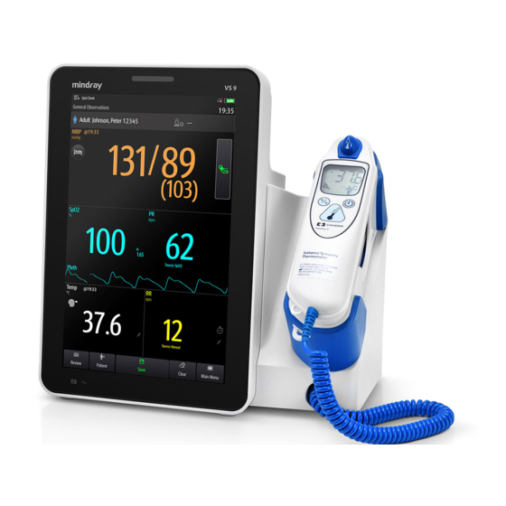
Mindray SmarTemp™ module ■ Exergen TemporalScanner™ thermometer Below is a view of monitors configured with the above modules: SmarTemp™ TemporalScanner™ Probe well Connector for thermometers or Temp sensors Temp Display Temp unit VS 9 Vital Signs Monitor Operator’s Manual 8 - 1... -
Page 82: Monitoring Temp With Smartemp™ Module
In the rectal mode, incorrect probe placement may result in bowel perforation. • Wash hands after temperature is taken. This will significantly reduce the risk of cross contamination and nosocomial contamination. VS 9 Vital Signs Monitor Operator’s Manual 8 - 2... -
Page 83: Measuring Temp
Oral. You can change the site in Temp area. For neonatal patients, when oral/axillary probe is used, the measurement site will automatically be set to Axillary. The measurement site cannot be changed. VS 9 Vital Signs Monitor Operator’s Manual 8 - 3... - Page 84 Neither measurement is taken nor is the probe replaced in the probe well in 60 seconds after the probe is withdrawn from the well. The temperature type automatically changes to Predictive mode when the probe returns to the probe well. VS 9 Vital Signs Monitor Operator’s Manual 8 - 4...
-
Page 85: Disinfecting Temperature Probe
Disinfect the probe with a soft cloth dampened with the recommended disinfectant. Wipe off all the remaining disinfectants from the probe with a soft cloth dampen with water. Dry the probe in a cool place. VS 9 Vital Signs Monitor Operator’s Manual 8 - 5... -
Page 86: Monitoring Temp With Exergen Temporalscanner™ Thermometer
There are no parts that you can service yourself except for the battery, which you should replace when low by following the instructions in this manual. For service, repair, or adjustments, return your thermometer to Mindray. • No modification of this equipment is allowed. -
Page 87: Taking A Temperature With The Temporalscanner
Place probe flush on center of forehead and depress button. Keeping button depressed, slowly slide probe mid-line across forehead to the hair line. Release button remove from head and read measurement. NOTE VS 9 Vital Signs Monitor Operator’s Manual 8 - 7... -
Page 88: Understanding The Temporalscanner™ Thermometer Led Display
TemporalScanner™ is in use, and the associated indications: Condition Display Solution/Range High Target >110 °F(43 °C) Low Target <61 °F(16 °C) High Ambient HI A >104 °F (40 °C) Low Ambient LO A <60 °F (16 °C) VS 9 Vital Signs Monitor Operator’s Manual 8 - 8... -
Page 89: Fahrenheit Or Celsius Conversion
Bend one leg of a paper clip and insert it into the pinhole in the side of the plastic housing. Push to release the battery cover, and then remove the battery. Replace the battery into the compartment. Reinstall the battery cover. VS 9 Vital Signs Monitor Operator’s Manual 8 - 9... -
Page 90: Troubleshooting
When cleaning or disinfecting the product, avoid pouring any liquid on the thermometer. You should clean the product as per your hospital’s regulations after each use. Sterilization is not allowed for the product. ■ Cleaning the case VS 9 Vital Signs Monitor Operator’s Manual 8 - 10... -
Page 91: Manually Inputting Temp
You can manually input a Temp value and save the data for future reference. Follow this procedure: Select in the Temp area. For monitors configured with Mindray SmarTemp™ module, to input Temp value in Continuous Monitoring mode, press and hold in the Temp area. - Page 92 This page intentionally left blank. VS 9 Vital Signs Monitor Operator’s Manual 8 - 12...
-
Page 93: Measuring Noninvasive Blood Pressure (Nibp)
American National Standard: manual, electronic, or automated sphygmomanometers. • NIBP measurement can be performed during electro-surgery and discharge of a defibrillator. VS 9 Vital Signs Monitor Operator’s Manual 9 - 1... -
Page 94: Nibp Safety Information
Never connect intra-arterial or intra-venous lines, or any other incompatible connectors to the NIBP hose. This can cause serious injury or death. • NIBP diagnostic significance must be decided by the hospital’s clinician staff. VS 9 Vital Signs Monitor Operator’s Manual 9 - 2... -
Page 95: Nibp Measurement Limitations
In Continuous Monitoring mode, there are four NIBP measurement modes: ■ Manual: measurement on demand. ■ Auto: repeated measurement at set interval or an interval synchronized with the real time clock. VS 9 Vital Signs Monitor Operator’s Manual 9 - 3... -
Page 96: Nibp Display
Mean pressure (displayed after the measurement completes) or cuff pressure (displayed during the measurement) Diastolic pressure Start/Stop NIBP measurement Below is an example of NIBP screen in Continuous Monitoring mode: (12) (11) (10) VS 9 Vital Signs Monitor Operator’s Manual 9 - 4... -
Page 97: Preparing For Nibp Measurement
■ Comfortably seated ■ Legs uncrossed ■ Feet flat on the floor ■ Back, arm and feet supported For patients taking orthostatic BP measurement, refer to 9.10 Orthostatic BP Measurement. VS 9 Vital Signs Monitor Operator’s Manual 9 - 5... -
Page 98: Placing The Nibp Cuff
Middle of the cuff should be at the level of the right atrium of the heart. If it is not, use the measurement correction formula to correct the measurement. For more information, see 9.8.9 Correcting the NIBP Measurements. VS 9 Vital Signs Monitor Operator’s Manual 9 - 6... -
Page 99: Performing Measurement
Below is an example of NIBP screen if Measurements is set to Twice: The last measurement time NIBP unit: mmHg or kPa Patient position and site of the first measurement Patient position and site of the second measurement VS 9 Vital Signs Monitor Operator’s Manual 9 - 7... -
Page 100: Performing Auto Measurement
Prepare the patient and place the cuff as instructed in 9.6 Preparing for NIBP Measurement. Select a workflow under Continuous Monitoring. Select to set the patient position and measurement site. Select the NIBP numeric area to enter the NIBP dialog. Select STAT. VS 9 Vital Signs Monitor Operator’s Manual 9 - 8... -
Page 101: Performing Sequence Measurement
Start mode defines how NIBP auto mode works. In Continuous Monitoring mode, you can set the start mode. Follow this procedure: Select the NIBP numeric area to enter the NIBP dialog. Set Start Mode. VS 9 Vital Signs Monitor Operator’s Manual 9 - 9... -
Page 102: Enabling The Nibp End Tone
In Continuous Monitoring mode, select the NIBP numeric area to enter the NIBP dialog. In Spot Check mode, select the Main Menu quick key → from the Parameters column select Setup → select NIBP. Select the Setup tab. Set Display Format. VS 9 Vital Signs Monitor Operator’s Manual 9 - 10... -
Page 103: Setting The Nibp Alarm Limits Display Switch
Workflow → input the required password → select Select on the right of the workflow to be set. Make sure the workflow is under Spot Check. Select Parameters Setup → the NIBP tab. VS 9 Vital Signs Monitor Operator’s Manual 9 - 11... -
Page 104: Bp Averaging Display
BP measurement (see 9.9.4.2 Setting the Number of Measurement) at the set interval (see 9.9.4.3 Setting Time between Readings). At the completion of automatic measurement, select Return to check the readings of each measurement and the averaged BP values. VS 9 Vital Signs Monitor Operator’s Manual 9 - 12... -
Page 105: Changing Bp Averaging Settings
Select the Main Menu quick key → from the Configuration column select Workflow → input the required password → select Select on the right of the workflow to be set. Make sure the workflow is under Spot Check. VS 9 Vital Signs Monitor Operator’s Manual 9 - 13... -
Page 106: Orthostatic Bp Measurement
Lying blood pressure: displayed in the form of Sys/Dia (Mean) Standing blood pressure: displayed in the form of Sys/Dia (Mean). The lowest values measured are used in contrasting. Differences between the lying blood pressure and lowest standing blood pressure VS 9 Vital Signs Monitor Operator’s Manual 9 - 14... -
Page 107: Performing Orthostatic Bp Measurement
Make sure the workflow is under Spot Check. Select Parameters Setup → the NIBP tab. Under Orthostatic BP Measurement, set Lying Duration. VS 9 Vital Signs Monitor Operator’s Manual 9 - 15... - Page 108 Follow this procedure: In Spot Check mode, select the Main Menu quick key → from the System column select Maintenance → input the required password → select → Module. VS 9 Vital Signs Monitor Operator’s Manual 9 - 16...
-
Page 109: Assisting Venous Puncture
Cannot see NIBP Check that the NIBP is set to display in the Edit Workflow menu. numeric area on the For more information, see 3.9.1.2 Setting the Screen Layout. main screen VS 9 Vital Signs Monitor Operator’s Manual 9 - 17... - Page 110 This page intentionally left blank. VS 9 Vital Signs Monitor Operator’s Manual 9 - 18...
-
Page 111: Monitoring Carbon Dioxide (Co )
Continuous Monitoring mode. 10.2 Safety WARNING • Route all tubing away from the patient’s throat to avoid strangulation. VS 9 Vital Signs Monitor Operator’s Manual 10 - 1... -
Page 112: Measurement Limitations
Measurement accuracy is unspecified for breath rate larger than 60 bpm. 10.4 Display The CO numeric and waveform areas provide FiCO measurement, EtCO measurement, RR measurement and a CO waveform. VS 9 Vital Signs Monitor Operator’s Manual 10 - 2... -
Page 113: Measuring Co
To measure CO , follow this procedure: Select an appropriate sample line according to the patient category. Connect the sample line to the CO adapter that is installed on the monitor. VS 9 Vital Signs Monitor Operator’s Manual 10 - 3... - Page 114 NOTE • When sample gas of 37 °C, sample flowrate of 50 ml/min, room temperature of 23 °C, 100% RH, the sample line with a general type should be replaced VS 9 Vital Signs Monitor Operator’s Manual 10 - 4...
-
Page 115: Automatic Co
Changing Alarm settings. Set alarm properties as desired. 10.7.2 Setting the CO Waveform In Continuous Monitoring mode, you can set the CO waveform. To do so, follow this procedure: VS 9 Vital Signs Monitor Operator’s Manual 10 - 5... -
Page 116: Entering The Standby Mode
Set the humidity compensation on or off according to the actual condition. To set the humidity compensation, follow this procedure: Select the CO numeric area or waveform area to enter the CO2 dialog. Select the Setup tab. VS 9 Vital Signs Monitor Operator’s Manual 10 - 6... -
Page 117: Setting Gas Compensation
10ml/min or greater, it indicates that the module leaks. Perform the leakage test again. If the problem remains, contact your service personnel for help. 10.8.1 Automatic Barometric Pressure The CO module has the function of automatic barometric pressure compensation. VS 9 Vital Signs Monitor Operator’s Manual 10 - 7... -
Page 118: Calibrating The Co
Messages. Problem Solution EtCO measurements Check the patient status. too low Check the sample line and connectors for leakage. Ventilate the room if the environmental CO concentration is too high. VS 9 Vital Signs Monitor Operator’s Manual 10 - 8... -
Page 119: Monitoring Respiration
Respiration monitoring is not for use on the patients who are very active, as this will cause false alarms. 11.2 RR Display The RR parameter area displays its source. ■ Sourcing from CO2: VS 9 Vital Signs Monitor Operator’s Manual 11 - 1... -
Page 120: Manually Inputting Rr Value
Resp area. A 60s timer is displayed and starts counting seconds. Count the total number of Resp of the patient in the past minute. Input the number and select Select the Save quick key to save the data. VS 9 Vital Signs Monitor Operator’s Manual 11 - 2... -
Page 121: Changing The Rr Settings
Workflow → input the required password → select Select on the right of the workflow to be set. Select Parameters Setup → RR tab. Set Timer Reminder Interval as needed. VS 9 Vital Signs Monitor Operator’s Manual 11 - 3... - Page 122 This page intentionally left blank. VS 9 Vital Signs Monitor Operator’s Manual 11 - 4...
-
Page 123: Manual Parameters
You can also add new types of parameters to the list. For details, refer to 17.8.6 Adding a New Manual Parameter. 12.2 The Manual Input Display The following figure shows the manual input area. Your display may be configured to look different. VS 9 Vital Signs Monitor Operator’s Manual 12 - 1... -
Page 124: Inputting/Editing Parameter Information
Room Air, Aerosol Mask, Bi PAP, C PAP, Face Mask, Mask, Bnasal Cannula, Nonrebreather, Partial Rebreather, T-piece, Trach Collar, Ventilator, Venturi Mask, Oxymizer LOC (ACVPU) Alert, Confusion, Reacting to voice, Reacting to pain, Unresponsive Supp. O Yes, No VS 9 Vital Signs Monitor Operator’s Manual 12 - 2... -
Page 125: Changing The Display Of Manual Parameters
Select Parameters Setup → Manual Input tab. Then select an item and from the popup list, select the parameter to be displayed. Return to the main screen and switch workflows for the setting to take effect. VS 9 Vital Signs Monitor Operator’s Manual 12 - 3... - Page 126 This page intentionally left blank. VS 9 Vital Signs Monitor Operator’s Manual 12 - 4...
-
Page 127: Clinical Assistive Applications (Caa)
MEWS, NEWS and NEWS2 are intended for adult patients only. The patient category applied to the Custom Score is defined by Mindray Clinical Score Configuration Tool. For more information, see Mindray Clinical Scoring Config Tool Instruction for Use (P/N: 046- 012986-00). -
Page 128: The Ews Display
Select the Main Menu quick key → from the CAA column select EWS. ■ Take NEWS2 as an example, the EWS screen is shown as follows. Your screen may be slightly different due to the configuration. VS 9 Vital Signs Monitor Operator’s Manual 13 - 2... - Page 129 Keyboard symbol: indicates that the value is manually entered. Select this button to see the clinical response to the current score. Scoring interval Scoring countdown: time to the next scoring. EWS protocol label (10) The scoring time VS 9 Vital Signs Monitor Operator’s Manual 13 - 3...
-
Page 130: Performing Ews Scoring
NIBP measurement. ◆ Alarm: the monitor automatically starts scoring when an alarm occurs to the parameter for scoring. ◆ If no option is selected, the monitor does not initiate auto scoring. VS 9 Vital Signs Monitor Operator’s Manual 13 - 4... -
Page 131: Setting Auto Scoring Interval
The score of auto obtained parameter reaches 3, or falls from 3 to a lower score. To enable the auto refreshing score function, follow this procedure: From the EWS page select Setup. VS 9 Vital Signs Monitor Operator’s Manual 13 - 5... -
Page 132: Changing Ews Settings
Select the Review quick key → select Scoring Review tab. Select PID and from the popup list select the ID of which the scores are to be viewed. Select Filter and choose a protocol if needed. VS 9 Vital Signs Monitor Operator’s Manual 13 - 6... -
Page 133: Glasgow Coma Scale (Gcs)
• The monitor provides MEWS, NEWS, and NEWS2 by default. You cannot delete them. • For details about how to import scoring tools, refer to Mindray Clinical Scoring Config Tool Instruction for Use (P/N: 046-012986-00). 13.2 Glasgow Coma Scale (GCS) The Glasgow Coma Scale (GCS) function is based on Teasdale’s Assessment of Coma and... -
Page 134: Gcs Display
Your display may look slightly different. If GCS is not displayed, you can follow the procedure in 12.4 Changing the Display of Manual Parameters to add GCS to the list. VS 9 Vital Signs Monitor Operator’s Manual 13 - 8... -
Page 135: Accessing The Gcs Dialog
Performing GCS Scoring To perform scoring, follow this procedure: From the Eye Opening area, Verbal Response area, and Motor Response area, respectively select an item that represents the patient’s status. VS 9 Vital Signs Monitor Operator’s Manual 13 - 9... -
Page 136: Reviewing Gcs Data
You can also add custom pain scores to the list. For details, refer to 17.8.7.2 Adding a Custom Pain Scale. Pain Score is applicable for adult, pediatric, and neonatal patients. VS 9 Vital Signs Monitor Operator’s Manual 13 - 10... -
Page 137: The Pain Score Display
PI, PR, NIBP, and Temp. The measurements of these parameters displays in big numerics. 13.4.1 Entering the Targeted Goal Screen To enter the Targeted Goal screen, in Continuous Monitoring mode, select Targeted Goal quick key. VS 9 Vital Signs Monitor Operator’s Manual 13 - 11... -
Page 138: The Display Of The Targeted Goal Screen
Select the target parameter statistics area to enter the parameter statistics setup menu. Set the range of each section and the target section. ■ Select the desired waveform area, parameter numeric area, or dashboard to enter corresponding parameter setup menu. VS 9 Vital Signs Monitor Operator’s Manual 13 - 12... - Page 139 13.4.3.3 Selecting the SpO Statistics Length The Duration of SpO statistics is configurable. From the SpO statistics area, select the duration to redefine the length of SpO statistics. VS 9 Vital Signs Monitor Operator’s Manual 13 - 13...
- Page 140 This page intentionally left blank. VS 9 Vital Signs Monitor Operator’s Manual 13 - 14...
-
Page 141: Recording
Latch: pull it away from the recorder to open the recorder door. 14.2 Starting Recordings Recordings can be started manually. In Continuous Monitoring mode, to start a recording, you can either: ■ Press the hardkey on the front of the recorder. VS 9 Vital Signs Monitor Operator’s Manual 14 - 1... -
Page 142: Stopping Recordings
Waveform 2 in turn. The recorder can record up to 2 waveforms at a time. Select Recording Duration to set the duration of real-time recording. Select Recorder Paper Speed to set the speed for recording waveforms. VS 9 Vital Signs Monitor Operator’s Manual 14 - 2... -
Page 143: Clearing Recording Tasks
Removing Paper Jam If the recorder works incorrectly or produces unusual sounds, check if there is a paper jam. If a paper jam is detected, follow this procedure to remove it: VS 9 Vital Signs Monitor Operator’s Manual 14 - 3... -
Page 144: List Of Recording Reports
■ Realtime reports ◆ Realtime Segment Waveform Record (Continuous Monitoring) ■ History reports ◆ Spotcheck Record ◆ EWS Record ◆ Event Detail ◆ Tabular Trend Report ◆ Graphic Trend Report VS 9 Vital Signs Monitor Operator’s Manual 14 - 4... -
Page 145: Review
To enter the review dialog, select the Review quick key. 15.2.2 Example Review Dialog The review dialogs have similar structure. The graphic trends review dialog is taken as an example: (12) (11) (10) VS 9 Vital Signs Monitor Operator’s Manual 15 - 1... -
Page 146: Reviewing The Tabular Trends
Set Filter to a period of time (30 seconds to 3 hours selectable), a parameter (Temp, Scoring etc.) or type of data (Manually Saved for example). Select a record to be viewed and select Detail to check more information. VS 9 Vital Signs Monitor Operator’s Manual 15 - 2... -
Page 147: Reviewing Scores
5.3.3 Alarm Indicators. Different color blocks are displayed on the left of each event to indicate different event types. ■ Red: high priority alarm event VS 9 Vital Signs Monitor Operator’s Manual 15 - 3... - Page 148 On the Detail page, you can also view the details of other events by either: ■ Selecting and then the desired event. ■ Selecting to view the previous or next event. VS 9 Vital Signs Monitor Operator’s Manual 15 - 4...
-
Page 149: Managing Configurations
Select the Main Menu quick key → from the Configuration column select Manage → input the required password → select Select Department Type. Select a department. Select OK. VS 9 Vital Signs Monitor Operator’s Manual 16 - 1... -
Page 150: Setting Default Patient Category
Select the Main Menu quick key → from the Configuration column select Manage → input the required password → select Select Import Configuration. Select the workflows and User Maintenance Settings to import. Select Import. VS 9 Vital Signs Monitor Operator’s Manual 16 - 2... -
Page 151: Modifying Configuration Password
30 minutes, the monitor behaves the same as it is normally turned off. VS 9 Vital Signs Monitor Operator’s Manual 16 - 3... - Page 152 This page intentionally left blank. VS 9 Vital Signs Monitor Operator’s Manual 16 - 4...
-
Page 153: Password-Protected User Settings
If the monitor is connected to the wired network, the monitor can automatically set the patient’s bed number according to the bed number information bonded to the bedside network connector. To enable this function, follow this procedure: VS 9 Vital Signs Monitor Operator’s Manual 17 - 1... -
Page 154: Changing Patient Management Settings
Select the Main Menu quick key → from the System column select Maintenance → input the required password → select Select the Patient Management tab → ADT Query tab. Select the query criteria as desired. VS 9 Vital Signs Monitor Operator’s Manual 17 - 2... -
Page 155: Auto Discharging A Patient After Monitor Power Off
Select the Patient Management tab → Discharge tab. Select Clear All Patient Data. Select OK. Select OK again for confirmation until a message indicating you that all data is cleared. VS 9 Vital Signs Monitor Operator’s Manual 17 - 3... -
Page 156: Setting Patient Location Options For The Standby Screen
→ input the required password → select Select the Authorization Setup tab → Authorization Setup tab. From the Maintenance area, set User Maintenance to select the password for accessing the monitor’s Maintenance dialog. VS 9 Vital Signs Monitor Operator’s Manual 17 - 4... -
Page 157: Selecting Password For Changing Alarm Settings
◆ No Password: no password is required for viewing discharged patient data. ◆ Clinician Login: discharged patient data can be viewed only after clinician login succeeds. VS 9 Vital Signs Monitor Operator’s Manual 17 - 5... -
Page 158: Changing Settings About Saving And Sending Data
Switch on Record After Saving. 17.4.1.5 Enabling Automatic Logout after Saving Data You can set the monitor to automatically log out of the clinician account after saving data. do so, follow this procedure: VS 9 Vital Signs Monitor Operator’s Manual 17 - 6... -
Page 159: Setting Items About Sending Data
To do so, follow this procedure: Select the Main Menu quick key → from the System column select Maintenance → input the required password → select Select the Save&Send tab. Switch on Clinician Match Required. VS 9 Vital Signs Monitor Operator’s Manual 17 - 7... -
Page 160: Changing The Alarm Settings
Set High Alarm Interval, Med Alarm Interval, and Low Alarm Interval. Item Range Default High Alarm Interval 3 s to 15 s 10 s Med Alarm Interval 3 s to 30 s 20 s VS 9 Vital Signs Monitor Operator’s Manual 17 - 8... -
Page 161: Setting Alarm Pausing And Resetting Properties
17.5.2.2 Setting the Alarm Pause Time/Alarm Tone Pause Time The alarm pause time or alarm tone pause time can be set to 1 min, 2 min, 3 min, or Permanent. The default audio pause time is two minutes. VS 9 Vital Signs Monitor Operator’s Manual 17 - 9... - Page 162 ◆ Off When Reset: when the alarm system is reset, both the alarm tone and alarm lamp of the current alarms are switched off. VS 9 Vital Signs Monitor Operator’s Manual 17 - 10...
-
Page 163: Latching Physiological Alarms
Select the Alarm tab → Nurse Call tab. Select Signal Type. ◆ Pulse: the nurse call signal is a pulse signal and each pulse lasts one second. When multiple alarms simultaneously occur, only one pulse signal is VS 9 Vital Signs Monitor Operator’s Manual 17 - 11... -
Page 164: Changing Alarm Priority Settings
17.5.5.4 Setting the Switch of the SpO Desat Alarm Off You can choose whether switching off the SpO Desat alarm is permissible or not. To do so, follow this procedure: VS 9 Vital Signs Monitor Operator’s Manual 17 - 12... -
Page 165: Setting The Alarm Delay Time
To set the alarm delay time, follow this procedure: Select the Main Menu quick key → from the System column select Maintenance → input the required password → select VS 9 Vital Signs Monitor Operator’s Manual 17 - 13... -
Page 166: Changing The Standby Settings
Enabling Black Standby Screen The monitor provides a black screen function for standby mode. If enabled, the screen turns black after the monitor enters standby mode. To do so, follow this procedure: VS 9 Vital Signs Monitor Operator’s Manual 17 - 14... -
Page 167: Changing Caa Settings
Select the Main Menu quick key → from the System column select Maintenance → input the required password → select Select the CAA tab → GCS tab. Set high limit, low limit and color for each level. VS 9 Vital Signs Monitor Operator’s Manual 17 - 15... -
Page 168: Changing Module Settings
Manually Zeroing the CO Module To zero the CO module, follow this procedure: Select the Main Menu quick key → from the System column select Maintenance → input the required password → select VS 9 Vital Signs Monitor Operator’s Manual 17 - 16... -
Page 169: Hiding The Invalid Display After Zeroing The Co Module
→ input the required password → select Select Module → Manual Input tab, and then select Add. Select Name and input the name of the new parameter with the on-screen key- board. VS 9 Vital Signs Monitor Operator’s Manual 17 - 17... -
Page 170: Managing Pain Score
Select Name and input the name of the description with the on-screen keyboard. Set Type to Numeric or Text. ◆ The type of a description cannot be changed after saving. VS 9 Vital Signs Monitor Operator’s Manual 17 - 18... -
Page 171: Setting Parameter Measurement Timeout
Below is a list of the units you can set: Parameter Options Default Height Unit cm, inch Weight Unit kg, lb Glucose Unit mg/dl, mmol/L mg/dl I/O Fluid Unit ml, L VS 9 Vital Signs Monitor Operator’s Manual 17 - 19... -
Page 172: 17.10 Setting The Time
To set the time synchronization interval, follow this procedure: Select the Main Menu quick key → from the System column select Maintenance → input the required password → select Select the Time tab→ Time Synchronization tab. Set Interval. VS 9 Vital Signs Monitor Operator’s Manual 17 - 20... -
Page 173: 17.10.2 Enabling Auto Daylight Savings Time
Select the Main Menu quick key → from the System column select Maintenance → input the required password → select Select the Scanner tab. The Scanner Info. tab is displayed. Set Data Parse Mode and then set other information as instructed below: VS 9 Vital Signs Monitor Operator’s Manual 17 - 21... -
Page 174: Identifying The Barcode Reader (For The Non-Mindray Custom 2D Barcode Reader)
◆ If you select DLL, continue to set the Data Encoding Type. 17.13.2 Identifying the Barcode Reader (for the non-Mindray Custom 2D Barcode Reader) When you are using barcode readers other than the JADAK Flexpoint HS-1R, HS-1RS or HS-1M, you should select the barcode reader from the USB device list, so that the monitor can identify the barcode reader. -
Page 175: 17.15 Configuring The Network
17.15.1 Network Safety Information CAUTION • Wireless network designing, deploying, debugging, and maintenance should be executed by Mindray service personnel or authorized technicians. • Always set the wireless network according to local wireless regulations. • Using 5GHz frequency band is recommended whenever possible. There are more interference sources in 2.4GHz frequency band. -
Page 176: 17.15.2 Selecting A Network Type
Network disconnection does not have an impact on local monitoring functions. • Contact Mindray service personnel if cybersecurity problems occur. 17.15.2 Selecting a Network Type To select network type, follow this procedure: Select the Main Menu quick key → from the System column select Maintenance →... -
Page 177: 17.15.4 Setting The Wireless Network
From the USB Drive tab, select certifications you want to import from the USB memory device, and then select Import. 17.15.6 Enabling Selecting a CMS To enable selecting a CMS, follow this procedure: VS 9 Vital Signs Monitor Operator’s Manual 17 - 25... -
Page 178: 17.15.7 Adding Cmss
Select the Main Menu quick key → from the System column select Maintenance → input the required password → select Select the Network Setup tab → Transfer Setup tab. Set Send Data to HL7. VS 9 Vital Signs Monitor Operator’s Manual 17 - 26... -
Page 179: Setting Multicast Parameters
To access the MLDAP server, set your monitor as follows: Select the Main Menu quick key → from the System column select Maintenance → input the required password → select VS 9 Vital Signs Monitor Operator’s Manual 17 - 27... -
Page 180: Testing Mldap Server Connection
17.17 Defining Other Functions 17.17.1 Setting the SpO Tone Mode The monitor adjusts the QRS tone (pitch tone) according to the SpO values. To set the tone mode, follow this procedure: VS 9 Vital Signs Monitor Operator’s Manual 17 - 28... -
Page 181: 17.17.2 Selecting The Language
Select the Main Menu quick key → from the System column select Maintenance → input the required password → select Select the Other tab. Select Browse System Log → OK to enter the System Log page. VS 9 Vital Signs Monitor Operator’s Manual 17 - 29... -
Page 182: 17.17.4 Exporting System Log
Connect a USB drive to the monitor’s USB port. Select the Main Menu quick key → from the System column select Maintenance → input the required password → select Select the Other tab. Select Export Patient Data. VS 9 Vital Signs Monitor Operator’s Manual 17 - 30... -
Page 183: Battery
• Keep batteries out of the reach of children. • Use only Mindray specified batteries. Use of a different battery may present a risk of fire or explosion. • Keep the batteries in their original package until you are ready to use them. -
Page 184: Battery Indications
When a battery is charged on a new monitor for the first time, the estimated run time will not be displayed. Instead, a percentage indicating the current charge is displayed on the right of the battery symbol. VS 9 Vital Signs Monitor Operator’s Manual 18 - 2... -
Page 185: Battery-Related Alarms
Take out the old battery. Then insert the new battery into the battery compart- ment with the battery terminal inwards. Turn the latch back to the middle and close the battery door. VS 9 Vital Signs Monitor Operator’s Manual 18 - 3... -
Page 186: Connecting An External Battery
Disconnect the monitor from the patient and stop all monitoring and measuring procedures. Turn off the monitor. Install the battery to be conditioned. Connect the monitor to AC power. Allow the battery to be charged uninterruptedly till it is fully charged. VS 9 Vital Signs Monitor Operator’s Manual 18 - 4... -
Page 187: Checking Battery Performance
Remove the battery from the equipment if the equipment is not used for a prolonged time (for example, several weeks). Otherwise the battery may overdischarge. • Storing batteries at high temperature for an extended period of time will significantly shorten their life expectancy. VS 9 Vital Signs Monitor Operator’s Manual 18 - 5... -
Page 188: Recycling Batteries
Properly dispose of batteries according to local regulations. WARNING • Do not open batteries, heat batteries above 60 °C, incinerate batteries, or short the battery terminals. They may ignite, explode, leak or heat up, causing personal injury. VS 9 Vital Signs Monitor Operator’s Manual 18 - 6... -
Page 189: Care And Cleaning
Do not attempt to clean the device while monitoring a patient. CAUTION • If you spill liquid on the equipment or accessories, contact Mindray or your service personnel. • Avoid wetting the pins and metal parts of the equipment, mounting kits or accessories during cleaning and disinfection. -
Page 190: Cleaning And Disinfecting The Equipment
1-Propanol Liquid 1-Propanol 50% Metrex CaviCide1™ Liquid Diisobutylphenoxyethoxyethyl dimethyl benzyl ammonium chloride 0.28%, Isopropanol 17.2% Virex® II 256 (1:256) Liquid Didecyl dimethyl ammonium chloride 8.704%, n-Alkydimethyl benzyl ammonium chloride 8.190% VS 9 Vital Signs Monitor Operator’s Manual 19 - 2... - Page 191 Germicidal Disposable chlorides 0.07%, n-Alkyl dimethyl benzyl Wipe ammonium chlorides 0.07% PDI Sani-Cloth® Plus Wipes n-Alkyl dimethyl ethylbenzyl ammonium Germicidal Disposable chlorides 0.125%, n-Alky dimethyl benzyl Cloth ammonium chlorides 0.125% VS 9 Vital Signs Monitor Operator’s Manual 19 - 3...
-
Page 192: Cleaning The Equipment
19.4 Disinfecting the Equipment Disinfect the monitor as required in your hospital’s servicing schedule using the disinfecting agents listed in the table above. Cleaning the monitor before disinfecting is recommended. VS 9 Vital Signs Monitor Operator’s Manual 19 - 4... -
Page 193: Cleaning The Thermal Print Head
Never clean or disinfect the metalic connectors at either end of the accessories. • Use only Mindray approved cleaners and disinfectants and methods listed in this section to clean or disinfect the accessories. Warranty does not cover damage caused by unapproved substances or methods. -
Page 194: Approved Accessories Cleaning And Disinfecting Agents
Germicidal 0.14%, Disposable Wipe n-Alkyl dimethyl benzyl ammonium chlorides 0.14% PDI Sani-Cloth® Plus Wipes n-Alkyl dimethyl ethylbenzyl ammonium chlorides Germicidal 0.125%, Disposable Wipe n-Alky dimethyl benzyl ammonium chlorides 0.125% VS 9 Vital Signs Monitor Operator’s Manual 19 - 6... - Page 195 Clorox Dispatch® Hospital Wipes Sodium Hypochlorite 0.65% Cleaner Disinfectant Towels with Bleach Clorox Healthcare® Bleach Wipes Sodium Hypochlorite 0.55% Germicidal Wipes Clorox Healthcare® Wipes Hydrogen Peroxide 1.4% Hydrogen Peroxide Cleaner Disinfectant Wipes VS 9 Vital Signs Monitor Operator’s Manual 19 - 7...
-
Page 196: Cleaning The Accessories
19.7 Sterilization Sterilization is not recommended for this monitor, related products, accessories, or supplies unless otherwise indicated in the Instructions for Use that accompany the products, accessories or supplies. VS 9 Vital Signs Monitor Operator’s Manual 19 - 8... -
Page 197: Maintenance
No modification of this equipment is allowed. • This equipment contains no user serviceable parts. • Software upgrades to the monitor can only be done by Mindray service engineers with Mindray upgrading tools. • Do not open the equipment housings. All servicing and future upgrades must be carried out by the service personnel. -
Page 198: Maintenance And Testing Schedule
2. Follow any repairs or replacement of relevant module. 3. Once a year for CO tests. 4. Once every two years for other parameter module performance tests. VS 9 Vital Signs Monitor Operator’s Manual 20 - 2... -
Page 199: Checking Version Information
Visually inspect the equipment before its first used every day. If you find any signs of damage, remove the monitor from use and contact the service personnel. Verify that the equipment meets the following requirements: VS 9 Vital Signs Monitor Operator’s Manual 20 - 3... -
Page 200: Performing Power-On Test
20.6.2 NIBP Accuracy Test The NIBP accuracy test should be performed once every two years or when you doubt the NIBP measurements. The NIBP accuracy test should be performed by Mindray- qualified service personnel only. 20.7 Disposing of the Monitor Dispose of the monitor and its accessories when its service life is reached. - Page 201 WARNING • For disposal of parts and accessories, where not otherwise specified, follow local regulations regarding disposal of hospital waste. VS 9 Vital Signs Monitor Operator’s Manual 20 - 5...
- Page 202 This page intentionally left blank. VS 9 Vital Signs Monitor Operator’s Manual 20 - 6...
-
Page 203: Accessories
18 mW. The information about the wavelength range and maximum photic output consumption can be especially useful to clinicians, for example, when photodynamic therapy is performed. VS 9 Vital Signs Monitor Operator’s Manual 21 - 1... -
Page 204: Extension Cables And Adapter Cables Available For Purchase
4001 040-003383-00 Disposable Pediatric sensor, RD SET (10 to 50 PDT, adhesive, finger or 4002 040-003384-00 Disposable Infant (3 to sensor, RD Set, 20 kg) adhesive, thumb or great toe VS 9 Vital Signs Monitor Operator’s Manual 21 - 2... -
Page 205: Masimo Spo Lncs Sensors Also Compatible
(<3 kg or > foot (for neonate), finger 40 kg) or toe (for adult) LNCS Inf 0600-00-0158 Disposable Infant (3-20 sensor, 20 pcs/ box, adhesive, thumb or great toe VS 9 Vital Signs Monitor Operator’s Manual 21 - 3... -
Page 206: Nellcor Spo
(for adult) or foot (for neonate) 21.2 NIBP Accessories 21.2.1 NIBP Hoses Available for Purchase Applicable Model Part No. Description Usage patient CM1903 6200-30-09688 NIBP Hose, Inbuilt Reusable Adult/ connector(3m) Pediatric/ Neonate VS 9 Vital Signs Monitor Operator’s Manual 21 - 4... -
Page 207: Cuffs Available For Purchase
Cuff, 7.1-13.1 cm, pkg of 20 Disposable Neonate CM1500E 125-000055-00 Cuff, 5#, 8-15 cm, pkg of 20 Disposable Neonate 115-031807-00 Cuff starter kit, bladderless Reusable Child/Small adult/ Adult/ Adult thigh VS 9 Vital Signs Monitor Operator’s Manual 21 - 5... -
Page 208: Temp Accessories
2000 (100 boxes, neonate 20 pcs/box) 21.3.4 Exergen Temp Probe Available for Purchase Applicable Model Part No. Description Usage patient 124237-AF-MR 040-003273-00 TAT-5000S Temporal Reusable Adult, pediatric, Scanner neonate VS 9 Vital Signs Monitor Operator’s Manual 21 - 6... -
Page 209: Co Accessories
Ped Oral‐Nasal CO2 FilterLine w/O2 0010-10-42570 Disposable Adult MVAOL Adt Oral-Nasal CO2 FilterLine w/O2 L 0010-10-42571 Disposable Pediatric MVPOL Ped Oral‐Nasal CO2 FilterLine w/O2 L 0010-10-42572 Disposable Adult MVANH Adult Nasal CO2 FilterLine VS 9 Vital Signs Monitor Operator’s Manual 21 - 7... -
Page 210: Mount And Mounting Accessories
045-003427-00 Wall Mount Bracket 115-025386-00 Wall Mount for Kaiser - 6" 045-003424-00 Quick Release Tray 115-020575-00 Bedrail Clamp 21.6 Miscellaneous Accessories Description DA8K-10-14452 U.S. Power Cord 0012-25-0001 U.S. Power Cord VS 9 Vital Signs Monitor Operator’s Manual 21 - 8... - Page 211 Welch Allyn SureTemp Plus Thermometer Module 0992-00-0213-02 Welch Allyn SureTemp Plus Oral Probe 040-002471-00 SURETEMP probe cover, WELCH ALLYN, QTY 7500 115-034132-00 Li-ion Battery (10.8V, 5600mA, LI23I003A, VS 9) 115-008393-00 Barcode scanner kit (1D) 115-039575-00 2D Barcode reader, HS-1M, JADAK 115-039635-00...
- Page 212 This page intentionally left blank. VS 9 Vital Signs Monitor Operator’s Manual 21 - 10...
-
Page 213: A Product Specifications
• When the monitor and related products have differing environmental specifications, the effective range for the combined products is that range which is common to the specifications for all products. VS 9 Vital Signs Monitor Operator’s Manual A - 1... -
Page 214: Power Supply Specifications
–20ºC to 50 ºC (-4°F to 104°F) 122°F) Relative humidity (non-condensing) up to 95% up to 95% Power Supply Specifications AC Power Line voltage 100 to 240 VAC (±10%) Current 0.9 to 0.5 A VS 9 Vital Signs Monitor Operator’s Manual A - 2... -
Page 215: Physical Specifications
≤ 275mmx 185mm x 135mm Weight ≤3.4 kg (with Masimo SpO module, NIBP module, recorder module and a battery; without accessory) Hardware Specifications A.5.1 Display Screen type Capacitive touch screen VS 9 Vital Signs Monitor Operator’s Manual A - 3... -
Page 216: Recorder
Wired network 1 RJ45 connector, 100 BASE-TX 2 standard connectors, USB 2.0, type A Equipotential Grounding Terminal Multi-Functions Connector 1 MINI-D RIBBON connector External battery connector A.5.6 Outputs Nurse Call Signal VS 9 Vital Signs Monitor Operator’s Manual A - 4... -
Page 217: Wireless Network
WARNING • All network functions of data communication are designed to operate on a private network. A.5.8.1 System Capacity Number of the monitors supported by a single AP: ≤ 16 VS 9 Vital Signs Monitor Operator’s Manual A - 5... - Page 218 0.2m 2.4GHz WiFi Adjacent channel 1 1.0m (2412- and 11(802.11n) 2462MHz) Co-channel 2.5m 4.0m lower adjacent band 0.2m 0.5m LTE of 10MHz upper adjacent band 0.2m 0.5m LTE of 10MHz VS 9 Vital Signs Monitor Operator’s Manual A - 6...
-
Page 219: Bluetooth Specification
Line of Sight Distance The line of sight distance between the monitor and the AP is no less than 50 meters. A.5.9 Bluetooth Specification Protocol Bluetooth 5 Modulation mode GFSK VS 9 Vital Signs Monitor Operator’s Manual A - 7... -
Page 220: A.5.10 Bluetooth Performance Specifications
(2402- lower adjacent 2480MHz) band LTE, upper adjacent band LTE Wi-Fi (802.11n) 0.2m 0.2m channel 6 0.2m 0.2m Wi-Fi (802.11n) channel 6, lower adjacent band LTE, upper adjacent band LTE VS 9 Vital Signs Monitor Operator’s Manual A - 8... -
Page 221: Measurement Specifications
Nellcor: (Desat+1) or 20 (whichever is greater) to (high limit – 2) Desat 0 to (low limit – 1) Masimo SpO Modul Standards meets the requirements of ISO 80601-2-61 Measurement 1% to 100% range PI measurement range 0.02 to 20% Resolution VS 9 Vital Signs Monitor Operator’s Manual A - 9... - Page 222 70 to 100%. This variation equals plus or minus one standard deviation. Plus or minus one standard deviation encompasses 68% of the population. Nellcor SpO Module Standards Meet standards of ISO 80601-2-61 Measurement range 0% to 100% Resolution VS 9 Vital Signs Monitor Operator’s Manual A - 10...
- Page 223 ≤ 20 s (normal perfusion, no disturbance, PR value sudden change within 25 – 220 bpm) Accuracy ±3 bpm (without motion) ±5 bpm (with motion) Low perfusion conditions Pulse amplitude: >0.02% Light penetration: >5% VS 9 Vital Signs Monitor Operator’s Manual A - 11...
-
Page 224: Nibp
1 min, 2 min, 2.5 min, 3 min, 5 min, 10 min, 15 min, 20 min, 30 min, repetition intervals 1 hour, 1.5 hours, 2 hours, 3 hours, 4 hours, 8 hours STAT mode cycle 5 min time VS 9 Vital Signs Monitor Operator’s Manual A - 12... - Page 225 Software Adult: 297±3 mmHg overpressure Pediatric: 297±3 mmHg protection Neonate: 147±3 mmHg Hardware Adult: ≤330 mmHg overpressure Pediatric: ≤330 mmHg protection Neonate: ≤165 mmHg Alarm limit Range (mmHg) Step (mmHg) VS 9 Vital Signs Monitor Operator’s Manual A - 13...
-
Page 226: Temp
Monitor mode: 25 °C to 44 °C (77 °F to 111.2 °F) Predictive mode: 34 °C to 43 °C (93.2 °F to 109.4 °F) Temperature display range 25 °C to 44 °C (77 °F to 111.2 °F) VS 9 Vital Signs Monitor Operator’s Manual A - 14... - Page 227 15.5°C to 42.0 °C (60.0°F to 107.6°F) Measurement accuracy ± 0.2 °C or ± 0.4 °F Resolution 0.1 °C or 0.1 °F Sensor type Infrared thermopile sensor Display type Bright LEDs Communication type RS232 Battery Specifications VS 9 Vital Signs Monitor Operator’s Manual A - 15...
- Page 228 (standard sampling line) or ≤280 ms @ 50 ml/min (extended sampling line) Measured with a DRYLINE PRIME sampling line: ≤200 ms @ 50 ml/min RR measurement range 0 to 150 rpm VS 9 Vital Signs Monitor Operator’s Manual A - 16...
- Page 229 (low limit + 5) to 150 rpm RR Low RR ≤ 20 rpm 0 to (high limit – 2) rpm RR > 20 rpm 20 to (high limit – 5) rpm VS 9 Vital Signs Monitor Operator’s Manual A - 17...
- Page 230 This page intentionally left blank. VS 9 Vital Signs Monitor Operator’s Manual A - 18...
-
Page 231: B Emc And Radio Regulatory Compliance
30 cm (12 inches) to any part of the this device, including cables specified by the manufacturer. Otherwise, degradation of the performance of this device could result. VS 9 Vital Signs Monitor Operator’s Manual B - 1... - Page 232 Guidance and Declaration — Electromagnetic Immunity, the system will remain safe and provide the following essential performance: ■ Operating mode ■ Accuracy ■ Function ■ Accessories identification ■ Data stored ■ Alarm ■ Detect for connection VS 9 Vital Signs Monitor Operator’s Manual B - 2...
- Page 233 (length greater than 3 m) than 3 m) Surge IEC ±1 kV line(s) to ±1 kV line(s) to 61000-4-5 line(s) line(s) ±2 kV line(s) to ±2 kV line(s) to earth earth VS 9 Vital Signs Monitor Operator’s Manual B - 3...
- Page 234 IEC 61000-4-8 environment. Note: U is the AC mains voltage prior to application of the test level. VS 9 Vital Signs Monitor Operator’s Manual B - 4...
- Page 235 : At 80 MHz and 800 MHz, the higher frequency range applies. Note 2 : These guidelines may not apply in all situations. Electromagnetic propagation is affected by absorption and reflection from structures, objects and people. VS 9 Vital Signs Monitor Operator’s Manual B - 5...
- Page 236 Output power of 150 kHz to 80 MHz 80 MHz to 800 MHz 800 MHz to 2.7 GHz Transmitter Watts ------- ------- -- - 0.01 0.12 0.12 0.23 0.38 0.38 0.73 VS 9 Vital Signs Monitor Operator’s Manual B - 6...
-
Page 237: Radio Regulatory Compliance
(2) this device must accept any interference received, including interference that may cause undesired operation. Any changes or modifications to this equipment not expressly approved by Mindray may cause harmful radio frequency interference and void your authority to operate this equipment. - Page 238 This page intentionally left blank. VS 9 Vital Signs Monitor Operator’s Manual B - 8...
-
Page 239: C Default Settings
Sat-Seconds (for Nellcor SpO Setup Sensitivity (for Masimo SpO APOD Display PI (for Masimo SpO Speed 25 mm/sec Averaging (for Masimo SpO Display SIQ (for Masimo SpO Fast SAT (for Masimo SpO VS 9 Vital Signs Monitor Operator’s Manual C - 1... -
Page 240: Pr Default Settings
C.1.4 NIBP Default Settings Item Default Setting Alarm NIBP-S On/Off High Adult: 160 mmHg Pediatric: 120 mmHg Neonate: 90 mmHg Adult: 90 mmHg Pediatric: 70 mmHg Neonate: 40 mmHg Priority VS 9 Vital Signs Monitor Operator’s Manual C - 2... - Page 241 Pediatric: 60 mmHg Neonate: 35 mmHg Priority High NIBP-D Extreme On/Off High Adult: 105 mmHg Pediatric: 80 mmHg Neonate: 65 mmHg Adult: 35 mmHg Pediatric: 30 mmHg Neonate: 15 mmHg Priority High VS 9 Vital Signs Monitor Operator’s Manual C - 3...
- Page 242 5 min Phase B Duration 4 hrs Interval 15 min Phase C Duration 4 hrs Interval 30 min Phase D Duration Continuous Interval 1 hr Phase E Duration Interval 1 hr VS 9 Vital Signs Monitor Operator’s Manual C - 4...
-
Page 243: Default Settings
FiCO On/Off High 4 mmHg Priority Apnea Delay Adult and pediatric: 20 sec Neonate: 15 sec Setup Operating Mode Measure Auto Standby 60 min BTPS Compensation O2 Compensation N2O Compensation VS 9 Vital Signs Monitor Operator’s Manual C - 5... -
Page 244: Ews Default Settings
4 hrs (Score: 0) 2 hrs (Score: 1~4) 1 hr (Score: 5~6) 30 min (Score: 7~20) Manual Data SpO2 4 hrs Timeout Supp. O2 24 hrs 1 hr 24 hrs VS 9 Vital Signs Monitor Operator’s Manual C - 6... -
Page 245: Routine Default Settings
Default Setting Alarm Volume High Alarm Volume Alarm Volume+3 Reminder Volume Apnea Delay Adult and pediatric: 20 sec Neonate: 15 sec C.2.2 Parameter Color Default Settings Item Default Setting SpO2 Cyan VS 9 Vital Signs Monitor Operator’s Manual C - 7... -
Page 246: Display Default Settings
Alarm Volume High Alarm Volume Alarm Volume+3 Reminder Volume Key Volume C.2.5 Record Setup Item Default Setting Waveform 1 Waveform 2 Recording Duration 8 sec Recorder Paper Speed 25 mm/sec VS 9 Vital Signs Monitor Operator’s Manual C - 8... -
Page 247: System Time Default Settings
C.2.6 System Time Default Settings Item Default Setting Date Format yyyy-mm-dd 24-Hour Time Daylight Savings Time VS 9 Vital Signs Monitor Operator’s Manual C - 9... - Page 248 This page intentionally left blank. VS 9 Vital Signs Monitor Operator’s Manual C - 10...
-
Page 249: D Alarm Messages
Cause and solution message priority SpO2 Desat High The SpO value falls below the desaturation alarm limit. Check the patient’s condition and check if the alarm limit settings are correct. VS 9 Vital Signs Monitor Operator’s Manual D - 1... -
Page 250: Pr Physiological Alarm Messages
C: the alarm is silenced and a √ appears before the alarm message. ■ In the following tables, A, B, and C are used to refer to the responses on alarm reset. VS 9 Vital Signs Monitor Operator’s Manual D - 2... -
Page 251: General Technical Alarm Messages
Check the patient’s condition and replace the sensor application site. If the alarm persists, replace the sensor. SpO2 Sensor Incompatible or an unspecified SpO Incompatible sensor is used. Use specified sensors. VS 9 Vital Signs Monitor Operator’s Manual D - 3... - Page 252 Replace Sensor the SpO sensor. Prompt The SpO sensor is about to expire. Replace the SpO sensor. Check SpO2 No SpO sensor is connected. Sensor Connect an SpO sensor. Connection VS 9 Vital Signs Monitor Operator’s Manual D - 4...
-
Page 253: Temp Technical Alarm Messages
(for Check the patient’s condition. Thermal Resistor The Temp module may fail. Take Err (for temperature measurement again. If SmarTemp™ the alarm persists, contact your service personnel. VS 9 Vital Signs Monitor Operator’s Manual D - 5... -
Page 254: Nibp Technical Alarm Messages
Verify the patient category or replace the cuff if necessary. If patient category is correct, check that the tubing is not bent and the airway is not occluded. VS 9 Vital Signs Monitor Operator’s Manual D - 6... -
Page 255: Technical Alarm Messages
EWS Technical Alarms Default Indication on Alarm message Cause and solution priority alarm reset EWS param XX is The manually input parameter is timeout timeout. Input a parameter numeric again. VS 9 Vital Signs Monitor Operator’s Manual D - 7... -
Page 256: Power Supply Technical Alarm Messages
RT Clock Need High Contact your service personnel. Reset RT Clock Not Exist High The embedded button cell is out of power.* Contact your service personnel. VS 9 Vital Signs Monitor Operator’s Manual D - 8... -
Page 257: Technical Alarm Messages Related To Networked Monitoring
The storage card fails or files are damaged. Shutdown and restart the monitor. Format the storage card (CAUTION: this will clear all patient data stored on this monitor). If the alarm persists, contact your service personnel. VS 9 Vital Signs Monitor Operator’s Manual D - 9... - Page 258 Cause and solution priority alarm reset The patient data The storage space of the monitor is storage space is full. Delete unnecessary discharged nearly full. Please patient. delete some discharged patients. VS 9 Vital Signs Monitor Operator’s Manual D - 10...
-
Page 259: E Spo Sensor Accuracy
Sensor Accuracy The Accuracy of Masimo SpO Sensors Table information for the plots below show A values measured with Masimo Set Oximetry Technology in a clinical study. Adtx/Pdtx/4000/4001 VS 9 Vital Signs Monitor Operator’s Manual E - 1... - Page 260 Inf/Neo/NeoPt/4002/4003/4004/4005 VS 9 Vital Signs Monitor Operator’s Manual E - 2...
- Page 261 DCI/DCIP/4050/4051 VS 9 Vital Signs Monitor Operator’s Manual E - 3...
- Page 262 LNCS Y 4053 VS 9 Vital Signs Monitor Operator’s Manual E - 4...
-
Page 263: The Accuracy Of Nellcor Spo Sensors
90% to 80% 80% to 70% DS-100A 1.64% 1.16% 1.67% 2.25% D-YS, OXI-P/I, OXI-A/N 2.41% 1.38% 2.50% 3.60% MAXAI, MAXPI, MAXII 1.62% 1.49% 1.57% 2.50% MAXNI 1.85% 1.71% 1.51% 1.59% VS 9 Vital Signs Monitor Operator’s Manual E - 5... - Page 264 Modified Bland-Altman for SpO - MAXAI, MAXPI, MAXII, MAXNI Sensors: (SpO ) vs.SaO SaO2 Modified Bland-Altman for SpO - DS-100A Sensors: (SpO - SaO ) vs.SaO SaO2 VS 9 Vital Signs Monitor Operator’s Manual E - 6...
- Page 265 Modified Bland-Altman for SpO - D-YS, OXI-A/N, OXI-P/I Sensors: (SpO - SaO vs.SaO VS 9 Vital Signs Monitor Operator’s Manual E - 7...
- Page 266 This page intentionally left blank. VS 9 Vital Signs Monitor Operator’s Manual E - 8...
-
Page 267: F Units, Symbols And Abbreviations
In Full Ampere Ampere hour beat per minute bits per second °C Celsius centimeter decibel °F Fahrenheit gram gigahertz hour hertz inch kilo kilogram kilopascal litre pound meter milliampere hour VS 9 Vital Signs Monitor Operator’s Manual F - 1... -
Page 268: Symbols
Symbols Symbol Explanation – negative, minus percent per; divide; or ~ + plus = equal to VS 9 Vital Signs Monitor Operator’s Manual F - 2... -
Page 269: Abbreviations
BTPS body temperature and pressure, saturated Clinical Assistive Application Conformité Européenne CISPR International Special Committee on Radio Interference central monitoring system carbon dioxide COHb carboxyhemoglobin COPD chronic obstructive pulmonary disease VS 9 Vital Signs Monitor Operator’s Manual F - 3... - Page 270 FiCO2 fraction of inspired carbon oxygen fraction of inspired nitrous oxide fraction of inspired oxygen Glasgow Coma Scale halothane hemoglobin ideal body weight impedance cardiography intensive care unit identification VS 9 Vital Signs Monitor Operator’s Manual F - 4...
- Page 271 NEWS National Early Warning Score NIBP noninvasive blood pressure oxygen oxygen concentration operating room OxyCRG oxygen cardio-respirogram pArt artery pressure pArt-D diastolic artery pressure VS 9 Vital Signs Monitor Operator’s Manual F - 5...
- Page 272 SlopeCO Slope of the alveolar plateau arterial oxygen saturation from pulse oximetry signal quality index venous oxygen saturation Sync synchronization systolic pressure blood temperature temperature difference VS 9 Vital Signs Monitor Operator’s Manual F - 6...
- Page 273 Vdalv alveolar dead space Vdalv/Vt alveolar dead space to tidal volume ratio Vdphy physiologic dead space Vd/Vt dead space to tidal volume ratio consumption for one breath oxygen consumption index VS 9 Vital Signs Monitor Operator’s Manual F - 7...
- Page 274 This page intentionally left blank. VS 9 Vital Signs Monitor Operator’s Manual F - 8...
- Page 276 P/N: 046-020098-00(5.0)
Need help?
Do you have a question about the VS 9 and is the answer not in the manual?
Questions and answers
how can i change the screen temperature reading from celsius to fahrenheit? it is the mindray vs9 monitor. The temp on the probe comes out in F but not on the scree.
To change the temperature reading from Celsius to Fahrenheit on the Mindray VS9 monitor, follow these steps:
1. Bend one leg of a paper clip and insert it into the hole in the side of the plastic housing.
2. Push to release the battery cover and remove the battery.
3. Use the tip of a small screwdriver to slide the switch to the right for Fahrenheit.
4. Replace the battery and cover.
After conversion, the readings on the TemporalScanner™ may be slightly different from the monitor, with the TemporalScanner™ being more accurate.
This answer is automatically generated