Table of Contents
Advertisement
Quick Links
CONTENTS
COMPONENT LOCATION DIAGRAM...................................A
CHECK LIST OF THE PACKAGING ......................................B
TABLE OF CONTENTS..............................................................1
HOW TO USE THIS MANUAL..................................................2
CH
APTER 1 Introduction................................................................3
1-1 System features.................................................................................3
1-2 Software Power Off Control.............................................................4
1-3 SB-Link Sideband Signals (JP5)......................................... 4
1-4 Wake-On-LAN............................................................... 5
1-5 Keyboard & PS/2 Mouse Power On.................................... 6
1-6 Thermister (option)........................................................ 6
1-7 LDCM ( LANDesk Client Manager, option)...........................7
CHAPTER 2 Installation............................................................8
2-1 Installation Procedure .....................................................................8
2-2 CPU Installation.............................................................................. 9
2-2-1 CPU Setting.............................................................10
2-3 System Memory Installation...........................................................11
2-4 Connectors Description..................................................................12
2-5 IDE Driver Installation...................................................................17
CHAPTER 3 Award BIOS Setup.............................................18
3-1 Update BIOS Procedure.................................................................19
3-2 Award System BIOS Configuration Setup....................................21
Appendix A How to Install Pentium
with SECC2 Package?
Appendix B How to Setup Thermister ?
Appendix C Technical Support Request Form
II microcode API..................................20
II、Celeron and Processors
1
Advertisement
Table of Contents

Related Manuals for A-Trend ATC-6130E


Summary of Contents for A-Trend ATC-6130E
-
Page 1: Table Of Contents
CONTENTS COMPONENT LOCATION DIAGRAM........A CHECK LIST OF THE PACKAGING ........B TABLE OF CONTENTS..............1 HOW TO USE THIS MANUAL..........2 APTER 1 Introduction..............3 1-1 System features.................3 1-2 Software Power Off Control.............4 1-3 SB-Link Sideband Signals (JP5).……………………………..….. 4 1-4 Wake-On-LAN……………………….…………..……..……….. 5 1-5 Keyboard & PS/2 Mouse Power On……………………………… 6 1-6 Thermister (option)……………………………………………..…... -
Page 2: How To Use This Manual
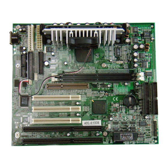
HOW TO USE THIS MANUAL To obtain maximum use from this manual it is suggested: Read Page A COMPONENT LOCATION DIAGRAM where you find the mainboard layout diagram. Please refer to it when you configure the system. Read Page B CHECK LIST OF THE PACKAGING where you find the packing contents. -
Page 3: Apter 1 Introduction
CHAPTER 1 INTRODUCTION 1-1 ATC-6130E Mainboard System Features Intel Pentium II CPU & Celeron CPU operating from 233MHz to 400MHz . ® Intel 82440EX AGPset. Two 3.3V 168-pin DIMM sockets in two banks of 64-bit wide path up to 256MB SDRAM or 512MB EDO DRAM (with parity chip ECC support). -
Page 4: Software Power Off Control
1-2 Software Power Off Control The mainboard design supports Software Power Off Control feature through the SMM code in the BIOS under Windows 95/98, Windows 3.1x, and MS-DOS operation system environment. In order to reach this feature, you should use ATX power supply. First, you should connect the power switch cable to the connector “PS-ON”... -
Page 5: Wake-On-Lan
1-4 Wake-On-LAN The remote Wake-On-LAN mode of operation is a mechanism that uses Advanced Micro Device Magic Packet technology to power up a sleeping workstation on the network. This mechanism is accomplished when the LAN card receives a specific packet of information, called a Magic Packet, addressed to thenode on the network. -
Page 6: Keyboard & Ps/2 Mouse Power On
1-5 Keyboard & PS/2 Mouse Power On The ATC-6130E mainboard has two easy and convenient ways to power up the system. Users may power on the system by typing a password or by double-clicking the PS/2 mouse on the left or right button. It just depends on which one users set in the “Power On function”... -
Page 7: Ldcm ( Landesk Client Manager, Option)
1-7 LDCM (LANDesk Client Manager)(option) If ATC-6130E built-in hardware component support Intel LDCM. LDCM can satisfy users who want manageable systems that can interact automatically with the user. Client manager is the answer, enabling both administrators and clients to manage systems. The... -
Page 8: Chapter 2 Installation
CHAPTER 2 INSTALLATION 2-1 INSTALLATION PROCEDURE Before installing the computer, please prepare all components such as CPU, DRAM; peripherals such as hard drive, keyboard, CD-ROM and accessories such as cables.Then, install the system as following: 1. Plug CPU/ heat sink (refer to Pentium II &... - Page 9 ATC-6130E supports INTEL Pentium ll CPU & Celeron CPU. The ATC-6130E mainboard has built-in VID (Voltage Identify) function to auto detect CPU voltages. Hence you do not have to set the CPU voltage setting. Slot 1 1 2 3 4 DIP switch, (i.e.
-
Page 10: Cpu Setting
2-2-1 CPU SETTING 66MHz CPU Bus Frequency INTERNAL CPU CLOCK 233MHz (66x3.5) 1 2 3 4 266MHz (66x4.0) 1 2 3 4 300MHz (66x4.5) 1 2 3 4 333MHz (66x5.0) 1 2 3 4 366MHz (66x5.5) 1 2 3 4 400MHz (66x6.0) 1 2 3 4 ... -
Page 11: System Memory Installation
2-3 SYSTEM MEMORY INSTALLATION The ATC-6130E provides two 168-pin DIMM sockets for system memory expansion from 8MB to 256MB SDRAM or 512 EDO RAM. These two DIMMs are arranged to two banks, please refer to page A. Each bank provides 64-bit wide data path. -
Page 12: Connectors Description
2-4 CONNECTORS DESCRIPTION The locations of following connectors are indicated in page A. When you plug a cable into the following I/O connectors, you should have the pin 1 edge of the cable align with the pin 1 end of the connector. CONN1 : speaker, keyboard lock, reset, SMI, turbo LED, and IDE LED connectors. - Page 13 FAN : CPU cooling fan connector. Wire with +12V voltage (most likely red wire) must be plugged into pin2, and GROUND wires (most likely black wires) must be plugged into pin3. Please confirm the wire color +12V re-presentation with your supplier. Sense CAUTION: Plug wire into wrong connector will DAMAGE fan and mainboard.
- Page 14 connector. PS/2 mouse : PS/2 mouse header. pin1 : data pin2 : N/C pin3 : GND pin4 : VCC pin5 : clock pin6 : N/C PW1 : ATX mode +3.3/5/12V power supply connector. PW2 : AT (P8/P9) mode power supply connector. 1 3.3V 11 3.3V 16 GND...
- Page 15 FDC1 : this connector is used to connect the floppy drive through a cable. signal signal RWC- 20 STEP- reserved 22 Write Data FDEDIN 24 Write Gate Index- 26 Track 00- 10 Motor EnableA- 28 Write Protect- 12 Drive Sele.B- 30 Read Data- 14 Drive Sele.A- 32 Side 1 Sele.-...
- Page 16 IDE1/IDE2 : these two connectors are used to connect IDE devices through IDE cables, a total of 4 devices can be connected. signal signal Reset IDE DDRQ0(1) Host Data 7 I/O Write- Host Data 8 Host Data 6 I/O Read- Host Data 9 Host Data 5 IORDY...
-
Page 17: Ide Driver Installation
The IDE driver installation procedure is the following : Setup for Windows 95 : 1. Starting Windows 95. 2. Select “START”, “RUN”. 3. Put the diskette into your disk drive: Type “ A:\inf.exe” to install INF.EXE. Type “A:\WIN95\SETUP.EXE”. Or put the CD into your CD-ROM drive: If your CD-ROM drive is D, type “... -
Page 18: Chapter 3 Award Bios Setup
Award BIOS manufacturer provides access to the system BIOS through the hardware and software on each ATC-6130E mainboard. The hardware consists of a Flash ROM and the software is a group of programs that are installed in the ROMBIOS along with all the other data the BIOS must contain. -
Page 19: Update Bios Procedure
3-1 UPDATE BIOS PROCEDURES If the BIOS needs to be updated, you can get a diskette or CD with the updated BIOS driver from your system supplier. The BIOS updated diskette or CD includes : “awdflash.exe” -- BIOS updated utility program “awdflash.doc”... -
Page 20: Update Pentium Ii Microcode Api
3-1-1 UPDATE PENTIUM II BIOS API Intel also provides MICROCODE API(Applications Programming Interface) for Pentium II processor-based mainboard user to updated data block in BIOS quickly and easily. (You can find this utility either in the 3.5“ diskette or CD in the package.) ... -
Page 21: Award System Bios Configuration Setup
To do the SETUP procedure, press the <Del> key when the system is booting up. The following main menu will appear. Please select " STANDARD CMOS SETUP" to enter the next screen. ROM PCI/ISA BIOS (ATC-6130E) CMOS SETUP UTILITY AWARD SOFTWARE, INC. - Page 22 This screen records some basic hardware information, and sets the system clock and error handling. These records can be lost or corrupted if the on- board battery has failed or is weak. ROM PCI/ISA BIOS(ATC-6130E) STANDARD CMOS SETUP AWARD SOFTWARE, INC.
- Page 23 the POST stage and show the IDE for HDD & CD-ROM Drive. If you select ‘user’, you will need to know the information listed below. This information should be from your hard disk vender or dealer. Then enter the figure directly and press <Enter>. If the controller of the HDD interface is ESDI, the selection shall be ‘Type 1’;...
- Page 24 Halt On This category determines whether the computer will stop if an error is detected during power up. No errors The system boot will not be stopped for any error that may be detected All errors When the BIOS detects a non-fatal error the system will be stopped and you will be prompted All, But The system boot will not stop for a keyboard error, it will stop for all...
- Page 25 BIOS FEATURES SETUP This screen is a list of system configuration options. Some of them are defaults required by the mainboard's design, others depend on the features of your system. ROM PCI/ISA BIOS (ATC-6130E) BIOS FEATURES SETUP AWARD SOFTWARE, INC. Virus Warning...
- Page 26 Enabled Activates automatically when the system boots up. If anything attempts to access the boot sector or hard disk, partition table will cause a warning message to appear. Disabled No warning message will appear when anything attempts to access the boot sector or hard disk partition table.
- Page 27 gate A20 is a device used to address memory above 1 MB. Initially, the gate A20 was handled via a pin on the keyboard. Today, while keyboards still provide this support, it is more common and much faster for the system chipset to provide support for gate A20. Normal is keyboard;...
- Page 28 PCI/VGA Palette Snoop It determines whether the MPEG ISA/VESA VGA cards can work with PCI/VGA or not. Enabled When PCI/VGA working with MPEG ISA/VESA VGA Card Disabled When PCI/VGA not working with MPEG ISA/VESA VGA Card Assign IRQ for VGA When this items is enabled, the system will assign an IRQ for VGA.
- Page 29 CHIPSET FEATURES SETUP This screen controls the setting for the chipset on the mainboard. (* the functions are optional, please confirm these with your supplier.) ROM PCI/ISA BIOS (ATC-6130E) CHIPSET FEATURES SETUP AWARD SOFTWARE, INC. Auto Configuration : Enabled SDRAM CAS latency Time...
- Page 30 Precharge Time its data. Normally, DRAM is refreshed entirely as the result of a single request. This option allows you to determine the number of CPU clocks allocated for the Row Address Strobe to accumulate its charge before the DRAM is refreshed. If insufficient time is allowed, refresh may be incomplete and data lost.
- Page 31 Delayed Transaction The chipset has an embedded 32-bit posted write buffer to support delay transactions cycles. Select Enabled to compliance with PCI specification version 2.1….. AGP Aperture Size (MB) Select the size of the AGP aperture. The aperture is a portion of the PCI memory address range dedicated for graphics memory address space.
- Page 32 The following functions are optional, the board must be built-in hardware controller. Please confirm this with your supplier. CPU Warning Temperature. When this item is enabled, we can set the CPU warning temperature . If the CPU temperature is higher than the setting temperature, the system will beep.
- Page 33 POWER MANAGEMENT SETUP This screen controls the 'green' features of this mainboard. ROM PCI/ISA BIOS (ATC-6130E) POWER MANAGEMENT SETUP AWARD SOFTWARE, INC. Power Management : Disabled *Reload Global Timer Events* PM Control by APM : Yes IRQ [3-7, 9-15], NMI :Enabled...
- Page 34 PM Control by APM When enabled, an Advanced Power Management device will be activated to enhance the Max. Power Saving Mode and stop the CPU internal clock. If the Max. Power Saving is not enabled, this will be shown as NO. Video Off Method This determines the manner in which the monitor is blanked.
- Page 35 VGA Active Monitor When Enabled, any video active restarts the global timer for Standby mode. Soft-Off by PWR-BTTN Instant-off : When push the power button, the system power will be off immediately. Delay 4 sec : when push the power button, it will enter suspend mode. We need to push the power button and hold for 4 seconds to turn off the power.
- Page 36 PNP/PCI CONFIGURATION This screen configures the PCI Bus slots. ROM PCI/ISA BIOS (ATC-6130E) PNP/PCI CONFIGURATION AWARD SOFTWARE, INC. PNP OS Installed : No PCI IDE IRQ Map to : PCI-AUTO Resources Controlled by : Auto Primary IDE INT# Reset Configuration Data...
- Page 37 INTEGRATED PERIPHERALS This section page includes all the items of IDE hard drive and Programmed Input/Output features. See also Section “Chipset Features Setup”. ROM PCI/ISA BIOS (ATC-6130E) INTEGRATED PERIPHERALS AWARD SOFTWARE, INC. IDE HDD Block Mode : Enabled Onboard Parallel Port...
- Page 38 allows you to either enable or disable the primary/secondary controller. You might choose to disable the controller if you were to add higher performance or specialized controller. USB Keyboard Support Enabled will support USB keyboard in Win95 2.1 and NT 5.0 or above operating system.
- Page 39 ROM PCI/ISA BIOS (ATC-6130E) CMOS SETUP UTILITY AWARD SOFTWARE, INC. STANDARD CMOS SETUP INTEGRATED PERIPHERALS BIOS FEATURES SETUP SUPERVISOR PASSWORD CHIPSET FEATURES SETUP USER PASSWORD POWER MANAGEMENT SETUP IDE HDD AUTO DETECTION PNP/PCI CONFIGURATION SAVE & EXIT SETUP LOAD BIOS DEFAULTS...
- Page 40 The last second item of the main menu is 'save and exit'. If you select this item and press 'Y', then these records will be saved in the CMOS memory on the mainboard. It will be checked every time when you turn your computer on. ROM PCI/ISA BIOS (ATC-6130E) CMOS SETUP UTILITY AWARD SOFTWARE, INC.
- Page 41 LOAD BIOS DEFAULTS When your mainboard has problems and needs to trouble shoot the system, you can use this function. The default values loaded only affect the BIOS Features Setup, Chipset Features Setup, Power Management Setup and PNP/PCI Configuration Setup. There is no effect on the Standard CMOS Setup. To use this function, select it from main menu and press <Enter>.
- Page 42 ※ Control Key Description ※ UP ARROW ↑ Move to previous item DOWN ARROW ↓ Move to next item LEFT ARROW ← Move to the item in the left hand RIGHT ARROW → Move to the item in the right hand Esc KEY Main Menu : Quit and not save changes Setup menu : Exit current page and return to...
- Page 43 CHECK LIST OF THE PACKAGING The mainboard comes securely packed in a durable box or shipping carton. If any of the following items are missing or damaged, please contact your supplier. Each mainboard contains: Q'TY Description Mainboard : ATC-6130. CD(option) : LDCM, Enhanced IDE driver Award system BIOS Update Utility Diskette(option) : Enhanced IDE driver...
Need help?
Do you have a question about the ATC-6130E and is the answer not in the manual?
Questions and answers