Table of Contents
Advertisement
Quick Links
CONTENTS
INDEX .......................................................................................... A
HOW TO USE THIS MANUAL.....................................2
HARDWARE............................................................3
INSIDE THE ATC-6510 MAINBOARD PACKAGE............4
1-1 Soft-Off-Control..............................................................................5
1-2 LDCM ( LANDesk Client Manager, option) ............................... .6
1-3 Thermister (option)........................................................................ .7
1-4 Wake-On-LAN.............................................................................. .7
1-5 SB-Link Sideband Signals (JP3).......................................8
2-1 Installation Procedure ................................................................. .9
2-2 CPU Installation............................................................................ .10
2-3 System Memory Installation............................................16
2-4 Connectors Description................................................................. .17
2-5 IDE Driver Installation ................................................................. .22
3-1 Update BIOS Procedure................................................................ .24
3-1-1 Update Pentium II microcode API..................................25
3-2 Award System BIOS Configuration Setup ................................... .26
Appendix A ..............................................................56
Appendix B How to Install Pentium II CPU ? &
How to Install Celeron CPU ?
Appendix C How to Setup Thermister (option) ?
HOW TO USE THIS MANUAL
Introduction.........................................5
Installation....................................................... 9
Award BIOS Setup ......................................... 23
1
Advertisement
Table of Contents

Related Manuals for A-Trend ATC-6510


Summary of Contents for A-Trend ATC-6510
-
Page 1: Table Of Contents
CONTENTS INDEX ..................A HOW TO USE THIS MANUAL……………………………….2 INTRODUCTION TO THE ATC-6510 MAINBOARD HARDWARE……………………………………………………3 INSIDE THE ATC-6510 MAINBOARD PACKAGE………...4 CHAPTER 1 Introduction…………………………………..5 1-1 Soft-Off-Control................5 1-2 LDCM ( LANDesk Client Manager, option) ....... .6 1-3 Thermister (option)................ .7 1-4 Wake-On-LAN................7 1-5 SB-Link Sideband Signals (JP3)…………………………………8... -
Page 2: Introduction To The Atc-6510 Mainboard Hardware
Read about an overview of the mainboard features, packing contents, and how to upgrade as well as to change hardware configurations such as memory size, CPU type, jumper settings lists and connectors in the following categories: INTRODUCTION TO THE ATC-6510 MAINBOARD HARDWARE INSIDE THE ATC-6510 MAINBOARD PACKAGE Chapter 1 Introduction... -
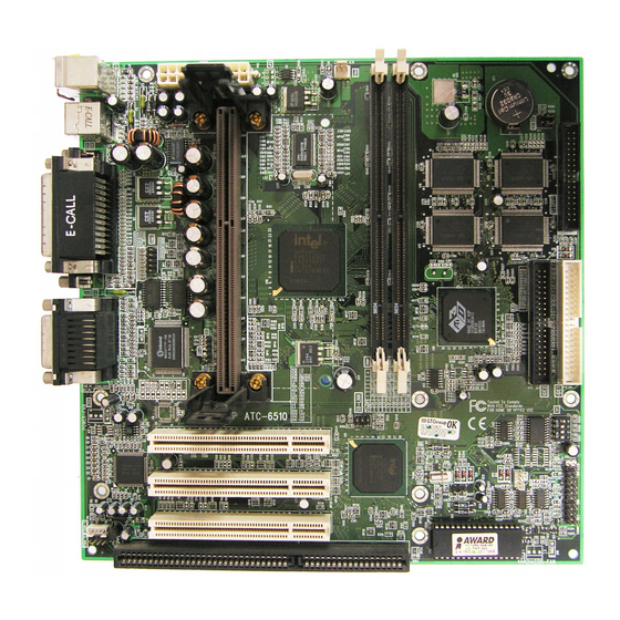
Page 3: Inside The Atc-6510 Mainboard Package
HARDWARE Each ATC-6510 mainboard supports or contains the following components: ! INTEL Pentium II CPU operating from 233MHz up to 333MHz. ! INTEL Celeron CPU operating from 266MHz up to 333MHz. ! INTEL 440EX PCIset. ! ATI AGP Rage IIC 3D VGA chipset. -
Page 4: Chapter 1 Introduction
The mainboard comes securely packed in a durable box and shipping carton. If any of the following items are missing or damaged, please contact your supplier. Each mainboard contains: Q'TY Description Mainboard : ATC-6510. Retention mechanism (for Pentium II installation) CD(option) : LDCM, Enhanced IDE driver Award system BIOS Update Utility Diskette(option) -
Page 5: Ldcm ( Landesk Client Manager, Option)
The ATC-6510 mainboard has ATI AGP Rage IIC 3D VGA chipset, Yamaha 719/715 IIC 3D stereo sound PnP chipsets and SGRAM (option) onboard. The ATI AGP Rage IIC 3D VGA chipset using AGP interface technique which allows users could have 3D display resolution without plug any of VGA cards and the Yamaha 719/715 IIC 3D stereo sound PnP chipset using ISA interface which could let your system has 3D stereo sound. - Page 6 ATC-6510 built-in controller(option) support Intel LDCM. LDCM can satisfy users who want manageable systems that can interact automatically with the user. Client manager is the answer, enabling both administrators and clients to manage systems. The features of LDCM are as following : ※...
-
Page 7: Thermister (Option)
1-3 Thermister (option) This means that users can monitor the CPU temperature through thermister. When setting up the thermister, the BIOS will load the CPU temperature automatically. There is a choice of the warning beep sound if users set the option on. If the CPU temperature overheated, users will get the notice from the thermister. -
Page 8: Sb-Link Sideband Signals (Jp3)
1-5 SB-LINK Sideband Signals (JP3) In order to migrate the legacy Sound Blaster compatible audio to the PCI bus, EMU8008 incorporates a pair of SB-Link request/grant sideband signals (PCPCIR EQ#A and PCPCISIRQ) to interface to the PCI bus. SB-Link is a mechanism that was defined and developed by Creative as a docking solution which allows ISA slots to exist in docking stations connected to desktop PC PCI bus. -
Page 9: Chapter 2 Installation
7. If all of above procedures are success, turn-off the power then plug all of them into your computer case. Remark : Before you do the mainboard installation, please keep in mind that VGA and Sound chipsets are built-in on the ATC-6510 mainboard along with MicroATX Form Factor. -
Page 10: Cpu Installation
The 6510 mainboard supports both INTEL Pentium II CPU and Celeron CPU. 2-2-1 CPU TYPE SELECTION (by BIOS) 1.Press the <Del> key when the system is booting up. 2.The following main menu will appear. ROM PCI/ISA BIOS (ATC-6510) CMOS SETUP UTILITY AWARD SOFTWARE, INC. STANDARD CMOS SETUP... - Page 11 BIOS screen. Or user can clear CMOS to reset the BIOS value. Also the ATC-6510 mainboard supports keyboard power on or mouse power on function, (refer to ‘Integrated Peripherals’, page48,49).
- Page 12 5a. Intel Pentium II 233MHz (66 x 3.5) ROM PCI/ISA BIOS (ATC-6510) CHIPSET FEATURES SETUP AWARD SOFTWARE, INC. Auto Configuration : Enabled SDRAM CAS latency Time DRAM Speed Selection : 60 ns CPU Clock Ratio : 3.5x MA Wait State...
- Page 13 5b. Intel Pentium II 266MHz (66 x 4.0) ROM PCI/ISA BIOS (ATC-6510) CHIPSET FEATURES SETUP AWARD SOFTWARE, INC. Auto Configuration : Enabled SDRAM CAS latency Time DRAM Speed Selection : 60 ns CPU Clock Ratio : 4.0x MA Wait State...
- Page 14 5c. Intel Pentium II 300MHz (66 x 4.5) ROM PCI/ISA BIOS (ATC-6510) CHIPSET FEATURES SETUP AWARD SOFTWARE, INC. Auto Configuration : Enabled SDRAM CAS latency Time DRAM Speed Selection : 60 ns CPU Clock Ratio : 4.5x MA Wait State...
- Page 15 5d. Intel Pentium II 333MHz (66 x 5.0) ROM PCI/ISA BIOS (ATC-6510) CHIPSET FEATURES SETUP AWARD SOFTWARE, INC. Auto Configuration : Enabled SDRAM CAS latency Time DRAM Speed Selection : 60 ns CPU Clock Ratio : 5.0x MA Wait State...
- Page 16 5e. Intel Celeron CPU 266MHz (66 x 4.0) ROM PCI/ISA BIOS (ATC-6510) CHIPSET FEATURES SETUP AWARD SOFTWARE, INC. Auto Configuration : Enabled SDRAM CAS latency Time DRAM Speed Selection : 60 ns CPU Clock Ratio : 4.0x MA Wait State...
- Page 17 5f. Intel Celeron CPU 300MHz (66 x 4.5) ROM PCI/ISA BIOS (ATC-6510) CHIPSET FEATURES SETUP AWARD SOFTWARE, INC. Auto Configuration : Enabled SDRAM CAS latency Time DRAM Speed Selection : 60 ns CPU Clock Ratio : 4.5x MA Wait State...
- Page 18 5g. Intel Celeron CPU 333MHz (66 x 5.0) ROM PCI/ISA BIOS (ATC-6510) CHIPSET FEATURES SETUP AWARD SOFTWARE, INC. Auto Configuration : Enabled SDRAM CAS latency Time DRAM Speed Selection : 60 ns CPU Clock Ratio : 5.0x MA Wait State...
-
Page 19: System Memory Installation
2-3 SYSTEM MEMORY INSTALLATION The ATC-6510 provides two 168-pin DIMM sockets for system memory expansion from 8MB to 256MB. These two DIMMs are arranged to two banks, please refer to page A. Each bank provides 64-bit wide data path. ※ ※ ※ ※ Samples of System Memory Combinations Options ※ ※ ※ ※... -
Page 20: Connectors Description
2-4 CONNECTORS DESCRIPTION The locations of following connectors are indicated in page A. When you plug wires into the following connector of CONN1, you should have the pin 1 edge of the wires align with the pin 1 end of the connector. CONN1 : speaker, keyboard lock, reset, SMI, turbo LED, and IDE LED connectors. - Page 21 IDE-LED : IDE devices indicator LED connector. IDE-LED stays ON indicates LED signal on-board IDE devices in operation. red wire of the HDD connector must Pin 12 PS_ON : Power Button Pin 24 Pin 12 : PS_ON Pin 24 : +5VSB (2) Chassis FAN (1) CPU FAN Slot 1...
- Page 22 PW1 : ATX mode +3.3/5/12V power supply connector. 1 3.3V 11 3.3V 16 GND 2 3.3V 12 -12V 17 GND 3 GND PWRGD 13 GND 18 -5V 4 +5V 5VSB 14* PS_ON 19 +5V 5 GND 10 +12V 15 GND 20 +5V * PS_ON : Soft-Off power control COM1/COM2 : these two connectors are...
- Page 23 LPT : this connector is used to connect parallel Slot 1 port cable. Signal Signal STROBE- ACK- Data Bit 0 BUSY Data Bit 1 Data Bit 2 SLCT Data Bit 3 Auto Feed- Data Bit 4 ERROR- Data Bit 5 INIT- Data Bit 6 SLCT IN-...
- Page 24 IDE1/IDE2 : these two connectors are used to connect IDE devices through IDE cables, a total of 4 devices can be connected. signal Signal Reset IDE DDRQ0(1) Host Data 7 I/O Write- Host Data 8 Host Data 6 I/O Read- Host Data 9 Host Data 5 IORDY...
-
Page 25: Ide Driver Installation
2-5 IDE DRIVER INSTALLATION The IDE driver installation procedure is as following : Setup for Windows 95 : 1. Starting Windows 95 2. Select “START”, “RUN”. 3. Install INF.EXE before you install IDE driver, please refer to readme file. 4. Type “A:\WIN95\SETUP.EXE”. If the installation is to be done from CD-ROM, put the All-In-One CD into your CD-ROM drive;... - Page 26 2-6 VGA & SOUND DRIVER INSTALLATION The All-In-One CD contains “readme.txt”, “Ati AGP Driver”, “Yamaha 715 ISA driver” and “Yamaha 724 PCI driver” four application programs.
-
Page 27: Chapter 3 Award Bios Setup
Award BIOS manufacturer provides access to the system BIOS through the hardware and software on each ATC-6510 mainboard. The hardware consists of a Flash ROM and the software is a group of programs that are installed in the ROMBIOS along with all the other data the BIOS must contain. -
Page 28: Update Bios Procedure
3-1 UPDATE BIOS PROCEDURE If the BIOS needs to be updated, you can get a diskette with the updated BIOS from your system supplier. The BIOS diskette includes : “awdflash.exe” -- BIOS update utility program “awdflash.doc” “(update BIOS filename with version number).bin” The update procedure is as following: 1. -
Page 29: Update Pentium Ii Microcode Api
3-1-1 UPDATE PENTIUM II MICROCODE API Intel also provides MICROCODE API(Applications Programming Interface) for Pentium II processor-based mainboard user to update data block in BIOS quickly and easily. (You can find this utility in the All-In-One CD in the mainboard package). The BIOS code on the Pentium II processor-based mainboards contains data that is specific to each silicon stepping of the processor. - Page 30 (ROM) on the mainboard. To do the SETUP procedure, press the <Del> key when the system is booting up. The following main menu will appear. Please select " STANDARD CMOS SETUP" to enter the next screen. ROM PCI/ISA BIOS (ATC-6510) CMOS SETUP UTILITY AWARD SOFTWARE, INC.
- Page 31 This screen records some basic hardware information, and sets the system clock and error handling. These records can be lost or corrupted if the on-board battery has failed or is weak. ROM PCI/ISA BIOS (ATC-6510) CMOS SETUP UTILITY AWARD SOFTWARE, INC.
- Page 32 Date The date format is <day>, <date><month><year>. Press<F3> to show the calendar. The day, from Sun to Sat, determined by the BIOS and is display-only Date The date, from 1 to 31 Month The month, Jan. through Dec. Year The year, from 1900 to 2099 Time The time format is <hour><minute><second>.
- Page 33 Drive A This category identifies the types of floppy disk drive Drive B A or drive B that have been installed in the computer. None No floppy drive installed 360K, 5.25 in 5.25“ PC-type 360KB capacity 1.2M, 5.25 in 5.25“ AT-type 1.2MB capacity 720K, 3.5 in 3.5“...
- Page 34 Memory This category is display-only which is determined by POST (Power On Self Test) of the BIOS. Base Memory The POST will determine the amount of base (or conventional) memory installed in the system. The value of the base memory is typically 512K or 640K based on the memory installed on the motherboard.
- Page 35 This screen is a list of system configuration options. Some of them are defaults required by the mainboard's design, others depend on the features of your system. ROM PCI/ISA BIOS (ATC-6510) CMOS SETUP UTILITY AWARD SOFTWARE, INC. STANDARD CMOS SETUP...
- Page 36 Virus Warning When this item is enabled, the Award BIOS will monitor the boot sector and partition table of the hard disk drive for any attempt at modification. If an attempt is made, the BIOS will halt the system and the following error message will appear. Afterwards, if necessary, you will be able to run an antivirus program to locate and remove the problem before any damage is done.
- Page 37 Boot Sequence This category determines which drive is to search first for the Disk Operating System (i.e., DOS). A, C, SCSI System will first search for floppy disk drive then hard disk drive, and the next is SCSI device. C, A, SCSI System will first search for hard disk drive then floppy disk drive, and the next is SCSI device.
- Page 38 Boot Up This allows you to determine the default state of NumLock Status the numeric keypad. By default, the system boots up with NumLock on. Keypad is numeric keys Keypad is arrow keys Boot Up System Selects the default system speed - the normal Speed operating speed at power up.
- Page 39 Typematic Delay When the typematic rate is enabled, this section (Msec) allows you select the delay between when the key was first depressed and when the acceleration begins. 250 msec 500 msec 750 msec 1000 1000 msec Security Option This category allows you to limit access to the system and Setup, or just to Setup.
- Page 40 SCSI. Shadow The choice : Enabled/Disabled Notice that the ATC-6510 mainboard is subdivided into two models. The first model of the ATC-6510 mainboard built-in Hardware Health Monitoring ie Winbond 83781. The second model of the ATC-6510 mainboard did not built-in Hardware Health Monitoring.
- Page 41 This screen controls the setting for the chipset on the mainboard. ROM PCI/ISA BIOS (ATC-6510) CMOS SETUP UTILITY AWARD SOFTWARE, INC. STANDARD CMOS SETUP INTEGRATED PERIPHERALS BIOS FEATURES SETUP SUPERVISOR PASSWORD CHIPSET FEATURES SETUP USER PASSWORD POWER MANAGEMENT SETUP IDE HDD AUTO DETECTION PNP/PCI CONFIGURATION SAVE &...
- Page 42 Auto The first chipset settings deal with CPU access to dynamic Configuration random access memory (DRAM). The default timings have been carefully chosen and should only be altered if data is being lost. Such a scenario might well occur if your system had mixed speed DRAM chips installed so that greater delays may be required to preserve the integrity of the data held in the slower memory chips.
- Page 43 System BIOS Select Enabled allows caching of the system BIOS ROM at Cacheable F0000h-FFFFFh, resulting in better system performance. However, if any program writes to this memory area, a system error may result. Video BIOS Select Enabled allows caching of the video BIOS ROM at Cacheable F0000h-FFFFFh, resulting in better system performance.
- Page 44 AGP Aperture Select the size of the AGP aperture. The aperture is a portion of Size (MB) the PCI memory address range dedicated for graphics memory address space. Host cycle that hit the aperture range are forwarded to the AGP without any translation. See for AGP information.
- Page 45 ※ ※ ※ ※ ※ ※ ※ ※ NOTE Press “ Del ” to enter BIOS setup and set the CPU clock frequency / CPU clock ratio to correct value. The following functions are optional, and they show only when the monitoring IC exists on the mainboard.
- Page 46 This screen controls the 'green' features of this mainboard. ROM PCI/ISA BIOS (ATC-6510) CMOS SETUP UTILITY AWARD SOFTWARE, INC. STANDARD CMOS SETUP INTEGRATED PERIPHERALS BIOS FEATURES SETUP SUPERVISOR PASSWORD CHIPSET FEATURES SETUP USER PASSWORD POWER MANAGEMENT SETUP IDE HDD AUTO DETECTION PNP/PCI CONFIGURATION SAVE &...
- Page 47 Power This category allows you to select the type (or Management degree) of power saving and is directly related to the following modes : Doze; Standby; Suspend; HDD Power Down. Min. Power Minimum power management. Doze =1hr.; Saving Standby=1hr.; Suspend=1hr.; HDD Power Down=15min Max.
- Page 48 Video off After When enabled, this feature allows the VGA adapter to operate in a power saving mode. Monitor will remain on during power saving modes. Suspend Monitor blanked when the systems enters the Suspend mode. Standby Monitor blanked when the system enters Standby mode. Doze Monitor blanked when the system enters any power saving mode.
- Page 49 Soft-Off by Instant-off : When push the power button, the system power will PWR-BTTN be off immediately. Delay 4 sec : when push the power button, it will enter suspend mode. We need to push the power button and hold for 4 seconds to turn off the power. CPUFAN Off Enabled : under suspend mode, the CPU FAN will be turn off.
- Page 50 This screen configures the PCI Bus slots. ROM PCI/ISA BIOS (ATC-6510) CMOS SETUP UTILITY AWARD SOFTWARE, INC. STANDARD CMOS SETUP INTEGRATED PERIPHERALS BIOS FEATURES SETUP SUPERVISOR PASSWORD CHIPSET FEATURES SETUP USER PASSWORD POWER MANAGEMENT SETUP IDE HDD AUTO DETECTION PNP/PCI CONFIGURATION SAVE &...
- Page 51 PNP OS Installed This item allows you to determine PnP OS or not. Choices are Yes or No. Resource The Award Plug and Play BIOS has the capability to Controlled by automatically configure all of the boot and Plug and Play compatible devices.
- Page 52 This section page includes all the items of IDE hard drive and Programmed Input/Output features. See also Section “Chipset Features Setup”. ROM PCI/ISA BIOS (ATC-6510) CMOS SETUP UTILITY AWARD SOFTWARE, INC. STANDARD CMOS SETUP INTEGRATED PERIPHERALS BIOS FEATURES SETUP SUPERVISOR PASSWORD...
- Page 53 IDE HDD Block This allows your HD controller to use the fast block Mode mode to transfer data to and from your HD drive Enabled IDE controller uses block mode Disabled IDE controller uses standard mode IDE Primary PIO - Programmed Input/Output, it allows the BIOS to Master/Slave PIO tell the controller what it wants and then let the controller IDE Secondary...
- Page 54 Hot Key : when user select this option, it will show another line lines as Hot Key Power ON: Ctrl-F1”’ select any one you like. After power off, if user key in the control-F, it will power up the system. Mouse Left, Mouse Right : it will power up the system by double click the left or right mouse.
- Page 55 ROM PCI/ISA BIOS (ATC-6510) CMOS SETUP UTILITY AWARD SOFTWARE, INC. STANDARD CMOS SETUP INTEGRATED PERIPHERALS BIOS FEATURES SETUP SUPERVISOR PASSWORD CHIPSET FEATURES SETUP USER PASSWORD POWER MANAGEMENT SETUP IDE HDD AUTO DETECTION PNP/PCI CONFIGURATION SAVE & EXIT SETUP LOAD BIOS DEFAULTS...
- Page 56 The last step is 'save and exit'. If you select this item and press 'Y', then these records will be saved in the CMOS memory on the mainboard. It will be checked every time you turn your computer on. ROM PCI/ISA BIOS (ATC-6510) CMOS SETUP UTILITY AWARD SOFTWARE, INC.
- Page 57 LOAD BIOS DEFAULTS When your mainboard has problems and needs to trouble shoot the system, you can use this function. The default values loaded only affect the BIOS Features Setup, Chipset Features Setup, Power Management Setup and PNP/PCI Configuration Setup. There is no effect on the Standard CMOS Setup.
- Page 58 CAUTION :If you forgot your password, you must disable the CMOS by turning power off and set JP 8 to ‘close‘. And then open reload the system. IDE HDD AUTO DETECTION This allows you to detect the IDE hard disk drivers‘ parameters and enter them into ‘Standard CMOS Setup’...
- Page 59 ※ ※ ※ ※ Control Key Description ※ ※ ※ ※ ↑ UP ARROW Move to previous item DOWN ARROW ↓ Move to next item ← LEFT ARROW Move to the item in the left hand RIGHT ARROW → Move to the item in the right hand Esc KEY Main Menu : Quit and not save changes...
- Page 60 If the mainboard doesn't function properly, please complete the following information and return it to your system dealer. If the further information is needed, please attach it. Model No : ATC-6510 Date of Purchase : ______________ Serial No : ___________________...
Need help?
Do you have a question about the ATC-6510 and is the answer not in the manual?
Questions and answers