Table of Contents
Advertisement
Table of Contents
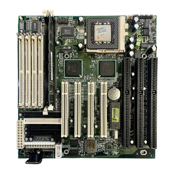
JUMPER COMPONENT LOCATION DIAGRAM.................A
CHAPTER 1 INTRODUCTION..........................................2
1-1 System features..................................................................3
1-2 Software power off control..................................................4
1-3 Check list of the packing.....................................................5
1-4 Wake-On-LAN..........................................................6
CHAPTER 2 INSTALLATION...........................................7
2-1 Installation procedures .......................................................7
2-2 CPU installation..................................................................8
2-3 System memory installation................................................20
2-4 SRAM installation................................................................22
description .........................................................................23
2-6 IDE driver installation..........................................................28
CHAPTER 3 AWARD BIOS SETUP.................................29
3-1 Update BIOS procedures....................................................30
3-2 Award system BIOS configuration setup............................31
APPENDIX A ......................................................................56
Advertisement
Table of Contents

Related Manuals for A-Trend ATC-5030


Summary of Contents for A-Trend ATC-5030
-
Page 1: Table Of Contents
Table of Contents JUMPER COMPONENT LOCATION DIAGRAM....A CHAPTER 1 INTRODUCTION..........2 1-1 System features..............3 1-2 Software power off control..........4 1-3 Check list of the packing.............5 1-4 Wake-On-LAN………………………………………………….6 CHAPTER 2 INSTALLATION...........7 2-1 Installation procedures ............7 2-2 CPU installation..............8 2-3 System memory installation..........20 2-4 SRAM installation..............22 2-5 Other jumpers and connectors description .................23... -
Page 2: Chapter 1 Introduction
Your system dealer will set up the ATC-5030 mainboard according to your demand of the computer. It means that the current settings of your ATC-5030 mainboard may not be the same as the defaults shown in this user's manual. If you need to change your configuration, please ask your dealer first. -
Page 3: System Features
1-1 SYSTEM FEATURES Supports Intel Pentium (P54C) CPU operating at 90MHz to 200MHz & Intel Pentium MMX 166~233MHz (P55C), AMD K5, AMD K6, Cyrix 6x86MX , 6x86L. INTEL 430TX PCIset. Using four 72-pin SIMM sockets, provides two banks of 64-bit wide path up to 256MB addressing page mode DRAMs. - Page 4 1-2 SOFT-OFF CONTROL (option) The ATC-5030 mainboard design supports Soft-Off Control feature through the SMM code in the BIOS under Windows 95, Windows 3.1x, and MS-DOS operation system environment. It needs to use ATX power supply. (please contact your supplier for...
-
Page 5: Check List Of The Packing
Award system BIOS driver Update Utility Cable : Enhanced IDE connector. Cable : F.D.D. connector. Cable : Serial port. Cable : Serial/Parallel. Manual : User`s manual. NOTE : Leave the ATC-5030 mainboard in its original packing until you are ready to install it. -
Page 6: Wake-On-Lan
1-5 Wake-On-LAN The remote Wake-On-LAN mode of operation is a mechanism that uses Advanced Micro Device Magic Packet technology to power up a sleeping workstation on the network. This mechanism is accomplished when the LAN card receives a specific packet of information, called a Magic Packet, addressed to thenode on the network. -
Page 7: Chapter 2 Installation
CD-ROM drive; and accessories such as cables. Then, install the system as following : 1. Plug CPU, heat sink, cooling fan, and DRAM modules in the ATC-5030 mainboard. 2. Set jumpers based on your configuration. 3. Plug add-on cards in PCI/ISA slots. -
Page 8: Cpu Installation
CPU type/brand and follow the description to setup DIP Switch (SW1). If your CPU is not in the list of 2-2-1, please refer to 2-2-2 and 2-2-3 for installation. The ATC-5030 mainboard provides auto-detection function to detect CPU core voltages and... - Page 9 2-2-1 CPU TYPE SELECTION The DIP switch 1 on the ATC-5030 motherboard is to adjust the CPU internal clocks by using external CPU frequencies techniques for all brands of the CPU. A. INTEL PENTIUM CPU (P54C) ※ P54C VRE : 3.400V ~ 3.600V...
- Page 10 Intel Pentium 90MHz INTERNAL CPU Ext.x Frq. CLOCK 90MHz 60 x 1.5 1 2 3 4 5 6 Intel Pentium 100MHz INTERNAL CPU Ext.x Frq. CLOCK 100MHz 66 x 1.5 1 2 3 4 5 6 Intel Pentium 120MHz INTERNAL CPU Ext.x Frq.
- Page 11 Intel Pentium 150MHz INTERNAL CPU Ext.x Frq. CLOCK 150MHz 60 x 2.5 1 2 3 4 5 6 Intel Pentium 166MHz INTERNAL CPU Ext.x Frq. CLOCK 166MHz 66 x 2.5 1 2 3 4 5 6 Intel Pentium 180MHz INTERNAL CPU Ext.x Frq.
- Page 12 B. INTEL PENTIUM MMX CPU (P55C) B-1. Intel Pentium MMX 166MHz INTERNAL CPU Ext.x Frq. CLOCK 166MHz 66 x 2.5 1 2 3 4 5 6 B-2. Intel Pentium MMX 200MHz INTERNAL CPU Ext.x Frq. CLOCK 200MHz 66 x 3.0 1 2 3 4 5 6 B-3.
- Page 13 C. Cyrix 6x86(028) CPU C-1. Cyrix 6x86MX PR150 @ 60 Bus 2x INTERNAL CPU Ext.x Frq. CLOCK PR150MHz 60 x 2.0 1 2 3 4 5 6 C-2. Cyrix 6x86MX PR166 @ 66 Bus 2x INTERNAL CPU Ext.x Frq. CLOCK PR166MHz 66 x 2.0 1 2 3 4 5 6...
- Page 14 C-4. Cyrix 6x86MX PR200 @ 66 Bus 2.5x INTERNAL CPU Ext.x Frq. CLOCK PR200MHz 66 x 2.5 1 2 3 4 5 6 C-5. Cyrix 6x86MX PR200 @ 75 Bus 2x INTERNAL CPU Ext.x Frq. CLOCK PR200MHz 75 x 2.0 1 2 3 4 5 6 C-6.
- Page 15 D. Cyrix 6x86L CPU (dual voltage) D-1. Cyrix 6x86L PR150+ INTERNAL CPU Ext.x Frq. CLOCK PR150+MHz 60 x 2.0 1 2 3 4 5 6 D-2. Cyrix 6x86L PR166+ INTERNAL CPU Ext.x Frq. CLOCK PR166+MHz 66 x 2.0 1 2 3 4 5 6 D-3.
- Page 16 E. AMD-K5 CPU Series E-1. AMD-K5 PR90 INTERNAL CPU Ext.x Frq. CLOCK PR90MHz 60 x 1.5 1 2 3 4 5 6 E-2. AMD-K5 PR100 INTERNAL CPU Ext.x Frq. CLOCK PR100MHz 66 x 1.5 1 2 3 4 5 6 E-3.
- Page 17 E-4. AMD-K5 PR133 INTERNAL CPU Ext.x Frq. CLOCK PR133MHz 66 x 2.0 1 2 3 4 5 6 E-5. AMD-K5 PR166 INTERNAL CPU Ext.x Frq. CLOCK PR166MHz 60 x 2.5 1 2 3 4 5 6 F. AMD-K6 CPU F-1. AMD-K6 166ALR INTERNAL CPU Ext.x Frq.
- Page 18 F-2. AMD-K6 200 ALR INTERNAL CPU Ext.x Frq. CLOCK 200 ALR (MHz) 66 x 3.0 1 2 3 4 5 6 F-3. AMD-K6-233 ANR CPU : 3.2V INTERNAL CPU Ext.x Frq. CLOCK 233 ANR (MHz) 66 x 3.5 1 2 3 4 5 6...
- Page 19 2-2-2 CPU Voltage, CPU Bus Clock and Bus Freq. Ratio Setting A. CPU Bus Clock : Clock Gen. CPU Bus Clock: 6 Pin DIP-SW (Option) 2x6 Header 2x3 Header BASE CLK SW1-6 (JP9) SW1-5 (JP10) SW1-4 (JP11) 60MHz 66MHz 75MHz 83MHz B.
-
Page 20: System Memory Installation
2-3 SYSTEM MEMORY INSTALLATION ATC-5030 provides four 72-pin SIMM sockets for system memory expansion from 4MB to 256MB. These four SIMMs are arranged to two banks, Bank0 (SIM 1, 2) and Bank1(SIM 3, 4), please refer to page A. Each bank provides 64-bit wide data path. - Page 21 ※ System Memory Combinations Options ※ BANK0 BANK1 Total Memory SIM 1, 2 SIM 3, 4 SIM 1- 4 4MBx2 4MBx2 8MBx2 16MB 8MBx2 16MB 4MBx2 4MBx2 16MB 4MBx2 8MBx2 24MB 8MBx2 4MBx2 24MB 16MBx2 32MB 16MBx2 32MB 8MBx2 8MBx2 32MB 4MBx2 16MBx2...
-
Page 22: Sram Installation
16MBx2 64MBx2 160MB 64MBx2 16MBx2 160MB 32MBx2 64MBx2 192MB 64MBx2 32MBx2 192MB 64MBx2 64MBx2 256MB *128MBx2 256MB *128MBx2 256MB * Please confirm this with your supplier firstly. 2-4 SRAM INSTALLATION ATC-5030 is built-in 512KB Sync. Pipeline Burst SRAM on board... -
Page 23: Other Jumpers And Connectors
2-5 OTHER JUMPERS AND CONNECTORS DESCRIPTION When you plug a cable into the following I/O connectors, you should have the pin 1 edge of the cable aligned with the pin 1 end of the connector. CONN1 : speaker, power LED, reset, SMI, turbo LED, and IDE LED connectors. - Page 24 TB-LED : Turbo LED indicator IDE-LED : IDE devices indicator LED connector. IDE-LED stays ON indicates +5V on-board IDE devices in operation. If GND plug wire into wrong connector, color of LED will be lighter and the IDE dvices can still function properly. FAN1 : CPU cooling fan connector.
- Page 25 USB1 : USB connector; Universal Serial Bus;this is used to connect USB devices through an (red) optional dual head cable with a iron plane. OC0 and OC1 are used to mention the status D1 - D0 + of the USB power supply lines. D0 - CAUTION: Plug wire into wrong connector...
- Page 26 PW1 : AT mode +5 Voltage power supply connector.(P8,P9) PG +12V +5V -12V PW2 : ATX mode +3.3/5/12V power supply connector.(optional) 1 3.3V 11 3.3V 16 GND 2 3.3V 12 -12V 17 GND 3 GND PWRGD 13 GND 18 -5V 4 +5V 5VSB PS_ON 19 +5V...
- Page 27 COM1/COM2 : these two connectors are used to connect serial port cables. signal name Serial In Serial Out COM1/COM2...
- Page 28 FDC : this connector is used to connect floppy disk drive through cable. signal signal RWC- 20 STEP- reserved 22 Write Data FDEDIN 24 Write Gate Index- 26 Track 00- 28 Write Protect- Motor EnableA- 12 Drive Sele.B- 30 Read Data- 14 Drive Sele.A- 32 Side 1 Sele.- Motor EnableB-...
- Page 29 IDE1/IDE2 : these two connectors are used to connect max. 4 devices through IDE cable. signal signal Reset IDE DDRQ0(1) Host Data 7 I/O Write- Host Data 8 Host Data 6 I/O Read- Host Data 9 Host Data 5 IORDY Host Data 10 Host Data 4 DDAK0-(1-)
-
Page 30: Ide Driver Installation
2-6 IDE DRIVER INSTALLATION Setup for Windows 95 : (Windows 95 version 950/950a/950b) 1. Starting Windows 95 2. Select “START”, “RUN”. 3. Install INF.EXE before you install IDE driver, please refer to readme file. 4. Type “A:\WIN95\SETUP.EXE”. 5. Restart computer, then follow the instructions on your screen to install new IDE driver we offer in the 3.5“... -
Page 31: Chapter 3 Award Bios Setup
ATC-5030 uses Flash ROM to make BIOS easier to be updated by the floppy disk-based program and to committe Microsoft Windows 95 plug & play feature. -
Page 32: Update Bios Procedures
3-1 UPDATE BIOS PROCEDURES If the BIOS needs to be updated, it can be obtained on a diskette from your system supplier. The BIOS diskette includes 3 files: “awdflash.exe” -- BIOS update utility program “awdflash.doc” “(update BIOS filename with version number).bin” The update procedures are as following: 1. -
Page 33: Award System Bios Configuration Setup
Enter the SETUP procedure, press the <Del> key when the system is booting up. The following main menu will appear. Please select " STANDARD CMOS SETUP" to enter the next screen. ROM PCI/ISA BIOS (ATC-5030) CMOS SETUP UTILITY AWARD SOFTWARE, INC. STANDARD CMOS SETUP... - Page 34 This screen records some basic hardware information, and set the system clock and error handling. These records can be lost or corrupted if the on-board battery is failed or weak. ROM PCI/ISA BIOS (ATC-5030) CMOS SETUP UTILITY AWARD SOFTWARE, INC.
- Page 35 Date mm is month, dd is date, yy is year. date from 1 to 31 month from Jan. to Dec. year from 1900 to 2099 Time hh is hour, mm is minute, ss is second. from 0 to 23 (24-hour military -time) from 1 to 59 from 1 to 59 Primary Master...
- Page 36 Drive A The category identifies the types of floppy Drive B disk drive A or drive B that have been installed in the computer. None No floppy drive installed 360K, 5.25 in 5.25“ PC-type 360KB capacity 1.2M, 5.25 in 5.25“ AT-type 1.2MB capacity 720K, 3.5 in 3.5“...
- Page 37 Memory The category is display-only which is deter- mined by POST (Power On Self Test) of the BIOS. Base Memory The value of the base memory is typically 512K or 640K based on the memory installed on the mainboard. Extended Memory How much extended memory is present during the POST.
- Page 38 This screen is a list of system configuration options. Some of them are defaults required by the mainboard's design, others depend on the features of your system. ROM PCI/ISA BIOS (ATC-5030) CMOS SETUP UTILITY AWARD SOFTWARE, INC. STANDARD CMOS SETUP...
- Page 39 Virus Warning When this item is enabled, the BIOS will monitor the boot sector and partition table of the hard disk drive for any attempt at modification. If an attempt is made, the BIOS will halt the system and the following error message will appear.
- Page 40 Swap Floppy This item allows you to determine whether Drive enable the swap floppy drive or not. Boot Up Floppy During POST, BIOS will determine if the Seek floppy disk drive installed is 40 tracks (360K) or 80 tracks (720K, 1.2M, 1.44M) Enabled BIOS searchs for floppy disk drive to determine if it is 40 or 80 tracks...
- Page 41 Typematic Delay When the typematic rate is enabled, this (Msec) section allows you select the delay between when the key was first depressed and when the acceleration begins. 250 msec 500 msec 750 msec 1000 1000 msec Security Option This category allows you to limit access to the system and Setup, or just to Setup System The system will not boot and access to Setup will be denied if the correct...
- Page 42 Video BIOS Determines whether video BIOS will be Shadow copied to RAM. However it is optional depending on chipset design. Video Shadow will increase the video speed. C8000 - CBFFF These categories determine whether Shadow option ROMs will be copied to RAM. An DC000 - DFFFF example of such option ROM would be Shadow...
- Page 43 This screen controls the setting for the chipset on the mainboard. ROM PCI/ISA BIOS (ATC-5030) CMOS SETUP UTILITY AWARD SOFTWARE, INC. STANDARD CMOS SETUP INTEGRATED PERIPHERALS BIOS FEATURES SETUP SUPERVISOR PASSWORD CHIPSET FEATURES SETUP USER PASSWORD POWER MANAGEMENT SETUP IDE HDD AUTO DETECTION PNP/PCI CONFIGURATION SAVE &...
- Page 44 Auto Pre-defined values for DRAM, cache..timing Configuration according to CPU type & system clock. When this item is enabled, the pre-defined items will become SHOW-ONLY. DRAM Timing The DRAM speed is controlled by the DRAM timing Registers. The timings programmed into this register are dependent on the system design.
- Page 45 8-bit I/O The recovery time is the length of time, Recovery Time measured in CPU clocks, which the system will delay after the completion of an I/O request. This item allows you to determine the recovery time allowed for 8-bit I/O. Choices are from NA, 1 to 8 CPU clocks.
- Page 46 This screen controls the 'green' features of this mainboard. * are only enabled under ATX power environment ROM PCI/ISA BIOS (ATC-5030) CMOS SETUP UTILITY AWARD SOFTWARE, INC. STANDARD CMOS SETUP INTEGRATED PERIPHERALS BIOS FEATURES SETUP SUPERVISOR PASSWORD CHIPSET FEATURES SETUP...
- Page 47 Power This category allows you to select the type Management (or degree) of power saving and is directly related to the following modes : Doze; Standby; Suspend; HDD Power Down. Disabled No power management. Disables all 4 modes Min. Power Minimum power management.
- Page 48 The Following 4 modes are Green PC power saving function which are only user configuration when ‘User Defined’ power management has been selected. Doze Mode When enabled and after the set time of system inactivity, the CPU clock will run at slower speed while all other devices still operate at full speed Standby Mode...
- Page 49 This screen configures the PCI Bus slots. ROM PCI/ISA BIOS (ATC-5030) CMOS SETUP UTILITY AWARD SOFTWARE, INC. STANDARD CMOS SETUP INTEGRATED PERIPHERALS BIOS FEATURES SETUP SUPERVISOR PASSWORD CHIPSET FEATURES SETUP USER PASSWORD POWER MANAGEMENT SETUP IDE HDD AUTO DETECTION PNP/PCI CONFIGURATION SAVE &...
- Page 50 Resource The Award Plug and Play BIOS has the Controlled by capacity to automatically configure all of the boot and Plug and Play compatible devices. However, this capability means absolutely nothing unless you are using a Plug and Play OS such as Windows 95 Choices are Auto and Manual Reset Config- This item allows you to determine reset the...
- Page 51 This section page includes all the items of IDE hard drive and Programmed Input/Output features. See also Section “Chipset Features Setup”. ROM PCI/ISA BIOS (ATC-5030) CMOS SETUP UTILITY AWARD SOFTWARE, INC. STANDARD CMOS SETUP INTEGRATED PERIPHERALS BIOS FEATURES SETUP SUPERVISOR PASSWORD...
- Page 52 IDE HDD Block This allows your HD controller to use the fast Mode block mode to transfer data to and from your HD drive Enabled IDE controller uses block mode Disabled IDE controller uses standard mode IDE Primary PIO - Programmed Input/Output, it allows the Master/Slave PIO BIOS to tell the controller what it wants and IDE Secondary then let the controller and the CPU perform the...
- Page 53 ROM PCI/ISA BIOS (ATC-5030) CMOS SETUP UTILITY AWARD SOFTWARE, INC. STANDARD CMOS SETUP INTEGRATED PERIPHERALS BIOS FEATURES SETUP SUPERVISOR PASSWORD CHIPSET FEATURES SETUP USER PASSWORD POWER MANAGEMENT SETUP IDE HDD AUTO DETECTION PNP/PCI CONFIGURATION SAVE & EXIT SETUP LOAD BIOS DEFAULTS...
- Page 54 The last step is 'save and exit'. If you select this item and press 'Y', then these records will be saved in the CMOS memory on the mainboard. It will be checked every time when you turn your computer on. ROM PCI/ISA BIOS (ATC-5030) CMOS SETUP UTILITY AWARD SOFTWARE, INC. STANDARD CMOS SETUP...
- Page 55 LOAD BIOS DEFAULTS When your mainboard has problems and need to debug or troubleshoot the system, you can use this function. The default values loaded only affect the BIOS Features Setup, Chipset Features Setup, Power Management Setup and PNP/PCI Configuration Setup. There is no effect on the Standard CMOS Setup.To use this function,select it from main menu and press <Enter>.
- Page 56 SUPERVISOR PASSWORD / USER PASSWORD This allows you to set the password. the mainboard defaults password disabled. Enter/Change password : Enter the current password,at the prompt key-in your new password (up to eight alphanumeric characters), press <Enter>. At the next prompt, confirm the new password by typing it and press <Enter>...
- Page 57 SAVE & EXIT SETUP This allows you to save the new setting values in the CMOS memory and continue with the booting process. Select what you want to do, press <Enter>. EXIT WITHOUT SAVING This allows you to exit the BIOS setup utility without recording any new values or changing old ones.
- Page 58 If the mainboard doesn't function properly, please complete the following information and return it to your system dealer. If the further information is needed, please attach this separating sheets. Model No : ATC-5030 Date of Purchase : ______________ Serial No : ___________________...
- Page 59 -5030-010000-80120...
Need help?
Do you have a question about the ATC-5030 and is the answer not in the manual?
Questions and answers