Table of Contents
Advertisement
Table of Contents
JUMPER & CONNECTOR LOCATION DIAGRAM.............A
CHAPTER 1 INTRODUCTION..........................................2
1-1 SYSTEM FEATURES.........................................................3
1-2 CHECK LIST OF THE PACKING........................................4
CHAPTER 2 INSTALLATION...........................................5
2-1 INSTALLATION PROCEDURES .......................................5
2-2 CPU INSTALLATION..........................................................6
2-3 SYSTEM MEMORY INSTALLATION..................................11
2-4 SRAM INSTALLATION.......................................................13
DESCRIPTION ..................................................................14
2-6 IDE DRIVER INSTALLATION.............................................19
CHAPTER 3 AWARD BIOS SETUP.................................20
3-1 UPDATE BIOS PROCEDURES..........................................21
3-2 AWARD SYSTEM BIOS CONFIGURATION SETUP.........22
APPENDIX A ......................................................................46
Advertisement
Table of Contents

Subscribe to Our Youtube Channel
Related Manuals for A-Trend ATC-2000


Summary of Contents for A-Trend ATC-2000
-
Page 1: Table Of Contents
Table of Contents JUMPER & CONNECTOR LOCATION DIAGRAM.....A CHAPTER 1 INTRODUCTION..........2 1-1 SYSTEM FEATURES............3 1-2 CHECK LIST OF THE PACKING........4 CHAPTER 2 INSTALLATION...........5 2-1 INSTALLATION PROCEDURES ........5 2-2 CPU INSTALLATION............6 2-3 SYSTEM MEMORY INSTALLATION........11 2-4 SRAM INSTALLATION............13 2-5 OTHER JUMPERS AND CONNECTORS DESCRIPTION ..............14 2-6 IDE DRIVER INSTALLATION..........19 CHAPTER 3 AWARD BIOS SETUP.........20... -
Page 2: Chapter 1 Introduction
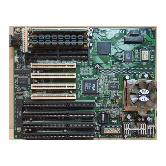
CHAPTER 1 INTRODUCTION This manual introduces how to configure the ATC-2000 mainboard for different environments. It's an overview of the layout and features of the mainboard, and also provides information for you to change the configuration or system environment. This manual is divided into two sections : PART ONE includes page A which contain layout diagram of the mainboard. -
Page 3: Check List Of The Packing
The mainboard comes securely packed in a durable box and shipping carton. If any of the above items are missed or damaged, please contact your supplier. Each mainboard containing: Q'TY Description Mainboard : ATC-2000. Diskette : Enhanced IDE driver (3.5"). Cable : Enhanced IDE connector. Cable : F.D.D. connector. -
Page 4: Chapter 2 Installation
CHAPTER 2 INSTALLATION 2-1 INSTALLATION PROCEDURE Before installing the computer, please prepare all components such as CPU, DRAM; peripherals such as hard disk drive, keyboard, CD-ROM drive; and accessories such as cables. Then, install the system as following 1. Plug CPU (w/ heat sink and cooling fan), DRAM modules in the mainboard. -
Page 5: Cpu Installation
2-2 CPU INSTALLATION ATC-2000 supports P54C and P55C types of CPUs up to 200MHz. For installation, please notice CPU pin 1 must align with the ZIF socket 7 Pin 1 location. In the 2-2-1 describes the jumper setting for each brand of CPU. If your CPU is not in the list of 2-2-1, please refer to 2-2-2 and 2-2-3 for installation. - Page 6 180MHz open close 60x3.0 200MHz close open 66x3.0 B. INTEL PENTIUM CPU (P55C) Besides CPU clock setting, for P55C (MMX) CPU you have to set JP10/ JP11/JP12/JP13 based on its CPU I/O voltage, and JP9 based on its core voltage. 3.52V3.3V2.9V2.8V*2.7V CPU Core Voltage JP91-23-45-67-89-10...
- Page 7 C. Cyrix 6x86 CPU Cyrix 6x86 ¡ JP9JP10JP11 1-21-21-2 INTERNAL CPU CLOCK Ext.x Frq. P120+ @ 100MHz close close 50x2.0 P150+ @ 120MHz open close 60x2.0 P166+ @ 133MHz close open 66x2.0 The bottom line of the mark on the processor contains a code 028 that (Cyrix logo) identifies the voltage level type.
- Page 8 INTERNAL CPU CLOCK Ext.x Frq. PR75ABR 75MHz close close 50x1.5 PR90ABQ 90MHz open close 60x1.5 PR100ABQ 100MHz close open 66x1.5 PR120ABQ 90MHz open close 60x1.5 PR133ABQ 100MHz close open 66x1.5 PR166ABQ close open 66x2.5 AMD-K5Ô PR100 AMD-K5-PR133ABQ 100MHz 2-2-2 CPU VOLTAGE SETTING JP9 is used to various CPU core voltage types.
-
Page 9: System Memory Installation
2-3 SYSTEM MEMORY INSTALLATION ATC-2000 provides four 72-pin SIM sockets for system memory expansion from 4MB to 256MB. These four SIMs are arranged to two banks, Bank0 (SIM 1, 2) and Bank1(SIM 3, 4), please refer to page A. Each... - Page 10 DRAM SIMMs among different banks; please plug EDO in Bank 0, if you only have 2 EDO modules. If you install more than 64MB DRAM on ATC-2000, and would like to get more than 64MB cacheable size function, you should plug one 16K8 (or 32K8) TAG RAM into U16A socket, and change BIOS value of ‘L2 Cache...
-
Page 11: Sram Installation
64MBx2 256MB 2-4 SRAM INSTALLATION ATC-2000 is built-in 256KB or 512KB Sync. Pipeline Burst SRAM on board and provides a Sync. SRAM module in COAST slot for further expansion. The maximum capacity is 512KB. ¡ System Memory Combinations Options ¡... -
Page 12: Other Jumpers And Connectors
¡ Upgrade Procedure : For upgrading your Sync. SRAM from 256KB to 512KB by using COAST Module, you should plug-in the KIT-256 module, then set JP1 to “open” ( disable the original TAG on board). You must use KIT-256 for upgrading your system to 512KB Sync. - Page 13 CN8 : Speaker, Keyboard Lock, Reset, SMI, Turbo LED, and IDE LED connectors. SPK : speaker KEYLOCK Speaker TB-LED IDE- KEYLOCK : keyboard lock switch and power LED connector Power LED + GND (power) Keylock GND (keylock) RST : Reset connector Reset Signal SMI : SMI lead SMI Signal...
- Page 14 IR1 : Infrared module connector. IRRX CN9 : Universal Serial Bus connector, this is IRTX used to connect USB devices through an optional dual head cable with a iron plane. (black) D0 - D1 - KB1 : 5-pin AT style compatible keyboard connector.
- Page 15 CN4 : this connector is used to connect floppy disk drive through cable. signal signal RWC- 20 STEP- reserved 22 Write Data FDEDIN 24 Write Gate Index- 26 Track 00- 10 Motor 28 Write Protect- EnableA- 12 Drive Sele.B- 30 Read Data- 14 Drive Sele.A- 32 Side 1 Sele.- 16 Motor...
-
Page 16: Ide Driver Installation
signal signal Reset IDE DDRQ0(1) Host Data 7 I/O Write- Host Data 8 Host Data 6 I/O Read- Host Data 9 Host Data 5 IORDY Host Data 10 Host Data 4 DDAK0-(1)- Host Data 11 Host Data 3 IRQ14* Host Data 12 IOCS16- Host Data 2 Addr 1... -
Page 17: Chapter 3 Award Bios Setup
ATC-2000 uses Flash ROM to make BIOS easier to be updated by the floppy disk-based program. and to committe Microsoft Windows 95 plug & play feature. -
Page 18: Award System Bios Configuration Setup
If the BIOS needs to be updated, it can be obtained on a diskette from your system supplier. The BIOS diskette includes 3 files: “awdflash.exe” -- BIOS update utility program “awdflash.doc” “(update BIOS filename with version number).rom” The update procedures are as following: 1. - Page 19 STANDARD CMOS SETUP INTEGRATED PERIPHERALS BIOS FEATURES SETUP PASSWORD SETTING CHIPSET FEATURES SETUP IDE HDD AUTO DETECTION POWER MANAGEMENT SETUP SAVE & EXIT SETUP PNP/PCI CONFIGURATION EXIT WITHOUT SAVING LOAD BIOS DEFAULTS ESC: Quit áâàß:Select Item F10: Save & Exit Setup (Shift) F2 : Change Color Time, Date, Hard Disk Type ..
- Page 20 from 0 to 23 (24-hour military - time) from 0 to 59 from 0 to 59 Primary Master These categories identify the types of 2 channels Primary Slave that have been installed in the computer. There Secondary Master are 45 predefined types and 4 user definable Secondary Slave types are for Enhanced IDE BIOS.
- Page 21 have to select the type in Setup. Halt On This category determines whether the computer will stop if an error is detectd during power up. No errors When the BIOS detects a non- fatal error the system will be stopped and you will be prompted All errors The system boot will not be...
- Page 22 This screen is a list of system configuration options. Some of them are defaults required by the mainboard's design, others depend on the features of your system. ROM PCI/ISA BIOS (2A59FA29) CMOS SETUP UTILITY AWARD SOFTWARE, INC. STANDARD CMOS SETUP INTEGRATED PERIPHERALS BIOS FEATURES SETUP PASSWORD SETTING...
- Page 23 Enabled Activates automatically when the system boots up causing a warning message to appear when anything attempts to access the boot sector or hard disk partition table. Disabled No warning message will appear when anything attempts to access the boot sector or hard disk partition table.
- Page 24 Boot Up System Selects the default system speed - the normal Speed operating speed at power up. Gate A20 This entry allows you to select how the gate Option A20 is handled. The gate A20 is a device used to address memory above 1 MB. Normal is keyboard;...
- Page 25 PCI/VGA It determines whether the MPEG ISA/VESA Palette Snoop VGA cards can work with PCI/VGA or not. Enabled When PCI/VGA working with MPEG ISA/VESA VGA Card Disabled When PCI/VGA not working with MPEG ISA/VESA VGA Card OS Select for This item allows you to access the memory DRAM >...
- Page 26 DRAM R/W Leadoff Timing : 7/6 Chipset NA# Asserted : Enabled Fast RAS# To CAS# Delay Pipeline Cache Timing : Faster DRAM Read Burst (EDO/FPM) : x333/x444 Passive Release : Enabled DRAM Write Burst Timing : x333 Delayed Transaction : Enabled Turbo Read Leadoff : Disabled DRAM Speculative Leadoff...
- Page 27 Video BIOS As with changing the system BIOS above, Cacheable enabling the Video BIOS cache will cause access to video BIOS addressed at C0000H to C7FFFH to be cached, if the cache controller is also enabled. 8 Bit I/O The recovery time is the length of time, measured Recovery Time in CPU clocks, which the system will delay after the completion of an I/O request.
- Page 28 PM Control by APM : Yes IRQ3 (COM 2) : OFF Video Off Method : V/H SYNC IRQ4 (COM 1) : OFF +Blank IRQ5 (LPT 2) : OFF Modem Use IRQ IRQ6 (Floppy Disk) : OFF IRQ7 (LPT 1) : OFF IRQ8 (RTC Alarm) : OFF Doze Mode...
- Page 29 The Following 4 modes are Green PC power saving function which are only user configuration when ‘User Defined’ power management has been selected. Doze Mode When enabled and after the set time of system inactivity, the CPU clock will run at slower speed while all other devices still operate at full speed Standby Mode When enabled and after the set time of system...
- Page 30 ESC: Quit áâàß:Select Item F10: Save & Exit Setup (Shift) F2 : Change Color IRQ Settings, Latency Timers, ..ROM PCI/ISA BIOS (2A59FA29) PNP/PCI CONFIGURATION AWARD SOFTWARE, INC. Resources Controlled by : Auto PCI IRQ Actived by : Level Reset Configuration Data : Disabled PCI IDE IRQ Map to : PCI-AUTO...
- Page 31 This section page includes all the items of IDE hard drive and Programmed Input/Output features. See also Section “Chipset FeaturesSetup”. ROM PCI/ISA BIOS (2A59FA29) CMOS SETUP UTILITY AWARD SOFTWARE, INC. STANDARD CMOS SETUP INTEGRATED PERIPHERALS BIOS FEATURES SETUP PASSWORD SETTING CHIPSET FEATURES SETUP IDE HDD AUTO DETECTION POWER MANAGEMENT SETUP...
- Page 32 primarily differ in timing. When Auto is selected, the BIOS will select the best available mode.
- Page 33 The last step is 'save and exit'. If you select this item and press 'Y', then these records will be saved in the CMOS memory on the mainboard. It will be checked every time when you turn your computer on. ROM PCI/ISA BIOS (2A59FA29) CMOS SETUP UTILITY AWARD SOFTWARE, INC.
- Page 34 SUPERVISOR PASSWORD / USER PASSWORD This allows you to set the password. the mainboard defaults password disabled. Enter/Change password : Enter the current password, at the prompt key-in your new password (up to eight alphanumeric characters), press <Enter>. At the next prompt, confirm the new password by typing it and press <Enter>...
- Page 35 ¡ Control Key Description ¡ UP ARROW ¡ Move to previous item DOWN ARROW ¡ Move to next item LEFT ARROW ¡ Move to the item in the left hand RIGHT ARROW ¡ Move to the item in the right hand Esc KEY Main Menu : Quit and not save...
- Page 36 If the mainboard doesn't function properly, please complete the following informationand return it to your system dealer. If further information is needed to describe the problem, please attach with separate sheets. Model No : ATC-2000 Date of Purchase : ______________ Serial No : ___________________...
Need help?
Do you have a question about the ATC-2000 and is the answer not in the manual?
Questions and answers