Table of Contents
Advertisement
Reproduction and distribution of this technical manual is
authorized for Government Purposes.
PN 3270465
February 2008, Rev. 1, 6/10
© 2008 - 2010 Fluke Corporation. All rights reserved. Printed in USA. Specifications are subject to change without notice.
All product names are trademarks of their respective companies.
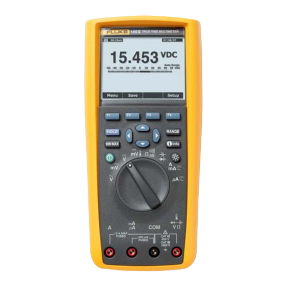
189II/AN
True-rms Digital Multimeter
Service Manual
Advertisement
Table of Contents

Related Manuals for Fluke 189II/AN


Summary of Contents for Fluke 189II/AN
- Page 1 Reproduction and distribution of this technical manual is authorized for Government Purposes. PN 3270465 February 2008, Rev. 1, 6/10 © 2008 - 2010 Fluke Corporation. All rights reserved. Printed in USA. Specifications are subject to change without notice. All product names are trademarks of their respective companies.
- Page 2 Fluke authorized resellers shall extend this warranty on new and unused products to end-user customers only but have no authority to extend a greater or different warranty on behalf of Fluke. Warranty support is available only if product is purchased through a Fluke authorized sales outlet or Buyer has paid the applicable international price.
-
Page 3: Table Of Contents
Table of Contents Title Page Introduction......................1 Contacting Fluke....................1 Precautions and Safety Information..............2 International Symbols ..................2 Safety Information ..................... 3 General Specifications ..................5 Detailed Specifications ..................5 AC Voltage Specifications ................6 AC Current Specifications................6 DC Voltage Specification................ - Page 4 189II/AN Service Manual Removing and Reinserting the Printed Circuit Assembly......13 Reassembling the Meter Case................ 14 Testing Fuses (F1 and F2) ................14 Replacing Fuses..................... 15 Replacing the Batteries.................. 15 Cleaning......................16 Performance Tests....................16 Factory Default....................17 Power LED Test .................... 17 Backlight Test....................
- Page 5 Page Symbols........................2 Required Equipment....................10 Temperature Test Input and Display ..............19 189II/AN Performance Test Steps ................. 19 Calibration Entry Soft Keys ................... 23 Softkey Functions during Calibration ..............25 Calibration Adjustment Steps for Firmware Version 1.00........26 Calibration Adjustment Steps for Firmware Version 1.10........28...
- Page 6 189II/AN Service Manual...
- Page 7 List of Figures Figure Title Page Fluke 189II/AN Block Diagram................12 Testing the Current Fuses..................15 Battery and Fuse Replacement................16 PCA Component Location ..................24 Calibration Adjustment Screenshot................ 24 Replacements Parts ....................32 Schematic Diagrams....................33...
- Page 8 189II/AN Service Manual...
-
Page 9: Introduction
Follow the standard practices for handling static sensitive devices. The information in this manual deals with the Fluke Model 189II/AN True-rms Digital Multimeter, (hereafter referred to as “the Meter”). Information provided includes: • Precautions and safety information •... -
Page 10: Precautions And Safety Information
Do not dispose of this product as Hazardous voltage present on input unsorted municipal waste. Go to of Meter. Fluke’s website for recycling information. -
Page 11: Safety Information
True-rms Digital Multimeter Safety Information Safety Information The Meter complies with: • ANSI/ISA 82.02.01 (61010-1) 2004 • UL 61010-1:2004 • CAN/CSA-C22.2 No. 61010-1-04 • IEC/EN 61010-1 2 Edition Pollution Degree 2 • EMC EN 61326-1 • Measurement Category III, 1000V, Pollution Degree 2 •... - Page 12 189II/AN Service Manual • When measuring current, turn off circuit power before connecting the Meter in the circuit. Remember to place the Meter in series with the circuit. • When making electrical connections, connect the common test lead before connecting the live test lead; when disconnecting, disconnect the live test lead before disconnecting the common test lead.
-
Page 13: General Specifications
General Specifications Maximum voltage between any Terminal and Earth Ground: 1000 V W Fuse Protection for mA or μA inputs..... 0.44 A (44/100 A, 440 mA), 1000 V FAST Fuse, Fluke specified part only W Fuse Protection for A input ......11 A, 1000 V FAST Fuse, Fluke specified part only Battery Type ............ -
Page 14: Ac Voltage Specifications
189II/AN Service Manual AC Voltage Specifications Accuracy Function Range Resolution 65 Hz to 10 20 to 45 Hz 45 to 65 Hz 10 to 20 kHz 20 to 100 kHz AC mV 50 mV 0.001 mV 1.5 % + 60 0.3 % + 25... -
Page 15: Dc Current Specifications
True-rms Digital Multimeter Detailed Specifications DC Current Specifications Accuracy AC over DC, DC over AC, AC + DC Function Range Resolution [1][3] 45 Hz to 1 20 to 100 kHz 20 to 45 Hz 1 to 20 kHz DC μA 500 μA 0.01 μA 0.075 % + 20... -
Page 16: Frequency Counter Specifications
189II/AN Service Manual Frequency Counter Specifications Function Range Resolution Accuracy Frequency 99.999 Hz 0.001 Hz 0.02 % + 5 (0.5 Hz to 999.99 kHz, pulse 999.99 Hz 0.01 Hz 0.005 % + 5 width >0.5 μs) 9.9999 kHz 0.0001 kHz 0.005 % + 5... -
Page 17: Input Characteristics
0.04 V/A Unpacking the Meter Open the Multimeter box. Inside will be found a 189II/AN Digital Multimeter, one set of test leads, a Product Manuals CD, a 189II/AN Users Manual, and a 189II/AN Service Manual. Remove the Meter from its plastic wrapping. -
Page 18: Hazardous Voltage
Capacitance Range: 5 nF Accuracy: ±0.55 % Temperature Range: 0 to 1000 °C Accuracy: 0.2 % Thermocouple Adapter K-type Fluke 80AK Accessory K-type Thermocouple wire K-type, mini-plug on both ends Serial Cable, Infrared Cable, Adapter, Fluke-Custom IRDA Optical to USB,2M Fluke P/N 2166275... -
Page 19: Theory Of Operation
True-rms Digital Multimeter Theory of Operation Theory of Operation The Meter includes the following major modules: Case, Display Module, Batteries, Shields, and the Printed Circuit Assembly (PCA). All the electrical processing is done on the PCA. There are four main sections of the PCA: analog signal conditioning and conversion, measurement processor, memory, and power supply. -
Page 20: Block Diagram
Figure 1. Fluke 189II/AN Block Diagram Testpoint Locations Not available for this Meter. Fault Isolation Techniques Not available for this Meter. If the Meter needs service, refer to the “Contacting Fluke” section. Wear Tolerance Not applicable for this Meter. Trouble Symptoms Not available for this Meter. - Page 21 A Message From Fluke Corporation Some semiconductors and custom IC's can be damaged by electrostatic discharge during handling. This notice explains how you can minimize the chances of destroying such devices 1. Knowing that there is a problem.
- Page 22 8. WHEN REMOVING PLUG-IN ASSEMBLIES 5. USE STATIC SHIELDING CONTAINERS FOR HANDLE ONLY BY NON-CONDUCTIVE HANDLING AND TRANSPORT. EDGES AND NEVER TOUCH OPEN EDGE CONNECTOR EXCEPT AT STATIC-FREE WORK STATION. PLACING SHORTING STRIPS ON EDGE CONNECTOR HELPS PROTECT INSTALLED S.S. DEVICES. 6.
-
Page 23: Basic Maintenance
True-rms Digital Multimeter Basic Maintenance Basic Maintenance XW Warning To avoid electrical shock or personal injury, remove the test leads and any input signals before opening the case or replacing the battery or fuses. To prevent damage or injury, install ONLY batteries or fuses specified for this product. Opening the Meter Case W Caution To avoid unintended circuit shorting, always place the... -
Page 24: Reassembling The Meter Case
189II/AN Service Manual Reassembling the Meter Case To reassemble the Meter case, do the following: 1. Verify the rotary switch knob is in the position (arrow on the rotary switch detent points straight up to the LCD). 2. Install the display bezel, LCD, and top shield into the top case. -
Page 25: Replacing Fuses
3. Remove either fuse by gently prying one end loose, then lifting the fuse out of the fuse contacts. 4. Install only Fluke specified replacement fuses with the amperage, voltage, and interrupt ratings shown in the replacement parts list (see Table 9). -
Page 26: Cleaning
189II/AN Service Manual 3. Replace the batteries, observing proper polarity. Replace the battery door and secure it by turning the fastener to the lock position. 11 A 0.44 A est32.eps Figure 3. Battery and Fuse Replacement Cleaning Periodically wipe the case with a damp cloth and mild detergent. Do not use abrasives, isopropyl alcohol, or solvents. -
Page 27: Factory Default
True-rms Digital Multimeter Performance Tests Factory Default Prior to completing the Performance tests reset the Meter to the factory defaults as follows: 1. Power the Meter on in any function. 2. Press F4 (Setup) and select Reset using arrow keys. 3. -
Page 28: Ir Port Verification
Append line feeds to incoming line ends Wrap lines that exceed terminal width 9. Enter the identification command <ID> followed by carriage return (Enter) 10. The Meter should return the response: FLUKE 189II, VX.XX, X, indicating the model, software version, and serial number. Note... -
Page 29: Accuracy Tests For Volts, Current, Ω, E, And G Test Functions
6. If the display reading falls outside of the Display Reading Limits shown in Table 4, the Meter does not meet specification and requires adjustment or repair. 7. Complete the remaining test steps for each function listed in Table 4. Table 4. 189II/AN Performance Test Steps Display Reading Frequency... - Page 30 189II/AN Service Manual Table 4. 189II/AN Performance Test Steps (cont.) Display Reading Frequency Step Function Range Input Level Lower Upper or Model Limit Limit DC mV 50.000 mV 50 mV 49.955 50.045 Discontinue REL Offsets DC mV 500.00 mV 500 mV 499.85...
- Page 31 True-rms Digital Multimeter Performance Tests Table 4. 189II/AN Performance Test Steps (cont.) Display Reading Frequency Step Function Range Input Level Lower Upper or Model Limit Limit 500.00 V 500 V 10 kHz 497.75 502.25 1000.0 V 1000 V 10 kHz 993.5...
-
Page 32: Calibration Adjustment
189II/AN Service Manual Table 4. 189II/AN Performance Test Steps (cont.) Display Reading Frequency Step Function Range Input Level Lower Upper or Model Limit Limit Connect 5520A, Auxiliary 20A output, to Meter’s A and COM Input Terminals 5.0000 A 1 kHz 4.9580... -
Page 33: Operation
True-rms Digital Multimeter Calibration Adjustment Operation Calibration adjustment is started by pressing the F1 [Setup] softkey, and then navigating to Calibration on the Setup menu. Note The Meter will not allow calibration a low battery condition. When Calibration is selected in the Setup menu, the F1-F4 softkeys function as shown in Table 5. -
Page 34: Calibration Adjustment Procedure
189II/AN Service Manual 4. Locate the PCA CAL key pad as shown in Figure 3. 5. Short the CAL key pad terminals to reset the password. When the password is reset, the Meter beeps to indicate that the action is complete. -
Page 35: Softkeys
True-rms Digital Multimeter Calibration Adjustment screen. • Calibration Step progress indicator. • Calibration status message. Usually blank, but displays one of the following messages when the given condition occurs: • Calibrating... is shown while measurements are being made after Next is pressed. -
Page 36: Power Cycle
189II/AN Service Manual If the measurement is not within calibration tolerance then after pressing NEXT, an error message will be shown and the calibration step will not proceed. The operator can adjust input signal if needed and attempt NEXT again. - Page 37 True-rms Digital Multimeter Calibration Adjustment Table 7. Calibration Adjustment Steps for Firmware Version 1.00 (cont.) Rotary Switch Settling Time Calibrating Time Step Source Value Position (seconds) (seconds) mV AC 0.0 V, 0 Hz 0.0 V, 0 Hz 5.0000 V, 60 Hz 5.0000 V, 65 kHz 50.000 V, 60 Hz 50.000 V, 100 kHz...
- Page 38 189II/AN Service Manual Table 7. Calibration Adjustment Steps for Firmware Version 1.00 (cont.) Rotary Switch Settling Time Calibrating Time Step Source Value Position (seconds) (seconds) Connect the 5520A in a 4-Wire configuration and select COMP 2-Wire 0 Ω, zcomp wire2...
- Page 39 True-rms Digital Multimeter Calibration Adjustment Table 8. Calibration Adjustment Steps for Firmware Version 1.10 (cont.) Rotary Switch Settling Time Calibrating Time Step Source Value Position (seconds) (seconds) 5.0 V, 55 Hz 5.0000 V, 60 kHz 50.0 V, 55 Hz 50.000 V, 100 kHz 500.0 V, 55 Hz 1000.0 V, 55 Hz 0.0 V, 0 Hz...
- Page 40 189II/AN Service Manual Table 8. Calibration Adjustment Steps for Firmware Version 1.10 (cont.) Rotary Switch Settling Time Calibrating Time Step Source Value Position (seconds) (seconds) mA DC 400.0 mA, 0 Hz mA AC 400.0 mA, 55 Hz 10.0 A, 0 Hz 10.0 A, 55 Hz...
-
Page 41: Parts
True-rms Digital Multimeter Parts Parts Table 9 lists the available replacement parts shown in Figure 6. Table 9. Replacement Parts Description Fluke Part No. Des. PCA MAIN Not Available SKIN, PADXFER 2798429 CASE TOP 2578178 CASE BOTTOM 2578184 MASK, LCD, PADXFER... - Page 42 189II/AN Service Manual MP16 MP30 MP12 MP42-44 MP49 XBT1 XBT2-3 H15-18 (4x) H7-14 (8x) MP45 MP46 H1-6 (6x) fet34.eps Figure 6. Replacements Parts...
-
Page 43: Schematic Diagrams
True-rms Digital Multimeter Schematic Diagrams Schematic Diagrams The schematic diagrams for the 189II/AN are shown in Figure 7. - Page 44 189II/AN Service Manual...
- Page 45 260MIL OPA2364 260MIL 10.0K XAF2 XBF2 50MIL .010 0.022U 0.022U NINV_X1 TP27 1.00M INPUT_JACK AVSS NINV_FB R270 AGND FLUKE-189II/AN-1001 65MIL 40.2K NINV_X5 (1 of 4) 260MIL AGND E131 C153 C154 R255 0.01U 0.01U SHIELD CONTACT 10.0K AGND AVSS AGND AGND...
- Page 46 RSOB DECODE MSP_TCK MSP_IRRXD TP34 RST* TP35 LP_COMP TP37 TP38 mVAC DVSS MSP_RSOB mVDC C/D (LZ) 0.1U 1.00M mA (VAC) FLUKE-189II/AN-1001 uA (mVAC) (2 of 4) AVSS LO (VDC) 56.2K 120K 100K 100K 182K 249K 280K 340K 30.1K 40.2K 49.9K AVSS AGND1 Figure 7.
- Page 47 4A6 3B3 TP13 MMBT3904 DVSS DVSS 10.0K 1.00K 3V_SW DVSS DVSS TP12 R133 10.0K FOR DEVELOPMENT ONLY FLUKE-189II/AN-1001 DVSS R128 10.0K DVSS DVSS (3 of 4) R124 10.0K R132 1.00K Figure 7. 189 II/AN System PCA - Digital Processor (cont)
- Page 48 QVDD3 QVSS 4.99K R100 DVSS QVDD4 QVSS 3V_SW 124K 4.7U QVSS AVDD1 +20V 3V_SW 3V_SW 3V_SW 3V_SW DVSS DVSS FLUKE-189II/AN-1001 0.1U 0.1U 0.1U 0.1U LCD_V4 LP324 (4 of 4) DVSS DVSS DVSS DVSS 4.75 R101 4.7U 124K DVSS DVSS DVSS...
Need help?
Do you have a question about the 189II/AN and is the answer not in the manual?
Questions and answers