
Subscribe to Our Youtube Channel
Related Manuals for Comelit AHPTZ110A


Summary of Contents for Comelit AHPTZ110A
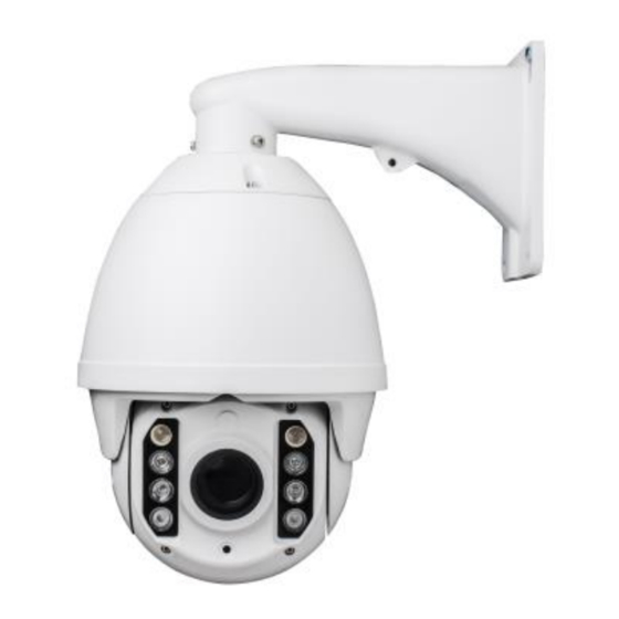
- Page 1 AHD PTZ CAMERA ART. AHPTZ110A – AHPTZ120A Please read this manual thoroughly before use and keep it for future reference...
-
Page 2: Table Of Contents
Contents Menu Index ..................................7 Menu Index .................................... 8 1 MENU SETTINGS ..................................9 1.1 SYSTEM INFORMATION ............................... 9 1.2 MOTION SETUP ................................. 10 1.2.2 DISPALY SETUP ..............................10 1.2.3 PATH SETUP ..............................11 1.2.4 CONTROL SETUP ............................. 14 1.2.5 ADDR SETTING ............................... 15 1.2.6 ALARM SETTING ............................. - Page 3 Cautions Non-professional do not disassemble the PTZ camera. Please read this manual carefully before operating. (This specification is subject to change without prior notice.) Cut the power supply off before operating the device to avoid damage caused by mis-operation. ...
- Page 4 System Requirements Control keyboard or other control device (with RS485 port) Monitor or other display device (with VIDEO IN port) 100÷240 VAC input, 24 VDC/1.5A output power adapte Installation environment Installation environment requirements Do not use in humid or high temperature environment, pay attention to keep good ventilation, avoid installation in the environment of severe vibration, as far as possible away from heating devices.
- Page 5 Wiring instructions: wire functions introduction from top to bottom Art. AHPTZ110A ① Video input ② Reset ③ Power supply ④ Alarm input ⑤ Alarm output ⑥ RS485 Art. AHPTZ120A ① Video input ② Reset ③ Power supply - ④ Power supply + ⑤...
- Page 6 Operation method The PTZ camera can be connected with keyboard device through RS485. The camera can be remotely controlled by moving up and down, moving left and right, and zooming lens. General functions 4.1 Up and down, left and right moving functions Up, down, left and right can be controlled by rocker.
-
Page 7: Menu Index
Menu Index PRESET SPEED TIME ADDRESS DISPLAY SETUP SWING SETUP PROTOCOL PELCO-D SYS- INFORMATION OFF BAUD RATE 2400 FUNC-DISPLAY NUMBER PT VERSION V1.10 COORDINATE SET SWING PRESET SETUP SPEED MASK SETUP AREA MAJOR ARC BACK CALL SWING EXIT CLEAR CURRENT BACK EXIT NEXT... -
Page 8: Menu Index
( a ) ( b ) IR SETTING IR LED AUTO NEAR IR LED MID IR LED FAR IR LED BACK EXIT FOCUS SETUP MODE AUTO ZOOM SPEED HIGH D-ZOOM D-ZOOM RATE BACK EXIT MAIN CAMERA MEUN WHITE BAL AUTO BACK LIGHT ESPOSURES SETUP MODE... -
Page 9: Menu Settings
1 MENU SETTINGS After the machine is installed and powered on, the PTZ camera will be self-checked, and the screen will display boot information, as shown in Figure 1-0-0. Display PTZ camera address ADDRESS COMMUNICATION PROTOCOL PELCO-D Display protocol recognition method BAUD RATE 9600 Display baud rate recognition method... -
Page 10: Motion Setup
1.2 MOTION SETUP In the menu of Figure 1-0-1, move the rocker up and down to point the cursor at motion setup, and then move the rocker to the right to enter motion setup menu, as shown in Figure 1-2-1. MOTION SETUP DISPLAY SETUP→... -
Page 11: Path Setup
EXIT: close the interface for setting privacy masks. ⑦ 1.2.3 PATH SETUP In Figure 1-2-1, move the rocker up and down so that the cursor points to the path setup, and then move the rocker to the right to enter the path setup menu. As shown in Figure 1-2-3. PATH SETUP SWING SETUP →... - Page 12 CRUISE SETTING: in Figure 1-2-3, move the rocker up and down so that the cursor points to the cruise setting, and then move ② the rocker to the right to enter the cruise setting menu, as shown in Figure 1-2-8. CRUISE SETTING NUMBER EDIT CRUISE...
- Page 13 PATTERN SETUP: in Figure 1-2-3, move the rocker up and down to point the cursor at pattern setup, and then move the rocker ③ to the right to enter the pattern setup menu, as shown in Figure 1-2-10. PATTERN SETUP NUMBER SET PATTERN CALL PATTERN...
-
Page 14: Control Setup
1.2.4 CONTROL SETUP In Figure 1-2-1, move the rocker up and down to point the cursor at the control setup, and then move the rocker to the right to enter the control setup menu. As shown in figure 1- 2-14. CONTROL SETUP POWER UP ACTION (Figure 1-2-15) -
Page 15: Addr Setting
TIME: set idle action time, the time can be selected: 1-255 mins. The default idle time is one minute. ACTION TYPE: this option is to set the type of idle action. Presets, linear scan, cruise scan, pattern scan, group scan, continuous scan and interval scan optional, default is no action. -
Page 16: Ir Setting
ALARM SETTING NUMBER ALARM ACT ACTION ALARM ACT ACRTON (Figure 1-2-19) → INPUT TYPE CLOSE OUTPUT TYPE CLOSE DWELL TIME ACTIVATE AUS CLEAR CURRENT BCAK EXIT Figure1-2-6 NUMBER: default is on 1 ① ② ALARM ACT ACTION: in Figure 1-2-6 move the rocker up and down to make the cursor point to the alarm act action, and then move the rocker to the right to enter the alarm act action menu. -
Page 17: Camera Setup
IR SETTING IR LED AUTO NERA IR LED ---- MID IR LED ---- FAR IR LED BACK EXIT Figure 1-2-7 IR LED: auto, manual and off optional, default is auto. When set to auto, the PTZ camera can automatically turn on or off the ①... -
Page 18: White Bal
Figure 1-3-1 1.3.2 WHITE BAL WHITE BAL: auto tracking white balance, manual, auto white balance →AUTO, outdoor, indoor, ATW Option Description: ① AUTO: the camera automatically sets the value of camera white balance according to the current environment. ② ATW: in the case of complex light environment, a white paper is placed in front of the lens, and the image is displayed on a full screen. -
Page 19: Esposure
III MANUAL: press [OPEN] to set zoom focus. The focus mode of the camera is manual and requires Focus Command focusing. ② Z OOM SPEED :high,low,middle optional d efault is high. Option Description: Manual: press [OPEN] to initialize the lens once. Auto: press [OPEN] to enter and set lens initialization cycle, the cycle can be selected 1-7 days. -
Page 20: Reset
Figure 1-3-4 ① DAY-NIGHT: auto, color, B/W optional, default is auto Option Description: Auto: the camera determine the color and B/W state according to its environment. II Color: the camera set to color state III B/W: the camera is set to black and white state. In Figure 1-3-4 ,... -
Page 21: Preset Lock
1.4.1 PRESET LOCK The preset point lock can be turned on or off , default is off. When the preset point lock is set to open, the preset point cannot be set by keyboard. When the preset point is open, the preset point is set by keyboard, and the screen will prompt "the preset point lock on". -
Page 22: Edit Password
1.4.3 EDIT PASSWORD In the menu of Figure 1-4-1, move the rocker up and down to point the cursor at the edit password and then move the rocker to the right to enter the edit password menu, as shown in Figure 1-4-2. FIRET STEP PUT OLD PASSWORD BACK SSSSSSSS NXST... -
Page 23: Reboot System
③ In Figure 1-5-2, move the rocker up and down so that the cursor points to clear all swings, and then move the rocker to the right to delete all swings. ④ In Figure 1-5-2, move the rocker up and down so that the cursor points to clear all cruises, and then move the rocker to the right to delete all cruises.
Need help?
Do you have a question about the AHPTZ110A and is the answer not in the manual?
Questions and answers