Table of Contents
Advertisement
Quick Links
Advertisement
Table of Contents

Related Manuals for Minebea Intec PR 6130/64Sa


Summary of Contents for Minebea Intec PR 6130/64Sa
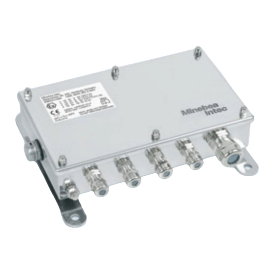
- Page 1 Installation Manual Cable Junction Box PR 6130/64Sa Translation of the Original Installation Manual 9499 053 06400 Edition 3.8.0 07/21/2021 Minebea Intec GmbH, Meiendorfer Str. 205 A, 22145 Hamburg, Germany Phone: +49.40.67960.303 Fax: +49.40.67960.383...
- Page 2 Any information in this document is subject to change without notice and does not represent a commitment on the part of Minebea Intec unless legally prescribed. This product should only be operated/installed by trained and qualified personnel. In correspondence concerning this product, the type, name, and release number/serial number as well as all license numbers relating to the product have to be cited.
-
Page 3: Table Of Contents
Cable Junction Box PR 6130/64Sa Table of contents Table of contents Introduction............................3 Read the manual................................. 3 This is what operating instructions look like ......................3 This is what lists look like............................3 This is what menu items and softkeys look like..................... 3 This is what the safety instructions look like...................... - Page 4 Cable Junction Box PR 6130/64Sa Table of contents Repairs..................................20 Soldering work ................................20 Cleaning ..................................20 Disposal ..............................21 Certificates/safety instructions/control drawing/Ex design .............. 22 DEKRA 13ATEX0133X ............................... 23 IECEx DEK 13.0042X..............................26 MEU17042...................................31 FM17CA0156X................................37 FM17US0275X ................................41 RU С-DE.МЮ62.В.05021............................45 36931-751-16 ................................48 36931-751-08 ................................51 36931-751-07................................53...
-
Page 5: Introduction
1 Introduction Cable Junction Box PR 6130/64Sa Introduction Read the manual Please read this manual carefully and completely before using the product. This manual is part of the product. Keep it in a safe and easily accessible location. This is what operating instructions look like 1. -
Page 6: Hotline
Cable Junction Box PR 6130/64Sa 1 Introduction NOTICE Warning of damage to property and/or the environment. NOTICE indicates that damage to property and/or the environment may occur if appropriate safety measures are not observed. Take the corresponding safety precautions. Note: User tips, useful information, and notes. -
Page 7: Safety Instructions
2 Safety instructions Cable Junction Box PR 6130/64Sa Safety instructions General notes CAUTION Warning of personal injury. The product was in perfect condition with regard to safety features when it left the factory. To maintain this condition and to ensure safe operation, the user must follow the instructions and observe the warnings in this manual. -
Page 8: Initial Inspection
General information Repairs are subject to inspection and must be carried out at Minebea Intec. In case of defect or malfunction, please contact your local Minebea Intec dealer or service center for repair. When returning the device for repair, please include a precise and complete description of the problem. -
Page 9: Specifications
3 Specifications Cable Junction Box PR 6130/64Sa Specifications Equipment supplied Description Cover Box incl. electronics Cable gland M20 Ex-zone locking pin 6 mm (3×) Cable gland M12 (4×) Gasket Pressure compensation element Jumpers for corner correction resistors Minebea Intec EN-7... -
Page 10: Technical Data
Cable Junction Box PR 6130/64Sa 3 Specifications Description The following items are not shown: Drilling template Quick guide Safety instructions for cable junction boxes to be used in potentially explosive atmospheres Technical Data Protection classes in compliance with IEC 529 or DIN EN 60529... -
Page 11: Electromagnetic Compatibility (Emc)
3 Specifications Cable Junction Box PR 6130/64Sa Electromagnetic Compatibility (EMC) All data in compliance EN 61326 industrial section Housing High frequency electromagnetic fields EN 61000-4-3 10 V/m (80…3000 MHz) Electrostatic discharge (ESD) EN 61000-4-2 6/8 kV Signal and control Fast transients (burst) - Page 12 Cable Junction Box PR 6130/64Sa 3 Specifications Zone Marking Certificate No. IS CL I, II, III, DIV 1, GP A,B,C,D,E,F,G T4 - FM17US0275X 36931-751-07; Type 4X, IP6x NI CL I, II, III, DIV 2, GP A,B,C,D,E,F,G T4; Type 4X, IP6x S CL II, DIV 2, GP E,F,G / T4;...
-
Page 13: Dimensions
3 Specifications Cable Junction Box PR 6130/64Sa Dimensions all dimensions in mm Minebea Intec EN-11... -
Page 14: Installation And Connection Information
Cable Junction Box PR 6130/64Sa 4 Installation and connection information 4 Installation and connection information General information Note: When used in protection class "Ex nA" (non-sparking), a transient protective device must be set to a level that does not exceed 140% of the peak voltage of 85 V. -
Page 15: Terminals And Jumpers
4 Installation and connection information Cable Junction Box PR 6130/64Sa Terminals and jumpers Signal + green Terminal contacts + measuring voltage (load cells) 1–4 Terminal contact + measuring voltage (connection cable) Signal - gray Terminal contacts - measuring voltage (load cells) 1–4... -
Page 16: 4.4 Connecting Load Cells With A 4-Wire Cable
Cable Junction Box PR 6130/64Sa 4 Installation and connection information Screen yellow Terminal contacts Screen (load cells) 1–4 Terminal contact Screen (connection cable) Jumper Connects the load cell supply line to the sense line. Both jumpers must be opened Jumper when 6-wire load cell cables are used. -
Page 17: Cable Connections
5 Cable connections Cable Junction Box PR 6130/64Sa Cable connections General information In order to use the junction boxes for load cells with 6-wire cables, jumpers J1 and J2 must be opened; see Chapter 4.3. Cable entry must be from below. -
Page 18: Cable Connections
Cable Junction Box PR 6130/64Sa 5 Cable connections Cable connections Note: All components are only shown schematically. Color code black blue green gray white Connection example EN-16 Minebea Intec... -
Page 19: Equipotential Bonding Conductor
5 Cable connections Cable Junction Box PR 6130/64Sa Equipotential bonding conductor NOTICE It is especially important that the ground is connected correctly to the components and the cable junction box. You must also ground the device separately and ensure the power supply is properly shielded against the effects of lightning. -
Page 20: Electronic Corner Correction
Electronic corner correction 5.5.1 General information Minebea Intec load cells are produced according to high quality standards and have precisely adjusted output values. Nonetheless, mechanical imbalances can cause impermissible corner load errors to arise, which will need to be offset by soldering in resistors.
Need help?
Do you have a question about the PR 6130/64Sa and is the answer not in the manual?
Questions and answers