Table of Contents

Subscribe to Our Youtube Channel
Related Manuals for Minebea Intec PR 6130/34Sa


Summary of Contents for Minebea Intec PR 6130/34Sa
- Page 1 Installation Manual Cable Junction Box PR 6130/34Sa Translation of the Original Installation Manual 9499 053 03400 Edition 3.6.0 07/21/2021 Minebea Intec GmbH, Meiendorfer Str. 205 A, 22145 Hamburg, Germany Phone: +49.40.67960.303 Fax: +49.40.67960.383...
- Page 2 Any information in this document is subject to change without notice and does not represent a commitment on the part of Minebea Intec unless legally prescribed. This product should only be operated/installed by trained and qualified personnel. In correspondence concerning this product, the type, name, and release number/serial number as well as all license numbers relating to the product have to be cited.
-
Page 3: Table Of Contents
Cable Junction Box PR 6130/34Sa Table of contents Table of contents Introduction............................3 Read the manual................................. 3 This is what operating instructions look like ......................3 This is what lists look like............................3 This is what menu items and softkeys look like..................... 3 This is what the safety instructions look like...................... - Page 4 Cable Junction Box PR 6130/34Sa Table of contents Soldering work ................................19 Cleaning ..................................19 Disposal .............................20 Certificates ............................21 MEU17042..................................22 EN-2 Minebea Intec...
-
Page 5: Introduction
1 Introduction Cable Junction Box PR 6130/34Sa Introduction Read the manual Please read this manual carefully and completely before using the product. This manual is part of the product. Keep it in a safe and easily accessible location. This is what operating instructions look like 1. -
Page 6: Hotline
Cable Junction Box PR 6130/34Sa 1 Introduction NOTICE Warning of damage to property and/or the environment. NOTICE indicates that damage to property and/or the environment may occur if appropriate safety measures are not observed. Take the corresponding safety precautions. Note: User tips, useful information, and notes. -
Page 7: Safety Instructions
2 Safety instructions Cable Junction Box PR 6130/34Sa Safety instructions General notes CAUTION Warning of personal injury. The product was in perfect condition with regard to safety features when it left the factory. To maintain this condition and to ensure safe operation, the user must follow the instructions and observe the warnings in this manual. -
Page 8: Initial Inspection
General information Repairs are subject to inspection and must be carried out at Minebea Intec. In case of defect or malfunction, please contact your local Minebea Intec dealer or service center for repair. When returning the device for repair, please include a precise and complete description of the problem. -
Page 9: Specifications
3 Specifications Cable Junction Box PR 6130/34Sa Specifications Equipment supplied Description Cover Box incl. electronics Sealing ring for M20 Cable gland M20 Reduction sealing ring M20 (for ≤8 mm) Locking pin 6 mm (3×) Cable gland M12 (4×) Sealing ring for M12 (4×) -
Page 10: Technical Data
Cable Junction Box PR 6130/34Sa 3 Specifications Description The following items are not shown: Drilling template Quick guide Technical Data Protection classes in compliance with IEC 529 or DIN EN 60529 IP66/IP68/P69: Dust-proof and leak-proof against water, with harmful effects when immersed, (0.5 m water depth, 1,000 h) and water jets (high pressure and temperature). -
Page 11: Electromagnetic Compatibility (Emc)
3 Specifications Cable Junction Box PR 6130/34Sa Electromagnetic Compatibility (EMC) All data in compliance EN 61326 industrial section Housing High frequency electromagnetic fields EN 61000-4-3 10 V/m (80…3000 MHz) Electrostatic discharge (ESD) EN 61000-4-2 6/8 kV Signal and control Fast transients (burst) -
Page 12: Dimensions
Cable Junction Box PR 6130/34Sa 3 Specifications Dimensions all dimensions in mm EN-10 Minebea Intec... -
Page 13: Installation And Connection Information
4 Installation and connection information Cable Junction Box PR 6130/34Sa 4 Installation and connection information General information Only use the cable glands provided by the manufacturer. Install the junction box so that the cable glands are on the bottom. Do not open the junction box when connected to the voltage supply. -
Page 14: Connecting Load Cells With A 4-Wire Cable
Cable Junction Box PR 6130/34Sa 4 Installation and connection information Sense - black Terminal contacts - sense (load cells) 1–4 Terminal contact - sense (connection cable) Sense + white Terminal contacts + sense (load cells) 1–4 Terminal contact + sense (connection cable) -
Page 15: Cable Gland
4 Installation and connection information Cable Junction Box PR 6130/34Sa Cable gland The cable glands each have one sealing ring. The cables have to be fed into the device via glands to ensure leak-tightness. The following cable diameters are suitable: 8…13 mm for gland M20 and 3…6 mm for cable gland M12. -
Page 16: Cable Connections
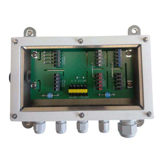
Cable Junction Box PR 6130/34Sa 5 Cable connections Cable connections General information In order to use the junction boxes for load cells with 6-wire cables, jumpers J1 and J2 must be opened; see Chapter 4.2. Cable entry must be from below. - Page 17 5 Cable connections Cable Junction Box PR 6130/34Sa Connection example Minebea Intec EN-15...
-
Page 18: Equipotential Bonding Conductor
Cable Junction Box PR 6130/34Sa 5 Cable connections Equipotential bonding conductor NOTICE It is especially important that the ground is connected correctly to the components and the cable junction box. You must also ground the device separately and ensure the power supply is properly shielded against the effects of lightning. -
Page 19: Electronic Corner Correction
Electronic corner correction 5.5.1 General information Minebea Intec load cells are produced according to high quality standards and have precisely adjusted output values. Nonetheless, mechanical imbalances can cause impermissible corner load errors to arise, which will need to be offset by soldering in resistors. - Page 20 Cable Junction Box PR 6130/34Sa 5 Cable connections The following steps are necessary to minimize corner load errors: Select the load cell with the lowest displayed load as the reference cell. 2. In the junction box, remove the jumper from the relevant measurement cable (Signal +) and solder in a resistor according to the abovementioned formula (in the example 4.38 Ω).
-
Page 21: Maintenance/Repairs/Soldering Work/Cleaning
Repairs Repairs are subject to inspection and must be carried out at Minebea Intec. In case of defect or malfunction, please contact your local Minebea Intec dealer or service center for repair. When returning the device for repair, please include a precise and complete description of the problem. -
Page 22: Disposal
Cable Junction Box PR 6130/34Sa 7 Disposal Disposal If the packaging is no longer required, please take it to your local waste disposal facility and/or a reputable disposal company or collection point. The packaging largely consists of environmentally friendly materials which can be used as secondary raw materials. -
Page 23: Certificates
8 Certificates Cable Junction Box PR 6130/34Sa Certificates Ser. no. Description Document no. see Chapter EU-Declaration of Conformity MEU17042 Minebea Intec EN-21... -
Page 24: Meu17042
Cable Junction Box PR 6130/34Sa 8 Certificates MEU17042 EN-22 Minebea Intec... - Page 25 8 Certificates Cable Junction Box PR 6130/34Sa Minebea Intec EN-23...
- Page 26 Cable Junction Box PR 6130/34Sa 8 Certificates EN-24 Minebea Intec...
- Page 27 8 Certificates Cable Junction Box PR 6130/34Sa Minebea Intec EN-25...
- Page 28 Cable Junction Box PR 6130/34Sa 8 Certificates EN-26 Minebea Intec...
- Page 29 8 Certificates Cable Junction Box PR 6130/34Sa Minebea Intec EN-27...
- Page 30 Published by Minebea Intec GmbH | Meiendorfer Strasse 205 A | 22145 Hamburg, Germany Phone: +49.40.67960.303 | Email: info@minebea-intec.com www.minebea-intec.com...
Need help?
Do you have a question about the PR 6130/34Sa and is the answer not in the manual?
Questions and answers