Table of Contents
Advertisement
Available languages
Available languages
Quick Links
Advertisement
Chapters
Table of Contents

Related Manuals for Minebea Intec PR 6130/68S


Summary of Contents for Minebea Intec PR 6130/68S
- Page 1 Installation Manual Cable Junction Box PR 6130/68S Translation of the Original Installation Manual 9499 053 06801 Edition 3.1.1 08/24/2017 Minebea Intec GmbH, Meiendorfer Str. 205 A, 22145 Hamburg, Germany Phone: +49.40.67960.303 Fax: +49.40.67960.383...
- Page 2 Any information in this document is subject to change without notice and does not represent a commitment on the part of Minebea Intec unless legally prescribed. This product should be operated only by trained and qualified personnel. In correspondence concerning this product, the type, designation and version number as well as all license numbers relating to the product have to be cited.
-
Page 3: Table Of Contents
Cable Junction Box PR 6130/68S Table of contents Table of contents Introduction............................3 Read the manual................................. 3 This is what instructions look like..........................3 This is what lists look like............................3 This is what menus and soft keys look like ......................3 This is what safety instructions look like......................... - Page 4 Cable Junction Box PR 6130/68S Table of contents Cleaning ..................................20 Disposal ..............................21 Appendix ............................22 Minebea Intec EN-2...
-
Page 5: Introduction
1 Introduction Cable Junction Box PR 6130/68S Introduction Read the manual Please read this manual carefully and completely before using the product. This manual is part of the product. Keep it in a safe and easily accessible location. This is what instructions look like 1. -
Page 6: Hotline
Cable Junction Box PR 6130/68S 1 Introduction NOTICE Warning of property and/or environmental damage. ATTENTION indicates that damage to property and/or the environment may occur if appropriate safety measures are not observed. Take appropriate safety measures. Note: User tips, useful information and notes. -
Page 7: Safety Instructions
2 Safety instructions Cable Junction Box PR 6130/68S Safety instructions General notes CAUTION Warning of personal injury. The product was in perfect condition with regard to safety features when it left the factory. To maintain this condition and to ensure safe operation, the user must follow the instructions and observe the warnings in this manual. -
Page 8: Incoming Goods Inspection
General information Repairs are subject to inspection and must be carried out at Minebea Intec. In case of defect or malfunction, please contact your local Minebea Intec dealer or service center for repair. When returning the device for repair, please include a precise and complete description of the problem. -
Page 9: Specifications
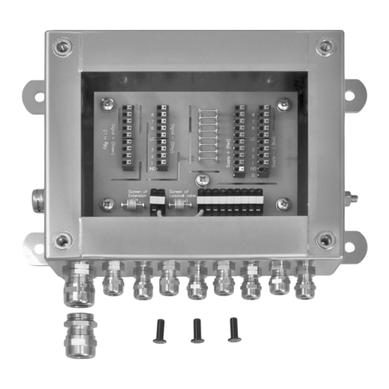
3 Specifications Cable Junction Box PR 6130/68S Specifications Equipment supplied Description Cover Box incl. electronics Cable gland M12 (8×) Cable gland M20 (9–13 mm) Ex-zone locking pin 6 mm (3×) Cable gland M20 (6–12 mm) Pressure compensation element EN-7 Minebea Intec... -
Page 10: Technical Data
Cable Junction Box PR 6130/68S 3 Specifications Description Jumpers for corner correction impedances The following items are not shown: Drilling template Installation manual 9499 053 06801 Certificates Technical Data Protection classes per DIN EN 60529 IP68, IP69: Dust-proof and leak-proof against water, with harmful effects when immersed, (1.5 m water depth, 10,000 h) -
Page 11: Electromagnetic Compatibility (Emc)
3 Specifications Cable Junction Box PR 6130/68S Electromagnetic Compatibility (EMC) All data corresponds to EN 61326 industrial section Housing High frequency electromagnetic fields EN 61000-4-3 10 V/m (80…3000 MHz) Electrostatic discharge (ESD) EN 61000-4-2 6/8 kV Signal and control Fast transients (burst) - Page 12 Cable Junction Box PR 6130/68S 3 Specifications The relevant protection class must be indi- cated on the rating plate! Note: The marking for ATEX is shown as an ex- ample. Note: See also Chapter 8. Minebea Intec EN-10...
-
Page 13: Dimensions
3 Specifications Cable Junction Box PR 6130/68S Dimensions all dimensions in mm EN-11 Minebea Intec... -
Page 14: Installation And Connection Information
Cable Junction Box PR 6130/68S 4 Installation and connection information 4 Installation and connection information General information Note: When used in protection class "Ex nA" (non-sparking), a transient protective device must be set to a level that does not exceed 140% of the peak voltage of 85 V. -
Page 15: Terminals And Jumpers
4 Installation and connection information Cable Junction Box PR 6130/68S Terminals and jumpers Signal + green Terminal contacts + measuring voltage (load cells) 1…8 Terminal contact + measuring voltage (connection cable) Signal - gray Terminal contacts - measuring voltage (load cells) 1…8... -
Page 16: 4.4 Cable Gland
Cable Junction Box PR 6130/68S 4 Installation and connection information 4.4 Cable gland The cables have to be fed into the device via glands to ensure leak-tightness. The following cable diameters are suitable: 6…12 mm for gland M20 and 3…6 mm for cable gland M12. -
Page 17: Cable Connections
5 Cable connections Cable Junction Box PR 6130/68S Cable connections General information Cable entry must be from below. Fit the wires and screen of the connection cable with wire end ferrules. This is not necessary for the load cell cables. - Page 18 Cable Junction Box PR 6130/68S 5 Cable connections Color code black blue green gray white Minebea Intec EN-16...
-
Page 19: Equipotential Bonding Conductor
5 Cable connections Cable Junction Box PR 6130/68S Equipotential bonding conductor NOTICE It is especially important that the ground is connected correctly to the components and the cable junction box. You must also ground the device separately and ensure the power supply is properly shielded against the effects of lightning. -
Page 20: Electronic Corner Correction
Electronic corner correction 5.5.1 General information Load cells from Minebea Intec are manufactured according to high quality standards and have very precisely balanced output values. Nevertheless, mechanical imbalances may cause impermissibly large corner load errors, which must be compensated for by soldering in resistors. - Page 21 5 Cable connections Cable Junction Box PR 6130/68S Display 12,052 kg 1080 Ω (see load cell installation manual) 4.68 Ω Calculated resistivity In the junction box, remove the wire jumper for the corresponding supply line (Supply +) and solder in a resistor of 4.68 Ω.
-
Page 22: Maintenance/Repairs/Soldering Work/Cleaning
Repairs Repairs are subject to inspection and must be carried out at Minebea Intec. In case of defect or malfunction, please contact your local Minebea Intec dealer or service center for repair. When returning the device for repair, please include a precise and complete description of the problem. - Page 23 7 Disposal Cable Junction Box PR 6130/68S Disposal If the packaging is no longer required, please take it to your local waste disposal facility and/or a reputable disposal company or collection point. The packaging largely consists of environmentally friendly materials which can be used as secondary raw materials.
- Page 24 Cable Junction Box PR 6130/68S 8 Appendix Appendix Ser. no. Description Document no. Safety instructions 36931-751-16 EC type examination certificate DEKRA 13ATEX0133 X IECEx declaration of conformity IECEx DEK 13.0042 X TR CU 012 certificate RU С-DE.МЮ62.В.05021 Minebea Intec EN-22...
- Page 26 Published by Minebea Intec GmbH | Meiendorfer Strasse 205 A | 22145 Hamburg, Germany Phone: +49.40.67960.303 | Email: info@minebea-intec.com www.minebea-intec.com...
- Page 27 Installationshandbuch Kabelverbindungskasten PR 6130/68S Originalinstallationshandbuch 9499 053 06801 Ausgabe 3.1.1 24.08.2017 Minebea Intec GmbH, Meiendorfer Str. 205 A, 22145 Hamburg, Deutschland Tel.: +49.40.67960.303 Fax: +49.40.67960.383...
- Page 28 Vorwort Unbedingt beachten! Alle Angaben in diesem Dokument sind - soweit nicht gesetzlich vorgegeben - unverbindlich für Minebea Intec und stehen unter Änderungsvorbehalt. Die Bedienung des Produktes darf nur von geschultem, fach- und sachkundigem Personal durchgeführt werden. Bei Schriftwechsel über dieses Produkt bitte Typ, Bezeichnung und Versionsnummer sowie alle mit dem Produkt in Zusammenhang stehenden Lizenznummern angeben.
- Page 29 Kabelverbindungskasten PR 6130/68S Inhaltsverzeichnis Inhaltsverzeichnis Einleitung ............................3 Lesen Sie das Handbuch............................3 So sehen Handlungsanweisungen aus........................3 So sehen Listen aus ..............................3 So sehen Menüs und Softkeys aus........................... 3 So sehen Sicherheitshinweise aus ........................... 3 Hotline ..................................4 Sicherheitshinweise ..........................
- Page 30 Kabelverbindungskasten PR 6130/68S Inhaltsverzeichnis Reinigung..................................21 Entsorgung ............................22 Anhang .............................. 23 Minebea Intec DE-2...
-
Page 31: Einleitung
1 Einleitung Kabelverbindungskasten PR 6130/68S Einleitung Lesen Sie das Handbuch Lesen Sie das Handbuch aufmerksam und vollständig durch, bevor Sie mit dem Produkt arbeiten. Dieses Handbuch ist Teil des Produktes. Bewahren Sie es gut erreichbar und sicher auf. So sehen Handlungsanweisungen aus 1. -
Page 32: Hotline
Kabelverbindungskasten PR 6130/68S 1 Einleitung VORSICHT Warnung vor Personenschäden. VORSICHT vor möglicher eintretender Situation mit leichten, reversiblen Verletzungen als Folge, wenn die entsprechenden Vorsichtsmaßnahmen nicht getroffen werden. Entsprechende Vorsichtsmaßnahmen ergreifen. ACHTUNG Warnung vor Sach- und/oder Umweltschäden. ACHTUNG vor möglicher eintretender Situation mit Sach- und/oder Umweltschäden als Folge, wenn die entsprechenden Vorsichtsmaßnahmen nicht getroffen werden. -
Page 33: Sicherheitshinweise
2 Sicherheitshinweise Kabelverbindungskasten PR 6130/68S Sicherheitshinweise Allgemeine Hinweise VORSICHT Warnung vor Personenschäden. Das Produkt hat das Werk in sicherheitstechnisch einwandfreiem Zustand verlassen. Um diesen Zustand zu erhalten und einen gefahrlosen Betrieb sicherzustellen, muss der Anwender die Hinweise und Warnvermerke dieser Dokumentation befolgen. -
Page 34: Wareneingangskontrolle
Reparatur und Wartung 2.5.1 Allgemeine Hinweise Reparaturen sind prüfpflichtig und können nur bei Minebea Intec durchgeführt werden. Bei einem Defekt oder einer Funktionsstörung bitte an die lokale Vertretung von Minebea Intec wenden, um Reparaturmaßnahmen einzuleiten. Das Gerät muss mit exakter und kompletter Fehlerbeschreibung zur Reparatur eingeschickt werden. -
Page 35: Spezifikation
3 Spezifikation Kabelverbindungskasten PR 6130/68S Spezifikation Lieferumfang Pos. Bezeichnung Deckel Kasten inkl. Elektronik Kabelverschraubung M12 (8×) Kabelverschraubung M20 (9…13 mm) Ex-Verschlussstift 6 mm (3×) Kabelverschraubung M20 (6…12 mm) Druckausgleichselement DE-7 Minebea Intec... -
Page 36: Technische Daten
Kabelverbindungskasten PR 6130/68S 3 Spezifikation Pos. Bezeichnung Brücken für die Eckenabgleichwiderstände Folgende Positionen sind ohne Abbildung: Bohrschablone Installationshandbuch 9499 053 06801 Zertifikate Technische Daten Schutzarten gemäß DIN EN 60529 IP68, IP69: Staubdicht und geschützt gegen Eindringen von Was- ser mit schädlichen Wirkungen bei Eintauchen (1,5 m Wassertiefe, 10.000 h) und Strahlwasser (hoher Druck... -
Page 37: Elektromagnetische Verträglichkeit (Emv)
3 Spezifikation Kabelverbindungskasten PR 6130/68S Elektromagnetische Verträglichkeit (EMV) Alle Daten in Übereinstimmung mit EN 61326 Industriebereich Gehäuse Hochfrequente elektromagnetische EN 61000-4-3 10 V/m Felder (80…3000 MHz) Elektrostatische Entladung (ESD) EN 61000-4-2 6/8 kV Signal- und Steuer- Schnelle transiente Störgrößen (Burst) EN 61000-4-4... - Page 38 Kabelverbindungskasten PR 6130/68S 3 Spezifikation Die zutreffende Schutzart muss auf diesem Typenschild angekreuzt werden! Hinweis: Die Kennzeichnung ist beispielhaft für ATEX abgebildet. Hinweis: Siehe auch Kapitel 8. Minebea Intec DE-10...
-
Page 39: Abmessungen
3 Spezifikation Kabelverbindungskasten PR 6130/68S Abmessungen alle Abmessungen in mm DE-11 Minebea Intec... -
Page 40: Montage- Und Anschlusshinweise
Kabelverbindungskasten PR 6130/68S 4 Montage- und Anschlusshinweise 4 Montage- und Anschlusshinweise Allgemeine Hinweise Hinweis: Bei Anwendung in Schutzart "Ex nA" nicht funkend muss eine transiente Schutzvorrichtung auf eine Stufe festgelegt werden, die 140% des Werts der Spitzenspannung von 85 V nicht überschreitet. -
Page 41: Anschlussklemmen Und Brücken
4 Montage- und Anschlusshinweise Kabelverbindungskasten PR 6130/68S Anschlussklemmen und Brücken Signal + grün Klemmkontakte + Messspannung Wägezellen 1…8 Klemmkontakt IND + Messspannung Verbindungskabel Signal - grau Klemmkontakte - Messspannung Wägezellen 1…8 Klemmkontakt IND - Messspannung Verbindungskabel Supply + Klemmkontakte + Speisespannung Wägezellen 1…8... - Page 42 Kabelverbindungskasten PR 6130/68S 4 Montage- und Anschlusshinweise Die Kabeladern werden im Gerät auf die Klemmen aufgelegt. ACHTUNG Die Verschraubungen sind mit einer Staubschutzscheibe aus Polyethylen zum Staub- und Feuchtigkeitsschutz während Transport und Montage ausgerüstet. Ein Betrieb mit dieser Staubschutzscheibe ist für den max. IP-Schutz nicht zulässig! Staubschutzscheibe entnehmen.
-
Page 43: Kabelverbindungen
5 Kabelverbindungen Kabelverbindungskasten PR 6130/68S Kabelverbindungen Allgemeine Hinweise Die Kabeleinführung muss von unten erfolgen. Die Adern und die Abschirmung des Verbindungskabels mit Aderendhülsen versehen. Bei den Wägezellenkabeln ist dies nicht notwendig. Die Adern entsprechend der Farbmarkierungen auf den Klemmen anschließen . - Page 44 Kabelverbindungskasten PR 6130/68S 5 Kabelverbindungen Farbcode schwarz blau grün grau weiß Minebea Intec DE-16...
-
Page 45: Potenzialausgleich
5 Kabelverbindungen Kabelverbindungskasten PR 6130/68S Potenzialausgleich ACHTUNG Der korrekte Anschluss der Erde an die Einbauteile und an den Kabelverbindungskasten ist besonders wichtig. Auf eine zusätzliche separate Erdung des Gerätes sowie eine genügende Absicherung des Stromnetzes gegen Blitzrückwirkung darf keinesfalls verzichtet werden. Der einfache Anschluss des Schutzleiters genügt nicht! -
Page 46: Elektrischer Eckenabgleich
5 Kabelverbindungen Elektrischer Eckenabgleich 5.5.1 Allgemeine Hinweise Wägezellen von Minebea Intec werden nach hohen Qualitätsmaßstäben gefertigt und verfügen über sehr genau abgeglichene Ausgangswerte. Dennoch können durch mechanische Unsymmetrien unzulässig große Eckenlastfehler auftreten, die durch das Einlöten von Widerständen ausgeglichen werden müssen. -
Page 47: Vorgehensweise
5 Kabelverbindungen Kabelverbindungskasten PR 6130/68S Hinweis: Werkseitig sind die Lötpfosten für die Widerstände kurzgeschlossen. Der korrekte Einbau und die exakte Ausrichtung von Wägezellen sind entscheidend für gute Messergebnisse und bestimmen maßgeblich auch das Verhalten bei Ecklast. Deshalb ist bei einem beobachteten Eckenfehler immer zunächst Einbau und Ausrichtung der Wägezelle zu überprüfen. - Page 48 Kabelverbindungskasten PR 6130/68S 5 Kabelverbindungen Im Verbindungskasten die Drahtbrücke der entsprechenden Speiseleitung (Supply +) entfernen und einen Widerstand von 4,68 Ω einlöten. 2. Danach die Waage neu justieren. Minebea Intec DE-20...
-
Page 49: Wartung/Reparatur/Lötarbeiten/Reinigung
Fachkraft ausgeführt werden, die damit verbundene Gefahren kennt. Reparatur Reparaturen sind prüfpflichtig und können nur bei Minebea Intec durchgeführt werden. Bei einem Defekt oder einer Funktionsstörung bitte an die lokale Vertretung von Minebea Intec wenden, um Reparaturmaßnahmen einzuleiten. - Page 50 Kabelverbindungskasten PR 6130/68S 7 Entsorgung Entsorgung Wird die Verpackung nicht mehr benötigt, ist diese der örtlichen Abfallentsorgung, bzw. einem anerkanntem Entsorger oder einer Sammelstelle zuzuführen. Die Verpackung besteht zu einem Großteil aus umweltfreundlichen Materialien, die als Sekundärrohstoffe dienen können. Dieses Produkt darf nicht – auch nicht von Kleingewerbetreibenden – in den Hausmüll oder an Sammelstellen der örtlichen öffentlichen Entsorgungsbetriebe abgegeben...
- Page 51 8 Anhang Kabelverbindungskasten PR 6130/68S Anhang Lfd. Nr. Bezeichnung Dokument-Nr. Sicherheitshinweise 36931-751-16 EG-Baumusterprüfbescheinigung DEKRA 13ATEX0133 X IECEx Konformitätserklärung IECEx DEK 13.0042 X Zulassung TR CU 012 RU С-DE.МЮ62.В.05021 DE-23 Minebea Intec...
- Page 52 Published by Minebea Intec GmbH | Meiendorfer Strasse 205 A | 22145 Hamburg, Germany Phone: +49.40.67960.303 | Email: info@minebea-intec.com www.minebea-intec.com...
- Page 53 Manuel d’installation Boîte de jonction PR 6130/68S Traduction du manuel d'installation original 9499 053 06801 Édition 3.1.1 24/08/2017 Minebea Intec GmbH, Meiendorfer Str. 205 A, 22145 Hambourg, Allemagne Tél : +49.40.67960.303 Fax: +49.40.67960.383...
- Page 54 Toutes les informations contenues dans ce document sont sujettes à modification sans préavis et ne constituent en aucun cas un engagement de la part de Minebea Intec, sauf prescription légale contraire. Seuls les membres du personnel qualifiés ayant reçu la formation correspondante sont autorisés à utiliser ce produit. Dans toute correspondance concernant le produit, veuillez indiquer le type, le nom et le numéro de la version du produit...
- Page 55 Boîte de jonction PR 6130/68S Table des matières Table des matières Introduction............................3 Veuillez lire le manuel ..............................3 Typographie des actions à effectuer ........................3 Typographie des listes ............................... 3 Typographie des menus et des touches programmables..................3 Typographie des consignes de sécurité........................3 Hotline ..................................
- Page 56 Boîte de jonction PR 6130/68S Table des matières Nettoyage ...................................21 Elimination des équipements usagés....................22 Annexe............................... 23 Minebea Intec FR-2...
-
Page 57: Introduction
1 Introduction Boîte de jonction PR 6130/68S Introduction Veuillez lire le manuel Lisez ce manuel avec attention et dans son intégralité avant d’utiliser le produit. Ce manuel fait partie du produit fourni. Conservez-le dans un lieu sûr et facile d’accès. -
Page 58: Hotline
Boîte de jonction PR 6130/68S 1 Introduction AVIS Avertissement contre le risque de dommages matériels et/ou à l’environnement. ATTENTION face à une situation susceptible de survenir et entraînant des dommages matériels et/ou des dommages pour l'environnement si les mesures de précaution correspondantes ne sont pas prises. -
Page 59: Consignes De Sécurité
2 Consignes de sécurité Boîte de jonction PR 6130/68S Consignes de sécurité Remarques générales ATTENTION Avertissement contre un risque de blessures. Le produit est sorti d’usine dans un parfait état de sécurité technique. Pour maintenir cet état et assurer un fonctionnement sans danger, l’opérateur doit suivre les instructions et les consignes de sécurité... -
Page 60: Contrôle À La Réception
Minebea Intec. Si l’appareil est défectueux ou ne fonctionne pas correctement, veuillez vous adresser à votre représentant Minebea Intec qui se chargera des réparations nécessaires. L’appareil doit être renvoyé à l’usine pour réparation, avec une description exacte et complète du défaut. -
Page 61: Spécifications
3 Spécifications Boîte de jonction PR 6130/68S Spécifications Contenu de la livraison Pos. Désignation Couvercle Boîtier et composants électroniques Presse-étoupe M12 (8×) Presse-étoupe M20 (9…13 mm) Obturateur ex 6 mm (3×) Presse-étoupe M20 (6…12 mm) Composant de compensation de la pression... -
Page 62: Caractéristiques Techniques
Boîte de jonction PR 6130/68S 3 Spécifications Pos. Désignation Ponts pour les résistances d’équilibrage des angles Les positions suivantes ne sont pas représentées : Gabarit de perçage Manuel d’installation 9499 053 06801 Certificats Caractéristiques techniques Indices de protection selon EN 60529 IP68, IP69 : Étanche à... -
Page 63: Compatibilité Électromagnétique (Cem)
3 Spécifications Boîte de jonction PR 6130/68S Compatibilité électromagnétique (CEM) Toutes les caractéristiques sont conformes à EN 61326 (environnements industriels). Boîtier Champs électromagnétiques ray- EN 61000-4-3 10 V/m onnés aux fréquences radioélec- triques (80…3000 MHz) Décharges électrostatiques (ESD) EN 61000-4-2... - Page 64 Boîte de jonction PR 6130/68S 3 Spécifications L’indice de protection correct doit être coché sur la plaque signalétique ! Remarque: Un exemple de marquage pour zone ATEX est illustré ci-après. Remarque: Voir également le chapitre 8. Minebea Intec FR-10...
-
Page 65: Dimensions
3 Spécifications Boîte de jonction PR 6130/68S Dimensions Toutes les dimensions sont en mm. FR-11 Minebea Intec... -
Page 66: Instructions De Montage Et De Raccordement
Boîte de jonction PR 6130/68S 4 Instructions de montage et de raccordement 4 Instructions de montage et de raccordement Remarques générales Remarque: Pour une utilisation en indice de protection "Ex nA" anti-étincelles, un dispositif de protection transitoire doit être mis en place, afin d’éviter tout dépassement de plus de 140% de la valeur de la tension de crête de 85 V. -
Page 67: Bornes De Raccordement Et Ponts
4 Instructions de montage et de raccordement Boîte de jonction PR 6130/68S Bornes de raccordement et ponts Signal + vert Contacts de borne, Tension de mesure + capteurs de pesage 1…8 broches Contact de borne Tension de mesure + câble de connexion... -
Page 68: 4.4 Passe-Câble
Boîte de jonction PR 6130/68S 4 Instructions de montage et de raccordement 4.4 Passe-câble Les câbles doivent être introduits dans l’appareil par des presse-étoupes afin de garantir l’étanchéité. Les câbles d’un diamètre de 6…12 mm sont adaptés au presse-étoupe M20 et ceux de 3…6 mm sont adaptés au presse-étoupe M12. -
Page 69: Raccordements Des Câbles
5 Raccordements des câbles Boîte de jonction PR 6130/68S Raccordements des câbles Remarques générales Le câble doit être introduit par le bas. Pourvoir les fils et le blindage du câble de connexion d’embouts. Il n’est pas nécessaire d’en faire de même pour les câbles des capteurs de pesage. -
Page 70: Raccordements Des Câbles
Boîte de jonction PR 6130/68S 5 Raccordements des câbles Code couleur noir bleu vert gris rouge blanc Minebea Intec FR-16... -
Page 71: Équipotentialité
5 Raccordements des câbles Boîte de jonction PR 6130/68S Équipotentialité AVIS Vérifier que la mise à la terre des pièces et de la boîte de jonction est correctement effectuée. Veiller à la mise à la terre séparée de l’appareil et à la protection suffisante du réseau électrique contre la foudre. -
Page 72: Correction D'angle Électrique
Correction d’angle électrique 5.5.1 Remarques générales Les capteurs de pesage de Minebea Intec sont fabriqués selon les standards de qualité les plus élevés et disposent de valeurs de sortie extrêmement précises. Toutefois, des asymétries mécaniques peuvent entraîner des erreurs excessives de charges excentrées, lesquelles doivent être compensées par le brasage de résistances. -
Page 73: Manière De Procéder
5 Raccordements des câbles Boîte de jonction PR 6130/68S Remarque: Les broches de brasage des résistances sont mises en court-circuit en usine. Le montage correct et l’alignement exact des capteurs de pesage sont essentiels pour garantir de bons résultats de mesure et déterminent en grande partie le comportement en cas de charge excentrée. - Page 74 Boîte de jonction PR 6130/68S 5 Raccordements des câbles Dans la boîte de jonction, retirer le cavalier de la conduite d’alimentation correspondante (Supply +) et braser une résistance de 4,68 Ω. 2. Ensuite, ajuster de nouveau la balance. Minebea Intec...
-
Page 75: Maintenance/Réparation/Travaux De Soudure/Nettoyage
Minebea Intec. Si l’appareil est défectueux ou ne fonctionne pas correctement, veuillez vous adresser à votre représentant Minebea Intec qui se chargera des réparations nécessaires. L’appareil doit être renvoyé à l’usine pour réparation, avec une description exacte et complète du défaut. - Page 76 Boîte de jonction PR 6130/68S 7 Elimination des équipements usagés Elimination des équipements usagés Si vous n'avez plus besoin de l'emballage, vous devez l'apporter au centre local de traitement des déchets, à une entreprise certifiée de recyclage et d'élimination des déchets ou à...
- Page 77 8 Annexe Boîte de jonction PR 6130/68S Annexe Désignation ordre du document Consignes de sécurité 36931-751-16 Certificat CE d’essai de type DEKRA 13ATEX0133 X Déclaration de conformité IECEx IECEx DEK 13.0042 X Homologation TR CU 012 RU С-DE.МЮ62.В.05021 FR-23 Minebea Intec...
- Page 78 Hazardous area Zone 2, 21 or 22 ambient temperature: -20°C to +60°C Cable junction box Load cell #1 Rmin = 300 Output parameters: Evalaution The output voltage is unit given by the connected evaluation unit. with Load cell #2 intrinsically Rmin = 300 Input parameters: safe...
- Page 79 Hazardous area Zone 0 Evalaution unit Cable junction box Load cell Ex ia IIC T6/T4 Ga with Ex ia output #1 … #8 Output parameters: Input parameters: circuit to the load -20°C ≤ Ta ≤ 40°C/60°C Intrinsically safe circuit in Intrinsically safe circuit in type Ex ia cells...
- Page 80 Safety Instructions These safety instructions apply to the installation, operation, maintenance and repair of the equipment Install the equipment in compliance with applicable laws, rules and regulations, ordinances and standards. In particular, be sure to conform to the European Standards EN 60079-14 (Electrical apparatus for use in potentially explosive gas atmospheres).
- Page 92 Published by Minebea Intec GmbH | Meiendorfer Strasse 205 A | 22145 Hamburg, Germany Phone: +49.40.67960.303 | Email: info@minebea-intec.com www.minebea-intec.com...
Need help?
Do you have a question about the PR 6130/68S and is the answer not in the manual?
Questions and answers