Nortel Meridian SL-100 Reference Manual
Digital telephones
Hide thumbs
Also See for Meridian SL-100:
- Reference manual (320 pages) ,
- Product manual (208 pages) ,
- Fundamentals (256 pages)

Related Manuals for Nortel Meridian SL-100


Summary of Contents for Nortel Meridian SL-100
- Page 1 555-4001-136 Meridian SuperNode Meridian SL-100 M3900 Meridian Digital Telephones Reference Guide MSL15 Standard 04.02 May 2001...
- Page 3 Nortel Networks may void its warranty and void the user’s authority to operate the equipment. Information is subject to change without notice. Nortel Networks reserves the right to make changes in design or components as progress in engineering and manufacturing may warrant.
- Page 5 Publication history May 2001 Standard 04.02. This version of the document applies to the MSL15 software release and beyond. October 2000 Standard 03.01. This version of the document applies to the MSL14 software release and beyond. May 2000 Standard 02.01. This version of the document applies to the MSL12 software release and beyond.
-
Page 7: Table Of Contents
Contents About this document M3900 series general description 1-1 M3900 series general description General features 1-1 Minimum firmware requirements 1-1 Programmable line/feature keys (self-labeled) 1-1 M3900 series features Meridian digital desktop flash download 1-3 Interactions and restrictions 1-4 Meridian Digital Group Listening (GLISTEN) and password protection 1-4 Interactions 1-5 Data schema 1-5 Password reset 1-5... - Page 8 viii Contents Display 5-3 Navigation keys 5-4 Self-labeled programmable feature keys 5-4 Options key 5-4 Goodbye key 5-5 Hold key 5-5 Line key 5-5 Handsfree/group listen key and indicator 5-5 Mute key and indicator 5-6 Transfer key and indicator 5-6 Message key 5-6 Compatible features 5-6 M3903 enhanced telephone...
- Page 9 How to Install the Analog Terminal Adapter (ATA) 10-5 How to install the Meridian External Alerter and Recording Interface (MEARI) 10-8 Configure the Meridian SL-100 switch for the KBA 10-13 How to install the Key-based Expansion Module Accessory (KBA) 10-13 M3900 Series KBA Installation Sheet 10-15...
- Page 10 How to install alternate key caps for the M3905 10-26 How to Install the Full Duplex Handsfree Accessory on the M3904 10-27 Operating Parameters 10-28 Status light indicator 10-29 Configure the Meridian SL-100 for use with the FDHF Cartridge 10-29 Environmental and safety considerations 11-1 Temperature and humidity 11-1...
-
Page 11: About This Document
About this document When to use this document This guide provides feature, expansion module, and specification information for the M3900 Series Meridian Digital Telephones. How to check the version and issue of this document The version and issue of the document are indicated by numbers, for example, 01.01. - Page 12 xii About this document What precautionary messages mean The types of precautionary messages used in NT documents include attention boxes and danger, warning, and caution messages. An attention box identifies information that is necessary for the proper performance of a procedure or task or the correct interpretation of information or data.
- Page 13 About this document xiii CAUTION - Possibility of service interruption or degradation CAUTION Possible loss of service Before continuing, confirm that you are removing the card from the inactive unit of the peripheral module. Subscriber service will be lost if you remove a card from the active unit.
- Page 14 xiv About this document 555-4001-136 Standard 04.02 May 2001...
-
Page 15: M3900 Series General Description
This document describes the M3900 Series Meridian Digital Telephones. It describes the installation and administration of the M3900 Series sets. The M3900 sets provide integrated voice and data communication. The M3900 sets communicate with the Meridian SL-100 switch through digital transmission over standard twisted-pair wiring. General features The five models of the M3900 series telephones include the M3901, M3902, M3903, M3904 and M3905. - Page 16 1-2 M3900 series general description M3905 telephone sets. The user changes the LCD label of these keys (except the primary directory number key) to meet their business needs. The M3903 and M3904 sets provide two layers of functionality using these keys.
-
Page 17: M3900 Series Features Meridian Digital Desktop Flash Download
M3900 series general description 1-3 softkey labeled Pause is being added to the M3903, M3904, and M3905 telephone sets. The pause character is two parallel bars (||) that display in the dialing display. Additional pauses may be inserted (4 pauses = 4 X 1.5 sec. = 6 sec. -
Page 18: Interactions And Restrictions
1-4 M3900 series general description Optivity Telephony Manager for Meridian SL-100, 2.0 The Optivity Telephony Manager for MSL-100 product, version 2.0 or greater, initiates all flash download commands including: • the ability to query current firmware version residing on the Meridian digital telephones •... -
Page 19: Interactions
M3900 series general description 1-5 cannot be in activation at the same time, the group listening enable feature is not in the options list if there is an active call with handsfree enabled. In order to use the GLISTEN feature, the user must first enable the feature by using the Options mode. -
Page 20: Desktop Directory Number Download
1-6 M3900 series general description Reset is performed on a terminal with password protection enabled, the user enters the new password to gain access to a list. After performing password reset on a terminal with password protection disabled, the user enters the new password the next time password protection is enabled. - Page 21 M3900 series general description 1-7 examples of adding the Meridian digital telephones using SERVORD, refer to the Commercial Systems Service Order Reference Manual. MSL-100 M3900 Meridian Digital Telephones Reference Guide MSL15...
- Page 22 1-8 M3900 series general description 555-4001-136 Standard 04.02 May 2001...
-
Page 23: Feature Keys
2 Feature keys Fixed feature keys The M3900 Series Meridian Digital Telephone sets have feature keys that are pre-labeled with the assigned feature. These keys appear on the telephone with text or icon labels. Telephone icon key labels are available in specific markets areas. - Page 24 2-2 Feature keys Table 2-1 Feature key text and icon labels (Sheet 2 of 5) Feature Key Text label Icon label Call Log (M3903 only) Call Supervisor (M3905 only) Copy Dir|Log (M3905 only) Directory/Log Display Queue* (M3905 only) DN line Emergency (M3905 only) Feature Key (M3901 only) Goodbye...
- Page 25 Feature keys 2-3 Table 2-1 Feature key text and icon labels (Sheet 3 of 5) Feature Key Text label Icon label Handsfree Headset Hold InCalls (M3905 only) Make Busy (M3905 only) Message Mute Navigation Navigation MSL-100 M3900 Meridian Digital Telephones Reference Guide MSL15...
- Page 26 2-4 Feature keys Table 2-1 Feature key text and icon labels (Sheet 4 of 5) Feature Key Text label Icon label Navigation Navigation Navigation Navigation Not Ready (M3905 only) Observe Agent* (M3905 only) Options Quit 555-4001-136 Standard 04.02 May 2001...
- Page 27 Feature keys 2-5 Table 2-1 Feature key text and icon labels (Sheet 5 of 5) Feature Key Text label Icon label Shift Transfer (M3902) Volume Note: Icon key labels are available in specific market areas. MSL-100 M3900 Meridian Digital Telephones Reference Guide MSL15...
- Page 28 2-6 Feature keys 555-4001-136 Standard 04.02 May 2001...
-
Page 29: Feature Codes And Abbreviations
3 Feature codes and abbreviations The following table shows the DN Download feature codes and abbreviations. Table 3-1 Feature codes and abbreviations (Sheet 1 of 4) 7 character 10 character Feature display display Feature description AutoAB AutoAns AUTO ANSWERBACK KEY ACD DN Line* ACD MIS... - Page 30 3-2 Feature codes and abbreviations Table 3-1 Feature codes and abbreviations (Sheet 2 of 4) 7 character 10 character Feature display display Feature description CustOrigTr Customer Originated Trace COT FEATURE KEY ACCESS Park Park CALL PARK Pickup Pickup CALL PICKUP TollDenied CARRIER TOLL DENIED Xfer...
- Page 31 Feature codes and abbreviations 3-3 Table 3-1 Feature codes and abbreviations (Sheet 3 of 4) 7 character 10 character Feature display display Feature description LPIC LPIC PrimILC PRIMARY INTERLATA CARRIER MkBusy MakeBusy MAKE BUSY KEY MBSCAMP CampOn CampOn MBS CAMP ON KEY MsHold MalcsHold MALICIOUS CALL HOLD...
- Page 32 3-4 Feature codes and abbreviations Table 3-1 Feature codes and abbreviations (Sheet 4 of 4) 7 character 10 character Feature display display Feature description SUBSCRIBER LINE USAGE SMDI SmpMsg SimplfyMsg SIMPLIFIED MESSAGE StatOrigR STATION ORIG RESTRICTIONS SpBill SpecBill# SPECIAL BILLING CODE SSAC SSAC StanAuth#...
-
Page 33: M3901 Telephone Set
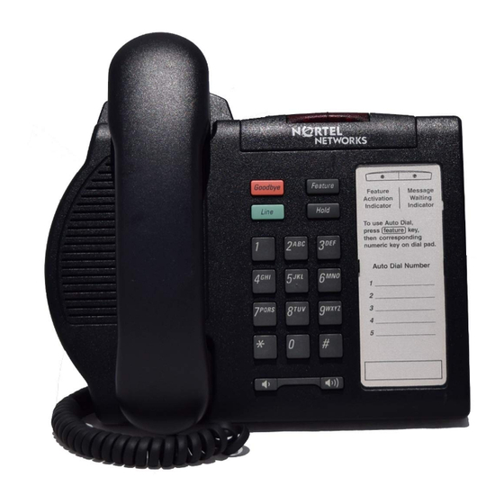
4 M3901 telephone set M3901 feature description The M3901 set has feature key activation. It takes only two keystrokes to activate a feature. For example, press the Feature key and a keypad number to activate a feature. The following key combinations can be activated: •... - Page 34 4-2 M3901 telephone set Figure 4-1 M3901 telephone set Message Waiting and Call Statu Feature Activation Indication NORTEL NETWORKS Goodbye Feature Line Hold Feature Card wxyz pqrs << >> Feature card The feature card enumerates the set directory and indicates the key sequence for feature activation.
-
Page 35: Message Waiting And Call Status Indicator (Mwi)
M3901 telephone set 4-3 Figure 4-2 Feature card example Feature Message Activation Waiting Indicator Indicator Activate a feature by pressing the Feature key and corresponding dial pad key Deactivate all features by pressing the Feature key and # key Message Waiting and Call Status Indicator (MWI) The MWI LED lights to show a message is waiting. -
Page 36: Line Key
Refer to the Service Order Reference Manual for additional information. M3901 key configuration Table 4-1 shows the M3901 set key configurations. Nortel Networks does not support the M3901 as a Call Center DN. The M3901 telephone firmware controls the Volume Control Bar, the Hold, and Goodbye keys. -
Page 37: M3902 Telephone Set
5 M3902 telephone set M3902 feature description The following list shows the M3902 set features: • one-line directory number (DN) • three programmable feature keys (self-labeled) • three fixed feature keys for Message, Transfer, and Options Note: Although the Message and Transfer keys are permanently labeled, they are not restricted to those features. - Page 38 5-2 M3902 telephone set Figure 5-1 Figure M3902 telephone set Handsfree Key & NORTEL NETWORKS DN icon DN 5000 Line Key Forward Adial Confer Programmable Feature Keys Navigation Options Keys Message wxyz pqrs Transfer Hold << >> Goodbye Mute Smart Mute Key & LED The following table describes the key numbers and their locations.
-
Page 39: Message Waiting Indicator (Mwi)
M3902 telephone set 5-3 Message waiting indicator (MWI) The MWI indicates that a message is waiting to be heard. This LED also flashes when the set is ringing. If the set is ringing when someone is leaving a message, the LED flashes until the set stops ringing. Display The display has two 31-character lines. -
Page 40: Navigation Keys
5-4 M3902 telephone set Table 5-2 M3902 icon indicators (Sheet 2 of 2) Icon Description DN/line icon Feature icon Navigation keys When the scroll icon displays, use the UP and DOWN keys to scroll the top display line. Use the UP, DOWN, LEFT, and RIGHT keys for other functions, depending on the active application and Options mode status. -
Page 41: Goodbye Key
M3902 telephone set 5-5 The Options key provides access to the following set parameters: • language — select the language in which to display information from English, Spanish, French, German, Swedish, Norwegian, Finnish, Italian, Brazilian, Portuguese, and Japanese • change Feature key label — change the feature labels from the default value •... -
Page 42: Mute Key And Indicator
Message, it doesn’t have to be datafilled as such. A SERVORD message displays stating that Message is the recommended feature for this key. In order to access voice mail without a message waiting, Nortel Networks recommends assigning Message to key 1 and Autodial to the Message key (key 6.) The Autodial key should be programmed with the voice mail system DN. -
Page 43: M3903 Enhanced Telephone
6 M3903 enhanced telephone M3903 general description The following list shows the M3903 telephone set features: • four directory numbers (DN) with three line display — two programmable line/feature (self-labeled) keys, each with two layers, providing up to four line/feature keys —... - Page 44 The following illustration shows the M3903 set and its characteristics. Figure 6-1 M3903 telephone set Message Waiting LED Handsfree Key & LED Primary DN Key Secondary DN or Feature Key (2 pages) NORTEL NETWORKS Hold Goodbye 5001 5000 00:00a JAN0...
-
Page 45: Message Waiting And Call Status Indicator (Mwi)
M3903 enhanced telephone 6-3 Table 6-1 shows the key numbers and locations for the M3903 set illustrated in figure 6-1. Table 6-1 Key numbers Key number Location key 1 labeled as Prime DN (shown as 5000) key 2 labeled as second Line/Feature (shown as 5001) key 3 labeled as Prime DN, accessed by using the Shift key (shown as 5000) -
Page 46: Info Line
6-4 M3903 enhanced telephone Info line The Info display line is 24 characters long. It displays information such as in use DN, user key presses, and time and date. Text line The 24 characters text display line shows information about the incoming call, such as calling party name, calling party DN, and call redirection. -
Page 47: Goodbye Key
M3903 enhanced telephone 6-5 • call timer enable — automatically time all calls and display the time for 10 seconds after the call disconnects • date/time format — choose the time and date format to display when the phone is idle •... -
Page 48: Headset With Led
In order to access voice mail without a message waiting, Nortel Networks recommends assigning message to key 1 and autodial to the message key (key 17.) The autodial key should be programmed with the voice mail system DN. -
Page 49: Compatible Features
M3903 enhanced telephone 6-7 • key 24 - speed call user (SCU), speed call short (SCS), or speed call long (SCL) • key 25 - privacy release • key 28 - Callers List • key 29 - Redial List Note: Keys 26-27 and 30-32 are reserved for future use. Keys 5-16 are not usable for the M3903 set. - Page 50 6-8 M3903 enhanced telephone 555-4001-136 Standard 04.02 May 2001...
-
Page 51: M3904 Professional Telephone
7 M3904 professional telephone M3904 feature description The following list shows the M3904 features: • 12 DNs with a five-line display • six self-labeled programmable line/feature keys with a second page of keys for a total of 12 • four context sensitive softkeys used to access context sensitive softkey features •... - Page 52 — Card View — No Matches Found Figure 7-1 illustrates the M3904 set and its characteristics. Figure 7-1 M3904 Telephone Handsfree Key & LED Message Waiting LED (2 pages) Programmable Feature Keys NORTEL NETWORKS 5001 Hold Goodbye Jack Jill 5000 JAN01...
- Page 53 M3904 professional telephone 7-3 Table 7-1 shows the key numbers and locations for the M3904 set. M3904 key numbers and locations Table 7-1 (Sheet 1 of 2) Key Number Location Key 1 labeled as Prime DN (shown as 5000) key 2 labeled as key 2;...
-
Page 54: Message Waiting Indicator (Mwi)
7-4 M3904 professional telephone M3904 key numbers and locations Table 7-1 (Sheet 2 of 2) Key Number Location key 25 Privacy Release (PRL) keys 26-37 NULL key 28 Callers List key 29 Redial List key 30-32 NULL Note: The shift key is used to access keys 7 through 12. Message Waiting Indicator (MWI) The MWI LED indicates that a message has been left and flashes when the set is ringing. - Page 55 M3904 professional telephone 7-5 Label line Shows the context sensitive softkey labels on the 24 character display line. Each feature label is up to seven characters with the an icon displaying the status of the feature. Navigation keys Use the up and down keys to scroll the display line when the icon displays. The up, down, left, and right keys are also used for other functions, depending on the active application and options mode status.
- Page 56 7-6 M3904 professional telephone • area code set-up — allows the user to enter area codes or prefixes to be used by the callers list. If this option is enabled, the callers list shows local numbers withoug the area code or internal numbers as extensions. Note: the area code data is stored in the callers list record, and it is displayed in brackets after the number.
- Page 57 SERVORD commands. Although it is permanently labeled as message, it does not have to be datafilled as such. In order to access voice mail without a message waiting, Nortel Networks recommends assigning message to key 1 and autodial to the message key (key 17.) The autodial key should be programmed with the voice mail system DN.
- Page 58 7-8 M3904 professional telephone Key-based Access Expansion Module (KBA) and Display-based Access Expansion Module (DBA) The M3904 set supports two KBAs or one DBA. Refer to the Hardware chapter of this document for more detailed information. Compatible features Refer to the Service Order Reference Manual. 555-4001-136 Standard 04.02 May 2001...
-
Page 59: M3905 Acd Telephone
8 M3905 ACD telephone M3905 Automatic Call Distribution (ACD) telephone feature description The following list shows the M3905 ACD telephone features: • eight programmable line/feature keys (self-labeled) with a four line display, giving the user access to eight line/feature keys •... - Page 60 — List View — Card View — No Matches Found Figure 8-1 shows the M3905 set and its characteristics. Figure 8-1 M3905 Telephone Set Server Applications Local Application Options Mode NORTEL NETWORKS Options Sarah 2223 5002 Hold Goodbye Supply Application...
- Page 61 M3905 ACD telephone 8-3 The following table contains the key configurations for the M3905. Table 8-1 M3905 key configuration (Sheet 1 of 2) key Number Description key 1 bottom right self-labeled programmable key (shown as DN5001) key 2 above key 1; line or feature (shown as Supply) key 3 above 2 (shown as 5002)
-
Page 62: Message Waiting Indicator (Mwi)
8-4 M3905 ACD telephone Table 8-1 M3905 key configuration (Sheet 2 of 2) key Number Description keys 26-27 NULL key 28 Callers List key 29 Redial List key 30-32 NULL Message Waiting Indicator (MWI) The MWI indicates that a message has been left. This LED also flashes when the set is ringing. - Page 63 M3905 ACD telephone 8-5 soft key for the current action to take effect and move one level up in the options list. While in options mode, the Line, Goodbye, and Hold keys can still be used to process calls but the display shows only options mode information. Options mode consists of an introduction screen that lists the number of available options and instructions for navigating the list of options.
-
Page 64: Goodbye Key
8-6 M3905 ACD telephone • headset port on call — enable or disable the call in progress indication feature. This feature requires a lamp-type accessory to be connected to the headset port of the terminal, which is signaled by the terminal while a call is in progress. -
Page 65: Directory/Log Key
Key 17 is called the message key but it is not restricted to that feature. This key appears with the context sensitive softkeys. In order to access voice mail without a message waiting, Nortel Networks recommends assigning message to key 1 and autodial to the message key (key 17.) The autodial key should be programmed with the voice mail system DN. -
Page 66: Key-Based Access Expansion Module (Kba) And Display-Based Access Expansion Module (Dba) Support
8-8 M3905 ACD telephone Key-based access expansion module (KBA) and display-based access expansion module (DBA) support The M3905 set supports one or two key-based KBAs or one DBA. Compatible features Refer to the Service Order Reference Manual. 555-4001-136 Standard 04.02 May 2001... -
Page 67: Hardware Options
9 Hardware options Table 9-1 lists optional hardware available for each telephone set. Table 9-1 Optional hardware accessories Optional hardware available M3901 M3902 M3903 M3904 M3905 Accessory Connection Module Supports Supports Supports Supports (ACM) Alternate key caps Supports Amplified Headset Accessory Supports Supports Supports... -
Page 68: Handset Option For The M3905 Automatic Call Distribution (Acd) Telephone
9-2 Hardware options Handset option for the M3905 Automatic Call Distribution (ACD) Telephone The M3905 set supports a non-amplified headset using the headset jack, an amplified headset using the handset jack, or an optional handset. The handset can be added to the M3905 set by removing the front plate of the telephone. A handset kit is optionally available for the M3905 set. -
Page 69: Accessories
— Wireless Amplified Headset — Liberation MPA I and II Note: MPA I is no longer offered by Nortel Networks. However, some customers have it and use it with the M3900 series sets. — Plantronics Polaris Note: The headsets are not offered by Nortel Networks, but the Plantronics may be obtained through Plantronics Polaris. - Page 70 9-4 Hardware options The audio output level from the MEARI varies with handset, headset, or handsfree. Levels vary between local and remote speech, and between users. For this reason, voice recorders with automatic level control (ALC) circuitry provide the best quality recordings and uniform recorded speech level. This is especially true for recording handsfree conversations which can provide the greatest range of speech level.
- Page 71 Hardware options 9-5 Key-based Access Expansion Module (KBA) The KBA has 22 keys which can be used as additional keys to the physical and self-labeled programmable feature keys on the M3900 series sets. These additional keys can be used as DN or feature keys. The sets and modules attach in such a way as they look and feel like one integrated unit.
- Page 72 9-6 Hardware options next logical set of feature keys shifting through the display. Visual indicator shows which page (or layer) of self-labeled programmable feature keys is in use. Note: The first key of the DBA maps to Key 33. Use SERVORD commands provision the DBA as a line option. Once a DBA has been added to a set, feature/DNs may be assigned to the extra keys.
- Page 73 The telephone wall mount bracket kit contains a one piece wall mount plate that attaches the M3903, M3904, and M3905 telephone to the wall. The wall mount kit is available from your local Nortel Networks distributor. The M3901 and M3902 have built in wall mount brackets.
- Page 74 9-8 Hardware options 555-4001-136 Standard 04.02 May 2001...
-
Page 75: 10 Installation
10-11 10 Installation How to install the M3900 series Meridian digital telephones The following procedure explains how to install the M3900 series Meridian digital telephones. Note: The station ringer test is not supported on the M3900 series sets. Procedure 10-1 Installing the M3900 Series Meridian Digital Telephones Complete the wiring and cross-connections (loop power). -
Page 76: Wall Mounting The Telephone
10-12 Installation With the position bar pressed in, raise or lower the telephone to the desired angle or height. Note: The M3903 and M3904 can be wall mounted. Release the bar to lock the telephone in the desired position. Changing the telephone angle The M3901 and M3902 Meridian digital telephones have three different angled height desktop positions. -
Page 77: How To Install The Accessory Connection Module (Acm)
Installation 10-13 Refer to your distributor for the latest product bulletin from Nortel Networks recommending headset types for use with the M3900 Series Digital Telephone. How to install the Accessory Connection Module (ACM) The following steps explain how to install the ACM. -
Page 78: Accessory Keying
Note 2: A wall transformer is required to power any accessory cartridges. The transformer does not come with the ACM unit. Contact your Nortel Networks distributor to order the ACM compatible wall transformer. Accessory keying There are two accessory ports on the back of the terminal footstand. -
Page 79: How To Install The Analog Terminal Adapter (Ata)
Installation 10-15 The shape and size of the plug in the accessory cartridge prevents the user from accidently connecting incompatible accessories. To check the compatibility of accessories, see Table 10-1 before buying optional hardware. Table 10-1 Compatibility of accessories External Display Key-based Personal... - Page 80 10-16 Installation connection capabilities between the M3902, M3903, M3904, and M3905 telephones and the ATA. Procedure 10-6 Installing the ATA Disconnect the line cord from the telephone before installing the ATA. Insert the ATA accessory cartridge into the ACM. The latch should be at the top.
- Page 81 Installation 10-17 Figure 10-2 ATA connections Refer to the manufacturer’s documentation for complete installation and configuration instructions for your external analog device (FAX machine, modem, or 500/2500 telephone). Note: The ATA supports connections to POTS services only. Features such as Message Waiting, Switchhook Flash/Link, Transfer, Conference, and CLASS type services are not supported on the attached device.
-
Page 82: How To Install The Meridian External Alerter And Recording Interface (Meari)
10-18 Installation telephone on the system equipment. Contact your system administrator for more information about flexible voice and data capability. When there is a power failure to the ATA, the Analog Device does not store or keep information (e.g., outgoing FAX from your FAX machine). You must send the information again when power returns. - Page 83 Installation 10-19 Figure 10-3 MEARI output connectors The following procedure describes how to install the MEARI. Procedure 10-7 Installing the MEARI The RJ12 modular connector provides access to all three output signals and is intended for wiring connection to remotely located equipment (not on the desktop).
- Page 84 10-20 Installation Figure 10-4 Loud ringer connected to the MEARI through the RJ12 jack MEARI desktop recording device The following illustration shows the MEARI desktop voice recording device. Figure 10-5 MEARI desktop voice recording device 555-4001-136 Preliminary 04.02 May 2001...
- Page 85 Installation 10-21 Note: The Mic Input reference to page 3 in the figure is not correct. Please see the MEARI information regarding automatic level control. MEARI call in progress indicator The following figures shows an illustration of the MEARI call in progress indicator.
- Page 86 10-22 Installation Figure 10-7 Remote voice recording using call status Troubleshooting The following procedure provides some troubleshooting examples for the MEARI. Procedure 10-8 Troubleshooting for the MEARI Ensure that the ACM power supply is connected to the telephone and plugged into a working AC outlet. Ensure that the MEARI is completely inserted and the release latch is engaged.
-
Page 87: Configure The Meridian Sl-100 Switch For The Kba
Installation 10-23 Configure the Meridian SL-100 switch for the KBA The following table shows an example of the commands used to configure the MSL-100 switch for the KBA in SERVORD. Table 10-4 SERVORD configuration for the KBA Prompt Response Description LEN or DN x...x... - Page 88 10-24 Installation Figure 10-8 Key-based Expansion Module Accessory Procedure 10-9 Installing the Key-based Expansion Module Accessory While depressing the telephone tilt handle, pull the telephone away from the footstand until it clears the final stop. Gently pull the footstand off the clips. Note: If an ACM is installed, leave the ACM cable plugged into the telephone, and swing the front edge of the footstand under the ACM cable to access the 10-pin...
-
Page 89: M3900 Series Kba Installation Sheet
Installation 10-25 Hook the Module footstand into the telephone footstand, and carefully turn the new assembly upright. Procedure 10-10 describes how to install a second KBA for the M3900 series sets. Add up to 2 KBAs to provide a total of 44 additional line/feature keys. Procedure 10-10 Installing the Key-based Expansion Module Accessory Place the telephone and the two Modules face down on a non-abrasive surface. -
Page 90: How To Install The Display-Based Expansion Module Accessory (Dba)
10-26 Installation How to install the Display-based Expansion Module Accessory (DBA) The DBA has eight programmable Line/Feature (self-labeled) keys with three layers. The DBA gives you a total of 24 programmable Line/Feature keys, keys 33-56. The DBA shows only eight of these features at one time. Use the Shift key to scroll to each key layer. -
Page 91: How To Install The Personal Directory Pc Utility
Installation 10-27 For more detailed SERVORD information, refer to the Commercial Systems Service Order Reference Manual. How to install the Personal Directory PC Utility The Personal Directory PC Utility provides a faster, easier way to create or modify a personal directory. Users can enter names and numbers into a Personal Directory file on their PC. -
Page 92: Install The Personal Directory Pc Utility
Click on Start. Select Run. Enter a:\setup. Click on OK. The Nortel Networks logo screen appears while the installation utility loads. The Welcome screen appears. Click on Next to continue installation. If you agree to the terms of the Software License Agreement, click Yes. -
Page 93: How To Select A Personal Directory Pc Utility Port
Installation 10-29 How to select a Personal Directory PC Utility port The following procedure shows how to select a port. Procedure 10-15 Selecting a Personal Directory PC Utility port Click on Phone. Click on Set port. The pull-down menu shows available PC ports: •... -
Page 94: Personal Directory Pc Utility Entry And File Standards
10-30 Installation Personal Directory PC Utility entry and file standards A Personal Directory PC Utility entry can have: • Up to 24 characters for the telephone number. • Up to 24 characters for the name. Each Personal Directory file can have a maximum of 100 entries (an entry is one line). -
Page 95: How To Modify A Personal Directory
Installation 10-31 How to modify a Personal Directory The following procedure shows how to modify a personal directory. Procedure 10-18 Modifying a Personal Directory Upload the directory you want to modify into an active window in the Personal Directory PC Utility. Select Phone on the Main Menu bar. -
Page 96: How To Delete A Directory Entry
10-32 Installation Procedure 10-22 Alternate delete function Highlight the character or number. Click on Edit on the Main Menu bar and click on Cut to delete. How to delete a directory entry The following procedure shows how to delete a directory entry. Procedure 10-23 Deleting a directory entry Position the cursor anywhere within the entry that you want to delete. -
Page 97: How To Program (Download) The Personal Directory
The handset does not accompany the M3905. The handset can be added the the M3905 by removing the front plate of the telephone. Note: Nortel Networks recommends that a system administrator complete this installation. MSL-100 M3900 Meridian Digital Telephones Reference Guide MSL15... - Page 98 10-34 Installation Figure 10-10 Front view removal of the hook switch cover 555-4001-136 Preliminary 04.02 May 2001...
-
Page 99: Installation Of The Cradle
Installation 10-35 Figure 10-11 Rear view removal of the hook switch cover There are five tabs and two hidden snaps on the Hook Switch cover. There are two tabs along the right tab tree along the bottom edge (front view.) To remove the cover, the hidden snaps must be released (rear view.) Procedure 10-27 Removal of the Hook Switch Cover Ease the cover to the left and pull on the left side to release the left snap. - Page 100 10-36 Installation 555-4001-136 Preliminary 04.02 May 2001...
-
Page 101: How To Install Alternate Key Caps For The M3905
Figure 10-12 How to install the cradle Procedure 10-28 How to install the cradle Hold the cradle in the same position as when you removed the Hook Switch Cover, move the cradle to the right to place the tab into the slot. Ease the other tabs on the bottom edge of the cradle into the slots. -
Page 102: How To Install The Full Duplex Handsfree Accessory On The M3904
Figure 10-13 How to install the alternate key caps As shown in the above figure, place the tips of the tool into the slots at the right and left of the key, grip tightly and pull straight upward. Procedure 10-29 Installing key caps Fit the two small elastomer posts in to two slots on the underside on the keys and firmly press downward. -
Page 103: Operating Parameters
Installation 10-39 Procedure 10-30 How to connect the FDHF Cartridge Check that your telephone is an M3904 Release III set (NTMN34GA) by looking at the label on the back. If it is, please continue to step 2. If it is not, the FDHF cartridge is not compatible with your telephone. -
Page 104: Status Light Indicator
Check the power connections to the cartridge. If problems continue, contact your network administrator. Configure the Meridian SL-100 for use with the FDHF Cartridge Table 10-8 Add a new M3904 telephone set with hadnsfree enabled via... - Page 105 Installation 10-41 Note: The M3904 telephone set must be a NTMN34GA or later vintage. If you are replacing an existing M3904 that currently has hnadsfree enabled, a datafill change is not required. MSL-100 M3900 Meridian Digital Telephones Reference Guide MSL15...
- Page 106 10-42 Installation 555-4001-136 Preliminary 04.02 May 2001...
-
Page 107: Environmental And Safety Considerations
11-1 11 Environmental and safety considerations This section address special considerations for the M3900 Series Meridian Digital Telephone: • temperature and humidity • line engineering Temperature and humidity Table 11-1 shows the temperature and humidity for operating and table 11-2 for storage. -
Page 108: Line Engineering
11-2 Environmental and safety considerations Table 11-2 Temperature and humidity Storage: Temperature range -50° to 70°C (-58° to 158°F) Relative humidity 5% to 95% (noncondensing). At temperatures above 34°C (93°F) relative humidity limited to 53 mbar of water vapor pressure. Line engineering M3900 Series Meridian Digital Telephones use twisted pair wiring on transmission lines. - Page 109 Environmental and safety considerations 11-3 Table 11-3 MEARI specifications (Sheet 2 of 2) Operating temperature 0ºC to 50ºC Humidity 5% to 95% Relative Humidity Dimensions (H x W x D) 1.25 x 3.75 x 4.65 inches 3.2 x 9.5 x 11.8 centimeters Weight 4 oz.
- Page 110 11-4 Environmental and safety considerations 555-4001-136 Standard 04.02 May 2001...
- Page 111 List of terms Automatic Answerback Key Answer Agent Automatic Call Distribution ACD DN ACD Mis ACD HOLD ACD Mis ACDNR Not Ready Accessory Connection Module SERVORD command for add Asynchronous Data Option AEMK Answer Emergency Automatic Level Control ACD Agent Status Lamp MSL-100 M3900 Meridian Digital Telephones Reference Guide MSL15...
- Page 112 A-2 List of terms Analog Terminal Adapter Automatic Dialing Automatic Line AUTODISP Automatic Display Feature Bearer Capability BCLID BCLID Feature Busy Lamp Field Blank Key Call Agent Key CCOS Controlled Class of Service CFDVT CFD Variable Timer Class of Service Separate Keylist for CFB Separate Keylist for CFD CFTOD...
- Page 113 List of terms A-3 CFUIF Separate Keylist CFUIF Call Forward SERVORD command for change feature Command Interpreter Controlled Interflow Calling Line Identify CLSUP Call Supervisor 4 to 30-way Conference CNF C06 6-party Conference Customer Originated Trace Call Park Call Progress Monitor CPND Calling Party Name Display Call Pick-up...
- Page 114 A-4 List of terms CWD Key Call Waiting Transfer DASK ACD Display Agents Display-based Access Expansion Module Data Communications Equipment DCPK Directed Call Park Data DN (Audits Only) Denied Incoming Digital Line Card DMCT DMCT Feature Do Not Disturb Directory Number Display Queue Status Display-Queue Threshold DRING...
- Page 115 List of terms A-5 DTMK Data Terminal Mode Keys Executive Busy Override Electronic Industries Association Emergency Executive Message Waiting SERVORD command for establish EXPEC Extended Peripheral Equipment Controller EXT ATR External Alerter ACD FAA Feature Activation Indicator Federal Communications Commission Fast Transfer GIAC Group Intercom All Calls...
- Page 116 A-6 List of terms Intercom Intermediate Distribution Frame INSPECT Inspect Key JOIN Call Join Key-based Access Expansion Module Key Set Short Hunt KSMOH Key Set Music On Hold Liquid Crystal Display Light Emitting Diode (lamp) Line of Business LPIC Primary Interlata Carrier Make Busy Key MBSCAMP MBS Camp On Key...
- Page 117 List of terms A-7 Make Set Busy MSMWI Multiple Set Message Waiting Indication MSQS Multistage Queue Status Message Waiting Indicator MWQRY Message Query Message Waiting SERVORD command for new NEWACD SERVORD command for new ACD NGTSRVCE ACD Night Service Key Observe Agent Originating Line Select OPTKEY...
- Page 118 A-8 List of terms Privacy Release Query Busy Station Quick Conference Key Ring Again RESETPWD CI command for password reset Random Make Busy Ringing Number Pick-up RSUS Requested_Suspension SACB Subscriber Call Block Selective Call Accept Selective Call Forward Speed Call Long SCMP Series Completion SCRJ...
- Page 119 List of terms A-9 Directory Number AT&T Line Study Security Code SERVORD Service Order Stop Hunt SLQLG Single Line Queueing Subscriber Line Usage SMDI Simplified Messages Station Origination Restrictions Special Billing Codes SSAC Station-Specification Authorization Codes SUPR Supervisor Feature Terminating Line Select Terminal Number TRKDISP Trunk Member Display...
- Page 120 A-10 List of terms TWCPUB TWCPUB Line Options UCDLG UCD Login Key UCDSD UCD SD Point Features MDC/RES Warm Line-NC0011 555-4001-136 Standard 04.02 May 2001...
- Page 121 The information contained in this document is the property of Nortel Networks. Except as specifically authorized in writing by Nortel Networks, the holder of this document shall keep the information contained herein confidential and shall protect same in whole or in part from disclosure and dissemination to third parties and use same for evaluation, operation, and mainte- nance purposes only.
Need help?
Do you have a question about the Meridian SL-100 and is the answer not in the manual?
Questions and answers