
Related Manuals for Quick 709D+


Summary of Contents for Quick 709D+
- Page 1 QUICK 709D+ Rework System Instruction Manual Thank you for purchasing our products. Please keep the instruction manual properly for future reference.
-
Page 2: Table Of Contents
Contents 1. Safety Instruction................错误!未定义书签。 2. Product Overview......................1 3. Product Features......................2 4. Product Specifications....................3 5. Display and Function Descriptions................4 5.1Dimensions......................4 5.2 Part descriptions....................4 5.3 Button descriptions..................5 5.3 Main menu......................6 6. Product Installation and Connection................7 6. 1 Soldering Station.....................7 6.1.1 Usage of soldering iron and cleaning sponge........ - Page 3 10. New Password Setup.....................10 11. Temperature Calibration..................11 11.1 Soldering temperature calibration.............11 11.2 Hot air temperature calibration..............12 12. Tip Maintenance......................13 13. Soldering Station Heater Replacement.............. 13 13.1 Steps of removing the heater..............14 13.2 Steps of replacing the heater..............14 14. Hot Air Heater Replacement.................15 14.1 Steps of removing Heater................
-
Page 4: Safety Instruction
1. Safety Instruction CAUTION During the installation and use of the product, you need to observe the electrical safety regulation of location. Please power off the product during disassembly. If the product is not working properly, please contact the supplier or manufacture, do not disassemble or modify without notice. -
Page 5: Product Overview
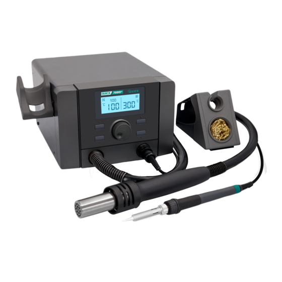
2. Product Overview This product is a 2-in-1 rework system which integrates hot air de-soldering and soldering. Two kinds of tools can cooperate with each other, easy to operate, suitable for the disassembly and soldering of various packaging components, suitable for maintenance and R&... -
Page 6: Product Specifications
4. Product Specifications Product model 709D+ Display Max power 1250W(soldering station70W)1350W(soldering station70W) Working voltage AC 110V AC 220V/230V Soldering station 100~480℃ temperature range Hot air temperature range 100~500℃ Hot air temperature stability ±5℃(Still air, no load) Soldering iron ±2℃(Still air, no load) temperature stability Hot air range 1~100 Level... -
Page 7: Display And Function Descriptions
5. Display and Function Descriptions 5.1Dimensions Unit: mm 5.2 Part Descriptions Part Name Hot air handle Handle holder Soldering iron handle Iron stand Air volume control knob ... -
Page 8: Button Descriptions
5.3 Button Descriptions Button Descriptions Button Descriptions Hot air temperature Soldering temperature increase button increase button Hot air temperature Soldering temperature ▲ ▼ decrease button decrease button Press and hold it at the Press and hold it at the same same time to enter the hot time to enter the soldering "+"... -
Page 9: Main Menu
5.4 Main Menu Hot air and iron working Sleep of hot air and iron working Hot air and iron OFF Icon Descriptions Icon Descriptions The soldering station The soldering station heating state thermostat status Fan rotation: Work The soldering station Fan stop: No work cooling state The hot air gun... -
Page 10: Product Installation And Connection
6. Product Installation and Connection 6. 1 Soldering Station 6.1.1 Usage of Soldering Iron and Cleaning Sponge 1) Wet the cleaning sponge first and then squeeze it dry. 2) Place the cleaning sponge into the groove of the base of the soldering iron stan 3) In the process of use, if the cleaning sponge gets dry, you should add water app ropriately. -
Page 11: Connection
3) Install the hot air handle holder, place the hot air handle on the hot air handle holder and check for suitability. Note: The hot air handle holder can be installed on the left or right side of the system according to actual needs. -
Page 12: Password Setup
Adjust the knob clockwise to increase the airflow, and otherwise decrease the airflow. The hot handle sleeping Place the handle on the holder to start cooling air and the product enters sleeping mode. 8. Password Setup The initial password is "000", and in this state, you can set the temperature. If you need to limit the temperature adjustment, you must change the password. -
Page 13: Parameter Setup
you can directly enter the second password.) 4) If the password entered twice is wrong: The menu will show "ERR", and then directly enter the main interface. 5) If the first or second password is correct: then go directly to parameter setting and the window shows "-1-". -
Page 14: Temperature Calibration
and hold the "▲" and "▼" button at the same time to confirm. The second setting method of password is the same as the first setting method of password. Note: If the number of password entered twice before and after is not the same, the window shows "ERR", which means the password setting is not successful, return to parameter setting, and the password remains unchanged. -
Page 15: Hot Air Temperature Calibration
Change the hot air temperature, press and hold "+" and "-" to confirm, and return to the main screen. Note: It is recommended to use QUICK 196 series hot air temperature tester to measure hot air temperature. If there is no QUICK196, it is recommended that the temperature tester be connected to the temperature head of the sensor and placed 3 to 5mm away from the air nozzle to measure the temperature. -
Page 16: Tip Maintenance
12. Tip Maintenance 1) When a new tip is used for the first time, set 250 to 280°C to protect the tip with solder. 2) Select the tip size according to the size of the solder joint. 3) To prevent tip oxidation, a fresh layer of solder should be plated before putting back into the soldering iron holder. -
Page 17: Steps Of Removing The Heater
13.1 Steps of removing the Heater 1) Pull out the ①Soldering tip and screw down the ⑤Nipple; 2) Pull out the ⑥Heater from the ⑪Handle body; 3) Pull out the ⑩Wire clamp from the ⑨Plastic part upward; 4) Unplug the three leads plugged into the heater pin; 5) Remove the ⑨Plastic part, ⑧Spring and ⑦Grounding spring . -
Page 18: Hot Air Heater Replacement
14. Hot Air Heater Replacement 14.1 Steps of removing Heater 1)Screw down ② Four screws; 2)Push the ⑥Handle assembly out of the ⑦Handle body; 3)Pull out ① Steel Pipe; 4)Pull out ③ Heater; 5)Performing replacements. Note: All operating steps are performed with the power disconnected and the handle cooled. -
Page 19: Troubleshooting
4)Screw on four ②Screws; This square is opposite the square hole of the terminal post. 5)After replacing the heater, the following measurements are recommended: 6)Calibrate the temperature, refer to Soldering temperature calibration. 15. Troubleshooting Error Fault Descriptions The sensor is error If the sensor or other parts of the sensor circuit fails, the "S-E"... -
Page 20: Tips
16. Tips... -
Page 21: Nozzles
17. Nozzles... -
Page 22: Consumable List
18. Consumable List A1124 A1130 Nozzle A1300 Heater TR3-H-ZZ-01-220V Steel pipe TR3-P-08H Mica paper ceramic packing Handle TR3-T Holder The handle sheath Pump components Fan module 863DW+ Sucking pad... - Page 23 960-B Heater H1901R Sensor The Hot Pad Sponge Encloser RF02H-03-03 Steel Pipe 901A-05 Nipple 901A Fuse 10A/5x20mm(VDE) Wire Cleaning Ball 65/Copper clean ball/13g Iron Stand Soldering Iron QUICK901RAA...
Need help?
Do you have a question about the 709D+ and is the answer not in the manual?
Questions and answers