Table of Contents
Advertisement
Quick Links
KONA M
TDD
User Guide
Document Type:
Document Number:
Document Issue:
Document Status:
Product Name:
Product Code:
Issue Date:
TEKTELIC Communications Inc.
th
7657 10
Street NE
Calgary, AB, Canada T2E 8X2
Phone: (403) 338-6900
© 2022 TEKTELIC Communications Inc., all rights reserved.
All products, names, and services are trademarks and registered trademarks of their respective companies.
G
EGA
ATEWAY
User Guide
T0008387_UG
1.0
Approved
KONA Mega Gateway
See Table 1
October 14, 2022
– 900MH
Z
Advertisement
Table of Contents

Related Manuals for TEKTELIC Communications T0004978


Summary of Contents for TEKTELIC Communications T0004978
- Page 1 October 14, 2022 TEKTELIC Communications Inc. 7657 10 Street NE Calgary, AB, Canada T2E 8X2 Phone: (403) 338-6900 © 2022 TEKTELIC Communications Inc., all rights reserved. All products, names, and services are trademarks and registered trademarks of their respective companies.
- Page 2 Document Revision Issue Revision Status Editor Comments Date Oct. 12, 2022 Draft K. Minderhoud Original Draft Oct. 14, 2022 Released K. Minderhoud Approved KONA Mega Gateway User Guide T0008387_UG Version 1.0 TEKTELIC Communications Inc. Page 2 of 20...
-
Page 3: Table Of Contents
RF Cable Installation ....................... 16 Antenna Installation ....................... 16 Copper Ethernet Cable Installation ................17 Radio Compliance Statements ....................18 Déclarations de conformité à la radio ................... 20 KONA Mega Gateway User Guide T0008387_UG Version 1.0 TEKTELIC Communications Inc. Page 3 of 20... - Page 4 Table 2: KONA Mega Gateway Interface Connector Types ............10 Table 3: KONA Mega Gateway Specifications................10 Table 4: Maximum 3G/4G antenna gain ..................16 KONA Mega Gateway User Guide T0008387_UG Version 1.0 TEKTELIC Communications Inc. Page 4 of 20...
- Page 5 Figure 6: KONA Module with Mounting Bracket ................13 Figure 7: Chassis Ground Connection ................... 14 Figure 8: Direct DC Power CPC Connector Connection Polarity ........... 15 KONA Mega Gateway User Guide T0008387_UG Version 1.0 TEKTELIC Communications Inc. Page 5 of 20...
-
Page 6: Product Description
Figure 4 T0004988 Figure 2 T0004992 Figure 4 T0004996 Figure 2 T0005000 Figure 4 T0005004 Figure 2 T0005006 Figure 3 T0005008 Figure 4 T0005010 Figure 5 KONA Mega Gateway User Guide T0008387_UG Version 1.0 TEKTELIC Communications Inc. Page 6 of 20... -
Page 7: Figure 1: Kona Mega Gateway Common Dimensions
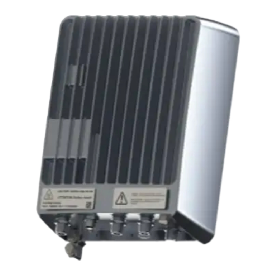
Figure 1 illustrates the common Gateway external form-factor. The differences between the options are limited to the bulkhead field, and the internal cavity bandpass filters. Figure 1: KONA Mega Gateway Common Dimensions KONA Mega Gateway User Guide T0008387_UG Version 1.0 TEKTELIC Communications Inc. Page 7 of 20... -
Page 8: Bulkhead Layout
Figure 2: KONA Mega Gateway Option #1 with Circular Plastic Connector Bulkhead Field LTE Antenna Port Figure 3: KONA Mega Gateway Option #2 with Circular Plastic Connector Bulkhead Field KONA Mega Gateway User Guide T0008387_UG Version 1.0 TEKTELIC Communications Inc. Page 8 of 20... -
Page 9: Figure 4: Kona Mega Gateway Option #3 With Circular Plastic Connector Bulkhead Field
Connector types and their mating connectors are listed in Table 2 . KONA Mega Gateway User Guide T0008387_UG Version 1.0 TEKTELIC Communications Inc. Page 9 of 20... -
Page 10: Specifications
All interfaces are protected to primary levels except for the 3G/4G modem Surge Protection antenna port which supports local antenna mounting only or requires an external surge suppressor. KONA Mega Gateway User Guide T0008387_UG Version 1.0 TEKTELIC Communications Inc. Page 10 of 20... -
Page 11: Installation
10 A. The overcurrent protection must have the appropriate current interrupt capacity for the power source and must be incorporated into the non-earthed conductor(s) of the KONA Mega Gateway DC supply. KONA Mega Gateway User Guide T0008387_UG Version 1.0 TEKTELIC Communications Inc. Page 11 of 20... -
Page 12: Unpacking And Inspection
(four M6x1.0 - 14 mm bolts with flat and star lock washers) as illustrated in Figure 6. The Gateway module must be oriented with the connector bulkhead facing down, towards earth. KONA Mega Gateway User Guide T0008387_UG Version 1.0 TEKTELIC Communications Inc. Page 12 of 20... -
Page 13: Figure 6: Kona Module With Mounting Bracket
4. Insert and tighten two additional site supplied M8 bolts through the holes at the bottom of the bracket. The KONA Mega Gateway pole mounting procedure is as follows: KONA Mega Gateway User Guide T0008387_UG Version 1.0 TEKTELIC Communications Inc. Page 13 of 20... -
Page 14: Ground Cable Installation
4. Install the ground cable through its 2-hole lug onto the chassis ground point using the two supplied 1/4 - 20 x 1/2” bolts with flat and star lock washers, torqued to 10.4 Nm (92 in·lbs). Figure 7: Chassis Ground Connection KONA Mega Gateway User Guide T0008387_UG Version 1.0 TEKTELIC Communications Inc. Page 14 of 20... -
Page 15: Direct Dc Power Cable Installation
The CPC DC connector shall be as specified in Table 2 and shall follow the signal polarity identified in Figure 8. DC Positive DC Negative Figure 8: Direct DC Power CPC Connector Connection Polarity KONA Mega Gateway User Guide T0008387_UG Version 1.0 TEKTELIC Communications Inc. Page 15 of 20... -
Page 16: Rf Cable Installation
Band Frequency (MHz) Maximum Antenna Gain (dBi) 1850–1910 1710–1755 824–849 777–787 704–716 1850–1915 1850–1910 UMTS 1710–1755 824–849 824–849 1900 1850–1910 824–849 CDMA 1850–1910 BC10 817–824 KONA Mega Gateway User Guide T0008387_UG Version 1.0 TEKTELIC Communications Inc. Page 16 of 20... -
Page 17: Copper Ethernet Cable Installation
Table 2 must be used. The Ethernet cable must have minimum 24 AWG conductors and shall be rated for outdoor application according to local and national electrical codes. KONA Mega Gateway User Guide T0008387_UG Version 1.0 TEKTELIC Communications Inc. Page 17 of 20... -
Page 18: Radio Compliance Statements
Before servicing the product, the antenna(s) or cables, turn off the transmission function or the unit power if you have to get closer than the minimum separation distance. The 3G/4G modem antenna maximum allowed gain including cable loss shall be in accordance with the following table: KONA Mega Gateway User Guide T0008387_UG Version 1.0 TEKTELIC Communications Inc. Page 18 of 20... - Page 19 Band Frequency (MHz) Maximum Antenna Gain (dBi) 1850–1910 1710–1755 824–849 777–787 704–716 1850–1915 1850–1910 UMTS 1710–1755 824–849 824–849 1900 1850–1910 824–849 CDMA 1850–1910 BC10 817–824 KONA Mega Gateway User Guide T0008387_UG Version 1.0 TEKTELIC Communications Inc. Page 19 of 20...
-
Page 20: Déclarations De Conformité À La Radio
Band Frequency (MHz) Gain maximum d'antenne (dBi) 1850–1910 1710–1755 824–849 777–787 704–716 1850–1915 1850–1910 UMTS 1710–1755 824–849 824–849 1900 1850–1910 824–849 CDMA 1850–1910 BC10 817–824 KONA Mega Gateway User Guide T0008387_UG Version 1.0 TEKTELIC Communications Inc. Page 20 of 20...
Need help?
Do you have a question about the T0004978 and is the answer not in the manual?
Questions and answers