TEKTELIC Communications Kona Macro Gateway User Manual
Hide thumbs
Also See for Kona Macro Gateway:
- Quick start manual (14 pages) ,
- Quick start manual (4 pages)
Table of Contents
Advertisement
Available languages
Available languages
TEKTELIC C
Document type:
Document number:
Document version:
Document Status:
Product name:
Product codes:
TEKTELIC Communications Inc.
th
7657 10
Street NE
Calgary, AB, Canada T2E 8X2
Phone: (403) 338-6900
© 2019 TEKTELIC Communications Inc., All rights reserved.
All products, names and services are trademarks and registered trademarks of their respective companies.
Disclaimer:
Material contained in this document is subject to change without notice. The material herein is solely for
information purposes and does not represent a commitment by TEKTELIC or its representatives. TEKTELIC has
prepared the information contained in this document solely for use by its employees, agents, and customers.
Dissemination of this information and/or concepts to other parties is prohibited without the prior written consent
of TEKTELIC. In no event will TEKTELIC be liable for any incidental or consequential damage in connection with the
furnishing, performance or use of this material.
TEKTELIC reserves the right to revise this publication in accordance with formal change control procedures defined
by TEKTELIC.
OMMUNICATIONS
User Guide
T0005158_UG
0.6
Approved
Kona Macro Gateway
See Table 1
I
.
NC
Advertisement
Table of Contents

Related Manuals for TEKTELIC Communications Kona Macro Gateway


Summary of Contents for TEKTELIC Communications Kona Macro Gateway
- Page 1 Street NE Calgary, AB, Canada T2E 8X2 Phone: (403) 338-6900 © 2019 TEKTELIC Communications Inc., All rights reserved. All products, names and services are trademarks and registered trademarks of their respective companies. Disclaimer: Material contained in this document is subject to change without notice. The material herein is solely for information purposes and does not represent a commitment by TEKTELIC or its representatives.
- Page 2 Apr 24, 2019 Approved Z. Herasymiuk T-Code Table Added Pt 27 FCC to Regulatory Table Jul 30, 2019 Approved Z. Herasymiuk Added Proposition 65 Statements Kona Macro User Guide T0005158_UG Version 0.6 TEKTELIC Communications Inc. Confidential Page 2 of 32...
-
Page 3: Table Of Contents
Installation ..........................10 Safety Precautions ......................10 Unpacking and Inspection ....................11 Required Equipment for Installation ................11 Kona Macro Gateway Mounting ..................11 Ground Cable Installation ....................14 Direct DC Power Cable Installation ................15 RF Cable Installation ....................... 16 Copper Ethernet Cable Installation ................ - Page 4 ..................31 Kona Macro User Guide T0005158_UG Version 0.6 TEKTELIC Communications Inc. Confidential Page 4 of 32...
-
Page 5: Product Description
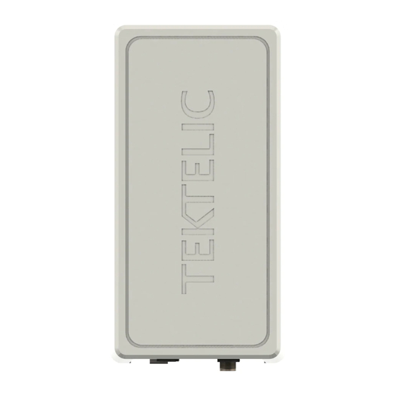
1 Product Description Overview The Kona Macro Gateway is an outdoor hardened LoRaWAN IoT gateway that supports the full range of LoRa WAN channels. The Gateway supports one external LoRa antenna, an internal GPS antenna, two power options including direct DC input power or Power over Ethernet (PoE), and two backhaul options including copper Ethernet or 3G/4G wireless. - Page 6 North America 2 T0006033 North America 2 T0006034 Figure 1 illustrates the Kona Macro Gateway external form-factor with the front view on the left and rear view on the right. All models share the same mechanical form-factor. Kona Macro User Guide T0005158_UG Version 0.6...
-
Page 7: Physical Interfaces
Figure 1: Kona Macro Gateway Common Dimensions Physical Interfaces Figure 2 illustrates the bulkhead layout for the Kona Macro Gateway. All models share the same bulkhead layout. Kona Macro User Guide T0005158_UG Version 0.6 TEKTELIC Communications Inc. Confidential Page 7 of 32... - Page 8 Connector types and their mating connectors are listed in Table 2. Table 2: Kona Macro Gateway Interface Connector Types Interface Connector Type...
-
Page 9: Specifications
Chassis Protective Earth Industry standard 2-hole lug, 1/4 x 0.75” spacing Earth Ground Ground terminal Specifications The Kona Macro Gateway specifications are listed in Table 3. Table 3: Kona Macro Gateway Specifications Attribute Specification Dimensions 222.2mm (8.7”) wide x 101mm (4.0”) deep x 287.3mm (11.3”) tall Weight 5.1 kg (11.3 lbs) -
Page 10: Installation
2 Installation Safety Precautions • The Kona Macro Gateway must be installed in a restricted access location (such that touching of the Gateway by non-service persons is not likely). • The Kona Macro Gateway may become hot to the touch during normal operation at elevated ambient temperatures. -
Page 11: Unpacking And Inspection
• Although the Kona Macro Gateway can be powered through either the direct DC input or the power over Ethernet (PoE) input, simultaneous application of power to both inputs may result in unexpected operation and shall be avoided. • The Kona Macro Gateway power source must meet SELV requirements. - Page 12 Mounting screw location Figure 3: Kona Macro Gateway Mounting Bracket Attachment Screw Locations The mounting bracket is a single part that bolts to the back surface of the Gateway using supplied hardware (four M6x1.0 - 14 mm bolts with flat and star lock washers) as illustrated in Figure 4.
- Page 13 2mm gap from the wall surface. 3. Hang the Kona Macro Gateway with bracket from the two bolts by inserting the keyhole slots at the top of the bracket onto the 2 bolts and tightening the bolts.
-
Page 14: Ground Cable Installation
Protective Earth Ground conductor terminated at the double hole lug point is mandatory and must be the first connection made to the Kona Macro Gateway during installation. Proper routing and termination of this cable is key to robust lightning withstand performance; in high susceptibility installations, every effort shall be made to minimize connection inductance and ground bed resistance. -
Page 15: Direct Dc Power Cable Installation
Figure 5: Chassis Ground Connection Direct DC Power Cable Installation The Kona Macro Gateway direct DC feed terminates at a dedicated two pin circular plastic connector (CPC) on the bulkhead. The direct DC power input is isolated from chassis (earth) with the exception of the primary surge suppressors. -
Page 16: Rf Cable Installation
Figure 6: Direct DC Power CPC Connector Connection Polarity RF Cable Installation The Kona Macro Gateway installation requires connection to a LoRa RF antenna. The RF cable attaches to the N-Type connector located on the bulkhead of the Gateway. Torque the connector to 1.7 to 2.3 Nm (15 to 20 in·lbs). -
Page 17: Radio Compliance Statements
Before servicing the product, the antenna(s) or cables, turn off the transmission function or the unit power if you have to get closer than the minimum separation distance. This product must be installed by professional trained RF technicians. Kona Macro User Guide T0005158_UG Version 0.6 TEKTELIC Communications Inc. Confidential Page 17 of 32... -
Page 18: Description Du Produit
LoRa externe, une antenne GPS interne, deux options d'alimentation, y compris une alimentation CC directe ou Power over Ethernet (PoE), et deux options backhaul, y compris Ethernet cuivre ou 3G / 4G sans fil. Le tableau 4 présente les modèles Kona Macro Gateway actuellement disponibles pour le marché nord-américain.. - Page 19 North America 2 T0006034 Figure 7 illustre le facteur de forme externe Kona Macro Gateway avec la vue de face sur la gauche et la vue arrière sur la droite. Tous les modèles partagent le même facteur de forme mécanique.
-
Page 20: Interfaces Physiques
Figure 7: Kona Macro Gateway Dimensions communes Interfaces physiques Figure 8 illustre la disposition de la cloison de la Kona Macro Gateway. Tous les modèles partagent la même disposition de cloison. Kona Macro User Guide T0005158_UG Version 0.6 TEKTELIC Communications Inc. - Page 21 3G / 4G protection Figure 8: Kona Macro Gateway Mise en page de cloison Tous les modules d'interconnexion du module Kona Gateway se trouvent sur la cloison inférieure. Les connecteurs RF sont imperméables à l'eau, mais tous les autres connecteurs doivent être terminés avec des connecteurs correspondants ou recouverts avec le capuchon de protection...
-
Page 22: Spécifications
Terre Terre de 1/4 x 0,75 " châssis Spécifications Les spécifications de Kona Macro Gateway sont répertoriées dans Table 6. Table 6: Kona Macro Gateway Spécifications Attribute Spécifications Dimensions 222.2mm (8.7”) large x 101mm (4.0”) Profond x 287.3mm (11.3”) grand Poids 5.1 kg (11.3 lbs) - Page 23 FCC Pt. 15, RSS-247, EN 301 489-1 FCC Pt. 27 (North American 2 variante seulement) Protection contre les Toutes les interfaces sont protégées aux niveaux primaires. surtensions Kona Macro User Guide T0005158_UG Version 0.6 TEKTELIC Communications Inc. Confidential Page 23 of 32...
-
Page 24: Installation
5 Installation Précautions de sécurité • La passerelle Kona Macro Gateway doit être installée dans un endroit à accès restreint (de sorte que le contact avec la passerelle par des personnes qui ne sont pas en service est peu probable). -
Page 25: Déballage Et Inspection
Montage de la passerelle Kona Macro Kona Macro Gateway est conçu pour être monté sur un poteau ou un mur vertical en utilisant le support de montage fourni qui se fixe aux quatre emplacements de vis à l'arrière du module illustré... - Page 26 Figure 9: Emplacements des vis de fixation du support de montage Kona Macro Gateway Le support de montage est une pièce unique qui se boulonne sur la surface arrière de la passerelle à l'aide de la quincaillerie fournie (quatre boulons M6x1.0 - 14 mm avec rondelles de blocage plates et en étoile) comme illustré...
- Page 27 "), laissant les têtes en saillie avec un espace de 2 mm de la surface du mur. 3. Accrochez la Kona Macro Gateway avec le support des deux boulons en insérant les fentes en trou de serrure au sommet du support sur les 2 boulons et en serrant les boulons..
-
Page 28: Installation Du Câble De Masse
1/4 x 0,75 po jusqu'au point de terminaison au sol illustré à Figure 11. La jauge de câble de masse recommandée est # 10 AWG. Le système de mise à la terre Kona Macro Gateway doit être conforme aux codes électriques locaux et nationaux. Le conducteur de terre de protection terminé au point de cosse à double trou est obligatoire et doit être la première connexion faite à... -
Page 29: Installation Directe Du Câble D'alimentation Cc
Figure 11: Connexion au sol du châssis Installation directe du câble d'alimentation CC L'alimentation CC directe Kona Macro Gateway se termine par un connecteur en plastique circulaire à deux broches (CPC) dédié sur la cloison. L'entrée d'alimentation CC directe est isolée du châssis (terre) à... -
Page 30: Installation Du Câble Rf
Figure 12: Polarité de connexion du connecteur CPC d'alimentation CC directe Installation du câble RF L'installation de Kona Macro Gateway nécessite une connexion à une antenne RF LoRa. Le câble RF se branche sur le connecteur N-Type situé sur la cloison de la passerelle. Serrez le connecteur de 1,7 à... - Page 31 à 30dBm au total . Les antennes doivent être installées à un endroit offrant une distance de séparation d'au moins 13,8 pouces (35 cm) de tout corps humain. Kona Macro User Guide T0005158_UG Version 0.6 TEKTELIC Communications Inc. Confidential Page 31 of 32...
- Page 32 Avant de réparer le produit, l'antenne ou les câbles, désactivez la fonction de transmission ou l'alimentation de l'unité si vous devez vous rapprocher de la distance de séparation minimale. Ce produit doit être installé par des techniciens RF qualifiés. Kona Macro User Guide T0005158_UG Version 0.6 TEKTELIC Communications Inc. Confidential Page 32 of 32...
Need help?
Do you have a question about the Kona Macro Gateway and is the answer not in the manual?
Questions and answers