
Related Manuals for SOLARFOCUS maximus L 150


Summary of Contents for SOLARFOCUS maximus L 150
- Page 1 Commercial boiler maxi mus L Installation manual for qualified personnel Read carefully before operating. DR-0160-EN / v25-202206...
-
Page 2: Table Of Contents
1 About this manual Content 1 About this manual 6 Hydraulic connection 1.1 Limitation of liability 6.1 Boiler connections 2 Safety information 7 Electrical connection 7.1 Power supply for the heating system 3 Technical requirements 7.2 Boiler control cabinet 3.1 Warranty, guarantee, liability 7.3 Terminal assignment 3.1.1 Technical requirements for warranty and gua- 7.4 Connections, functions... -
Page 3: Limitation Of Liability
1.1 Limitation of liability Recommendation: Conclude maintenance con- tract SOLARFOCUS GmbH accepts no liability for injury or – Have repairs carried out by qualified personnel material damage resulting from: only. Improper repairs can lead to risks for the –... -
Page 4: Technical Requirements
– Soften the fill-up water, or better: desalinate it. usage. – We are not liable for parts that were not produced by SOLARFOCUS. However, we are prepared to transfer our existing claims against the producer (relating to this defect) to the buyer. -
Page 5: Claims Rendered Void
– EN 303-5 - Part 5: Heating boilers for solid fuels, – The repair and/or warranty replacement shall be manually and automatically stoked, nominal heat carried out on site or in the SOLARFOCUS fac- output of up to 500 kW tory at our discretion. -
Page 6: Installation Room
3 Technical requirements Chimney 3.3 Installation room – The chimney must be resistant to moisture. Use Structural specifications fire brick or stainless steel. – The boiler may only be installed in a dry, frost-free – The chimney must conduct away the flue gases room;... -
Page 7: Supply Air In The Installation Room
3 Technical requirements Execution of the flue gas pipe Install explosion flap – Run the flue gas pipe towards the chimney in a short and rising direction, with as few chan- Abb. 2-1: Explosion flap integrated into draught stabiliser ges of direction as possible. Before longer horizontal pipe sections –... -
Page 8: Heating System Fill-Up Water
3 Technical requirements Calculation of the total permitted hardness of the Minimum space [in cm²] including 20% fill-up water surcharge for grids Boiler To use the table, the specific system volume for the Austria Germany Switzerland power system must be determined: Supply [In kW] Supply... -
Page 9: Intermediate Storage
3 Technical requirements Electrical conductivity Pressure equalisation through expansion tank – The expansion tank prevents air from being The probability of corrosion usually decreases with decreasing electrical conductivity of the heating drawn in when the system cools down (issue: oxy- water. -
Page 10: Product Information
4 Product information Hydraulic switch 4 Product information – A hydraulic switch separates the flows in the boi- ler and heating circuits. 4.1 Product description – If the heating system is operated without a buffer tank, a hydraulic switch must be installed bet- ween flow and return. -
Page 11: Safety Devices
3 Technical requirements Wood chips Overtemperature reset (OTR) Use wood chips only in accordance with these spe- cifications: – Wood chips according to the EN ISO 17225- 4:2014 standard – Permissible classes A1, A2, B1 Not permissible: Class B2 – Sizes P16S and P31S –... - Page 12 3 Technical requirements Safety valve (to protect against excess pres- Temperature monitor in the fuel storage sure in the system) room (TM) – The safety valve is a safety device for protecting against overpressure in the water circuit of the heating system.
- Page 13 3 Technical requirements Rotary valve If this device is not used, both connections must be sealed shut. False air will otherwise The rotary valve fulfils all normative requirements for be drawn into the burner, which will impair bur- the approved fuels regarding fire protection, burn- ner performance.
-
Page 14: Accessories
3 Technical requirements 4.4 Accessories External ash extraction system – Optional accessories – Ash extraction system with 240 litre standard bin, item 63791 – Ash extraction system with 600 litre tipping con- tainer, item 63793 – Further information is provided in the docu- mentation of the ash extraction system, DR-9969 Abb. -
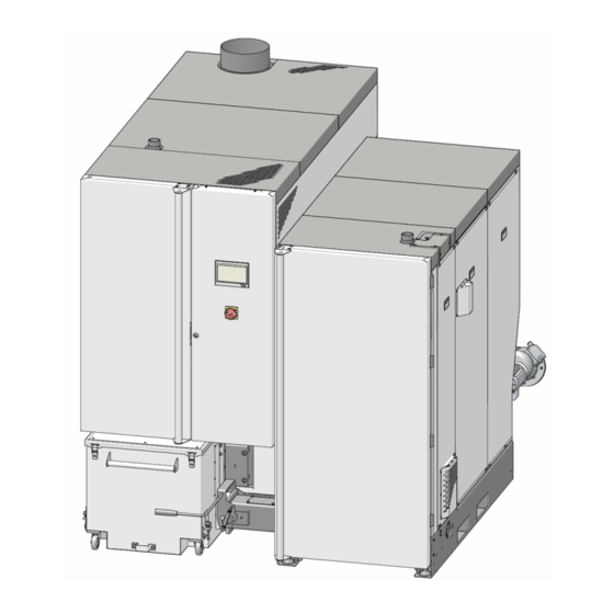
Page 15: Dimensions
3 Technical requirements 4.6 Dimensions The following figures show the maxi L with mounted intermediate pellet store. Top view Abb. 2-9 Installation manual maximus L... - Page 16 3 Technical requirements Front Abb. 2-10 Side view Abb. 2-11 Installation manual maximus L...
-
Page 17: Functional Components, Combustion Principle
3 Technical requirements 4.7 Functional components, combustion principle Burner Abb. 2-12: Section through the burner Functional components 1 Rotary valve 5 Ash auger burner Rotary drive for secondary air 2 Feeder unit 6 Ash container 10 Secondary air outlet 3 Push grate 7 Rotary drive for primary air 11 Flue gas recirculation line 4 Ash scraper... - Page 18 3 Technical requirements Heat exchanger Abb. 2-13: Cross section through heat exchanger Functional components Flue gas pipe connecting flange Flue gas pipe Ash auger heat exchanger Heat exchanger Ash auger burner Main switch Electrostatic dust collector Ash container Flue gas guide –...
-
Page 19: Technical Specifications
3 Technical requirements 4.8 Technical specifications maxi Wood chips output [kW] Pellets output [kW] Boiler class (acc. to EN 305:5 2012) Dimensions Width [cm] Height inc. adjustable feet [cm] Depth with ID fan [cm] Burner transport dimension - width [cm] Heat exchanger transport dimension - [cm] width Heat exchanger transport dimension -... - Page 20 3 Technical requirements maxi Emissions according to test report: Wood chips Flue gas values (in relation to 13% O 18-IN-AT-UW-OÖ- 18-IN-AT-UW-OÖ- Interpolation accor- from test report:testing institute/test EX-205/3 EX-205/4 ding to EN 303-5 TÜV Austria TÜV Austria report No. CO full load [mg/m³] CO partial load [mg/m³]...
-
Page 21: Wood Chipclassification
3 Technical requirements 4.9 Wood chipclassification according to EN ISO 17225-4 standard Property class > 21 Unit Woodland timber and plan- Complete trees without roots; tation wood as well as other Trunk wood; Origin, source natural timber; Woodland offcuts; Chemically untreated waste Chemically untreated waste timber timber Particle size P... - Page 22 3 Technical requirements Bulk density (kg/m³) Water content 8 to 18 18 to 25 25 to 35 (with moist mass being reference base) Bulk volume [kg/m³] 160 to 180 180 to 200 200 to 225 Conifer tree species Property class BD150 BD150 BD200...
-
Page 23: Installation
5 Installation 5 Installation When the load of the burner is taken from the front, the front door must first be removed. When the load of the heat exchanger is taken 5.1 Transport from the rear, some of the mechanical com- ponents must first be removed (electric motor, Option 1: Transport with an industrial/fork-lift gearbox, drive chain,…). -
Page 24: Connecting Heat Exchanger And Burner
5 Installation 5.3.1 Adjust spacing screws 5.3 Connecting heat exchanger and bur- ► The two lower holes serve to receive the spa- cing adjustment screws. This chapter describes how to make the necessary Abb. 2-19: Hole for screws connections between the heat exchanger and the bur- ner. -
Page 25: Screw On Flue Gas Pipe Flange
5 Installation ► Mount auger trough 5.3.2 Screw on flue gas pipe flange on heat exchanger. ► Connect the flange of the flue gas pipe with 6× hexagon screws and nuts. Abb. 2-23: Mount the auger channel ► Push metal ring and gasket onto auger Abb. -
Page 26: Connect Flue Gas Recirculation Line
5 Installation ► Mount auger trough ► Mount geared motor on auger shaft 1. on burner with 4× hexagon ► Use key screws and washers. Enclose seal 2. and two securing rings Abb. 2-26: Mount the auger channel Abb. 2-29: Drive on right side of burner 5.3.4 Connect flue gas recirculation line ►... -
Page 27: Connect Burner And Heat Exchanger Hydraulically
5 Installation 5.3.5 Connect burner and heat exchanger Connect the feed grate motor ► Connect the pre-routed cable as shown in the ter- hydraulically minal area of the motor. ► Join and insulate both connections (pipe and insulation not included in scope of delivery) Abb. -
Page 28: Install The Hot Air Fan
5 Installation Install the feeder sensor 5.6 Install the hot air fan ► Fix the feeder sensor in the retaining tube ► Mount cover and 2. ► Connect to A1:X33, cable is pre-routed in ducts ► Install hot air fan in ignition pipe and secure 3 and 2 >... -
Page 29: Installing Thermal Overload Protection
5 Installation ► Fit the thermal overload protection valve 5.9 Installing thermal overload protection before (as seen from the direction of flow) The boiler maxi L has two safety heat the safety heat exchanger (i.e. no water pres- exchangers installed (one in the burner, one in sure building up in the heat exchanger). -
Page 30: Flue Gas Pipe: Hole For Emission Measurement
5 Installation 5.12.1 Flue gas pipe: Hole for emission mea- 5.13 Mounting ash container surement ► Make the hole for the emission measurement according to the following images (recom- mendation according to standard). ► If these specifications cannot be implemented, then make the measuring point after a calming section, i.e. -
Page 31: Mounting Cladding On The Boiler
5 Installation Latch in ash container 5.14 Mounting cladding on the boiler ► Press lever down to the stop. The ash con- ► Mount two covers on the back. tainer is thereby pressed against the auger chan- nel. Illustration of further boiler covers >... -
Page 32: Hydraulic Connection
6 Hydraulic connection Return sensor, pressure sensor 6 Hydraulic connection 6.1 Boiler connections Boiler flow, boiler return Abb. 2-48 1 Return sensor 2 Pressure sensor 3 blank Abb. 2-46 Boiler draining 1 Boiler flow, G 2” OT 2 Boiler return, G 2” OT Feeler, immersion sleeves Abb. -
Page 33: Electrical Connection
7 Electrical connection Establish potential equalisation 7 Electrical connection DANGER - There is a risk of fatal electric shocks when working on electrical components of the system – Connect the two parts (burner and heat – Work may be performed only by a qualified exchanger) to the potential equalisation electrician. -
Page 34: Terminal Assignment
7 Electrical connection Components (power elements,…) in the control 7.3 Terminal assignment cabinet Designation Connection Flue gas temperature sensor > 47 A1:X34 Motor > 36 A1:X16 Ash extraction burner: Ash extraction heat exchanger (and separator clea- A1:X23 Motor > 47 ning): Ash extraction heat exchanger (and separator clea- A1:X48... -
Page 35: Connections, Functions
7 Electrical connection 7.4.1 Connect overtemperature reset Designation Connection Direct extraction 1(RA1): Thermal con- X9.1-X9.2 ► Connect overtemperature reset (OTR) tact + safety switch > 39 X6.1:X6.8 Direct extraction 2(RA2): Thermal con- X9.3-X9.4 tact + safety switch > 39 Direction extraction for suction systems A1:X14 >... -
Page 36: Connect Ash Extraction Burner
7 Electrical connection 7.4.3 Connect ash extraction burner Connection X20x (rotary drive for primary air and secondary air) ► Connect automatic ash extraction motor A1:X16 Abb. 2-55 7.4.4 Connect rotary actuators The bus cables coming from the control cabinet (clam- ping area X10) of the heat exchanger include the fol- lowing components when fully installed: –... -
Page 37: Installing The Emergency Off Switch
ATTENTION – The connection is potential- free and has a maximum load of 5A. 7.4.10 External request (A1:X51) Input, i.e. the SOLARFOCUS boiler can be started by an external controller. CAUTION - The connection must be potential- free. -
Page 38: Cable Ducts On The Boiler
7 Electrical connection 7.5 Cable ducts on the boiler 7.6 Direct extraction system for wood chips: Connecting auger The motor of the direct extraction auger, the motor of the optional intermediate auger(s) and also the safety switch of the auger trough cover must be connected. The following sections (connecting…) apply to the direct extraction auger and the intermediate auger(s). -
Page 39: Connecting Auger Motor
7 Electrical connection 7.6.1 Connecting auger motor Connection in motor terminal area ► Connect the cable as shown in the terminal area of the motor. Abb. 2-62: Connect the safety switch in the motor terminal area 7.7 Sensor resistance table Type KTY 81-110 PT100 PT1000 KTY 81-210 Abb. -
Page 40: Electrical Fusing
7 Electrical connection 7.8 Electrical fusing 7.9 Connecting boiler control to the inter- DANGER - There is a risk of fatal electric manager- shocks when working on electrical To enable the Internet connection of the eco touch components of the system boiler control, connect the Ethernet port X2 –... -
Page 41: Installing The Intermediate Pellet Store
8 Installing the intermediate pellet store Tip: Mount angular compensator BEFORE 8 Installing the intermediate pellet assembly store As an alternative to joining the angular compensator when setting up the container, it is possible to Overview showing set-up situation of attached inter- assemble the entire angular compensator in advance mediate pellet store >... - Page 42 8 Installing the intermediate pellet store Fix retaining plates to the floor Connect pellet hose ► Set-up the container horizontally using the adjust- able feet. ► Attach 2× retaining plates to the floor with screws. DANGER - The retaining plates of the adjust- able feet must be securely screwed down as otherwise there is a risk of the container tip- ping over and presenting a risk of injury.
-
Page 43: Initial Start-Up
Once commissioning is complete, the minal area of the motor. completed commissioning log should be sent to SOLARFOCUS. If this does not happen, then for guarantee and warranty claims of any kind the date of shipment from the manufacturer to the dealer (according to the delivery note and invoice) will be used. -
Page 44: Annex
11 Annex 11 Annex 11.1 Mounting boiler covers - overview Abb. 2-72 Abb. 2-73 Installation manual maximus L... -
Page 45: Boiler Power Element, Circuit Boards
11 Annex 11.2 Boiler power element, circuit boards Boiler power element (A1) Abb. 2-74 Power element_A2 Power element_A3 (or optional power element_A4) Abb. 2-75 Abb. 2-76 Power element_A3 = direct extraction 1 (RA1) Power element_A4 = direct extraction 2 (RA2) – Access to the power element >... -
Page 46: Electrical Components: Overview
11 Annex Heat exchanger: Top side 11.3 Electrical components: Overview The components listed below are factory-installed and -connected, i.e. no assembly/installation work is required on site. The information given here is intended to contribute to a better understanding or facilitate the locating of components in the event that they need to be repla- ced. -
Page 47: Connect Pellet Hose
– Route hose as straight as possible. To avoid sag- for suction heads (Art. 68190). ging, use SOLARFOCUS product support shell made of zinc plated sheet steel. – Do not kink the hose (observe bending radius of >... -
Page 48: Delivery Systems (Pellets, Wood Chips)
11 Annex Mole suction system 11.5 Delivery systems (pellets, wood chips) Pellets Suction heads and diverter for suction heads manual or automatic Abb. 2-84 1 Container auger motor > 42 (=direct extraction motor 1), connection A3:X2 2 Connect mole to A1:X14, the parameter in the manufacturer's manual is called Boiler request (mole is unlike direct extraction motor 2) Abb. - Page 49 11 Annex Direct extraction with articulated arm agitator Abb. 2-86 1 Direct extraction auger motor (=direct extrac- tion motor 1), connection A3:X2 2 Bunker filling auger motor (=direct extraction motor 2), connection A4:X2 Direct extraction by downpipe Abb. 2-87 1 Direct extraction auger motor (=direct extrac- tion motor 1), connection A3:X2 Installation manual maximus L...
- Page 50 11 Annex Installation manual maximus L...
- Page 51 11 Annex Installation manual maximus L...
- Page 52 Innovative makes you independent products that are easy on the environment and your wallet. Everything from a single source þ _Biomass heating þ _Solar energy systems þ _Heat pumps þ _Fresh water technology Pellets Log wood + pellets Log wood Wood chips Solar energy Fresh water...
Need help?
Do you have a question about the maximus L 150 and is the answer not in the manual?
Questions and answers