
Subscribe to Our Youtube Channel
Related Manuals for SOLARFOCUS maximus 150


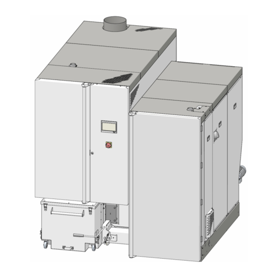
Summary of Contents for SOLARFOCUS maximus 150
- Page 1 Commercial boiler maxi mus Operation manual for qualified personnel Read carefully before operating. DR-0160-EN / v4b-201903...
-
Page 2: Table Of Contents
1 About this manual Content 1 About this manual 8.5 Connect additional components (on site) 8.6 Cable ducts on the boiler 2 Safety information 8.7 Sensor resistance table 8.8 Connecting the control to the internet 3 Standards, guidelines, regulations 9 Installing the intermediate pellet store 4 Product information 4.1 Fuel 10 Initial start-up... -
Page 3: Safety Information
– System may only be serviced and put into ope- – VDI 2035 - Preventing scale formation in hot water ration by certified qualified personnel (SOLARFOCUS service technician or heating and hot water warming systems SOLARFOCUS service partner. – DIN EN 12828 Heating systems in buildings - plan-... -
Page 4: Product Information
4 Product information Austria 4 Product information – TRV B H 118 -Technical guidelines for preventive fire protection – ÖNORM H 5170 - Heating systems - requirements for construction and safety technology as well as for fire and environmental protection – ÖNORM H 5195-1 - Heat transfer media for buil- ding services systems, Part 1: Preventing damage from corrosion and scale formation in closed hot water heating systems... -
Page 5: Safety Devices
2 Safety information After tripping, the STL must be manually released 4.2 Safety devices again by unscrewing the black sealing cap and pres- sing the button as soon as the boiler temperature falls Heat dissipation below 60°C. – This function of the boiler control is a safety device If the safety overtemperature reset trips, this is indi- that prevents overheating of the boiler. - Page 6 2 Safety information EMERGENCY OFF switch Automatically triggered extinguishing device (ATED) – The EMERGENCY OFF switch is a manually ope- rated safety device. The burner and the fuel supply to the boiler are stopped. Circulation pumps remain in operation to dissipate heat and cool the boiler. –...
-
Page 7: Dimensions
2 Safety information – This device consists of an empty pipe with a mini- Safety switch on the channel cover mum nominal size of DN 20 and is to be installed in the fuel storage as specified by the manufacturer of the firing system directly above the delivery line in front of the wall or ceiling passage in such a way that the greatest possible success can be achie-... - Page 8 2 Safety information Top view Front Operation manual maximus...
-
Page 9: Functional Components, Combustion Principle
2 Safety information 4.4 Functional components, combustion principle Burner Fig. 2-6 Functional components Rotary valve Ash extraction burner Secondary air opening Feeder unit Ash container 10 Combustion chamber temperature sensor Push grate Primary air opening 11 Flue gas recirculation line Ash scraper Primary air outlet Fuel path... - Page 10 2 Safety information Heat exchanger Fig. 2-7 Functional components 13 Ash container 15 Ash extraction heat exchanger 14 Electrostatic separator 16 Heat exchanger Ash path – The ashes falling on the feed grate are transported from the transverse ash auger into the ash container 13. –...
-
Page 11: Technical Specifications
2 Safety information 4.5 Technical specifications maxi Wood chips output [kW] Pellets output [kW] Boiler class (acc. to EN 305:5 2012) Dimensions Width [cm] Height incl. adjustable feet [cm] Depth with ID fan [cm] Burner insertion dimension [cm] (width) Heat exchanger insertion dimen- [cm] sion (width) Minimum room height... - Page 12 2 Safety information maxi Emissions according to test report: Wood chips Flue gas value from test 18-IN-AT-UW-OÖ- 18-IN-AT-UW-OÖ- Interpolation accor- report: EX-205/3 EX-205/4 ding to EN 303-5 TÜV Austria TÜV Austria Test institute / test report no. CO full load [mg/m³] CO Partial load [mg/m³] full load [mg/m³]...
-
Page 13: Prior To Assembly
5 Prior to assembly ► Secure the heat exchanger at four metal eyelets 5 Prior to assembly Consult a competent chimney sweep ► Secure the burner at both metal eyelets 1. before connecting the heating system. He must approve the installation and is the contact person regarding technical and legal issues. -
Page 14: Chimney, Flue Gas Pipe
5 Prior to assembly Supply air/exhaust air in Boiler room 5.3 Chimney, flue gas pipe For Austria (according to standard H 5170): – For the supply air, 2 cm² per kW thermal output of the fuel, but allow at least 200 cm² free cross-sec- tion. - Page 15 5 Prior to assembly Execution of the flue gas pipe Install explosion damper – Run the flue gas pipe towards the chimney in a short and rising direction, with as few chan- Fig. 2-10: Explosion damper integrated into draught limiter ges of direction as possible. Before longer horizontal pipe sections –...
-
Page 16: Installation
6 Installation 6.1.1 Adjust spacing screws 6 Installation ► The two lower holes serve to receive the spa- cing adjustment screws. 6.1 Mount heat exchanger on the burner Fig. 2-12: Hole for screws This chapter describes how to make the necessary connections between the heat exchanger and the bur- ►... -
Page 17: Screw On Flue Gas Pipe Flange
6 Installation 6.1.2 Screw on flue gas pipe flange ► Mount Auger channel on the heat exchanger. ► Connect the flange of the flue gas pipe with 6 pcs. hexagonal screws and nuts. Fig. 2-16: Mount the auger channel ► Slide metal rings and 2, and gasket onto the Fig. -
Page 18: Connect Flue Gas Recirculation Line
6 Installation ► Mount the auger channel onto the burner with 4 ► Dismantle cover pcs. hexagonal screws. ► Fix auger shaft into the receptacle with hexa- gonal screw and hex nut. Fig. 2-19: Mount the auger channel Fig. 2-22: Connect the auger shaft ►... -
Page 19: Connect Burner And Heat Exchanger Hydraulically
6 Installation 6.1.5 Connect burner and heat exchanger 6.3 Mount feeder grate drive hydraulically ► Mount drive unit (plate, housing, motor/gearbox) to the burner with 4 pcs hexagonal screws. ► Make piping between the two connections. ► Mount connecting rod with washer and circlip on (Connection is not pre-fabricated). -
Page 20: Install The Feeder Unit
6 Installation Connect the feeder motor 6.4 Install the feeder unit ► Connect the pre-routed cable as shown in the ter- ► Mount the feeder unit including installed rotary minal area of the motor. valve, to the burner with 4 pcs. hexagonal screw; enclose seal 2. -
Page 21: Install Thermal Overload Protection
6 Installation ► Fit the thermal overload protection in the direction 6.7 Install thermal overload protection of flow as seen before the safety heat exchanger CAUTION (i.e. no water pressure building up in the heat – Only standard-tested thermal overload pro- exchanger). -
Page 22: Fill The Heating System
6 Installation Exhaust pipe vertical 6.9 Fill the heating system The filling can be done via the drain connection > 25 the boiler. This is placed on the back of the heat exchanger. 6.10 Bleed the heating system Boilers of the series maxi have no vent valves installed in the boiler. -
Page 23: Mount Cladding On The Boiler
7 Hydraulic connection Latch in ash container 7 Hydraulic connection ► Press lever down to the stop. The ash container is thereby pressed against the auger channel. 7.1 General information Provide sufficient shut-off options Position shut-off valves for each section (in buffer tank, etc.) in order to minimise the quantity of water that needs to be replaced in the event of repairs or sys- tem extensions... -
Page 24: Boiler Connections
2 Boiler temperature sensor The use of a return booster module is a pre- 3 Sensor for overtemperature reset button (STB) requisite for SOLARFOCUS warranty and gua- rantee claims. Return flow sensor, pressure transmitter 7.2 Boiler connections Boiler flow, boiler return Fig. -
Page 25: Make-Up Water Requirements
6 Installation Boiler draining The fill and make-up water should meet the following guideline values a ccording to VDI 2035 Part 1. Specific system volume (VDI 2035) Total heat <20 ≥20 <50 ≥50 output l/kW l/kW l/kW < 50 kW ≤... -
Page 26: Electrical Connection
8 Electrical connection Components (circuit boards,...) in the control cabi- 8 Electrical connection DANGER - There is a risk of fatal electric shocks when working on electrical components of the system – Work may be performed only by a qualified electrician. -
Page 27: Voltage Supply For The Heating System
8 Electrical connection Designation Connection Designation Connection Direct extraction 1(RA1): Thermal contact X9.1-X9.2 Return booster pump X4.4-X4.6 + safety switch Return mixer A1:X13 Direct extraction 2(RA2): Thermal contact X9.3-X9.4 Return sensor > 24 A1:X32 + safety switch Rotary drive for flue gas booster >... -
Page 28: Connect Components To The Control Cabinet (On Site)
8 Electrical connection 8.4.3 Connect combustion chamber tem- 8.4 Connect components to the control perature sensor cabinet (on site) For the following four components, the pre-wiring on ► Connect combustion chamber temperature sen- the burner is present (the cables are in pre-routed in to A2:X11 cable duct 1 >... -
Page 29: Connect Rotary Actuators
8 Electrical connection 8.4.5 Connect rotary actuators Terminal X200 (rotary drive for primary air) The bus cables coming from the control cabinet (clam- ping area X10) of the heat exchanger include the fol- lowing components when fully installed: – Rotary drive for primary air >... -
Page 30: Connect Additional Components (On Site)
External boiler request (A1:X28) Potential-free Relay output for switching an external boiler, for example, an external boiler is controlled by the SOLARFOCUS boiler control CAUTION – The connection is floating and has a maximum load of 5A. Operation manual maximus... -
Page 31: Cable Ducts On The Boiler
CAUTION – The connection is floating and has a maximum load of 5A. External request (A1:X51) Fig. 2-50: Burner rear Input, i.e., the SOLARFOCUS boiler can be started by an external control. 8.7 Sensor resistance table CAUTION–The connection must be floating. -
Page 32: Connecting The Control To The Internet
9 Installing the intermediate pellet store 8.8 Connecting the control to the internet 9 Installing the intermediate pel- manager- To enable the Internet connection of the eco let store touch boiler control, connect the Ethernet port X2 (type RJ45) on the bottom of the display by cable to a net- Connect angle compensation work router. -
Page 33: Initial Start-Up
► Carry out the commissioning routine in the boiler control. After having completed initial commissioning, Fig. 2-56: Intermediate pellet store the completed commissioning form should be returned to SOLARFOCUS. If this does not 1 Pellet suction turbine X4.13-X4.15 happen, then for guarantee and warranty 2 Filling level sensor... -
Page 34: Annex
11 Annex 11 Annex 11.1 Boiler covers - overview Fig. 2-58 Fig. 2-59 Operation manual maximus... -
Page 35: Boiler Power Element, Circuit Boards
11 Annex 11.2 Boiler power element, circuit boards Boiler power element_A1 Fig. 2-60 Circuit board_A2 Circuit board_A3 (or optional circuit board_A4) Fig. 2-61 Fig. 2-62 Circuit board_A3 = Direct Extraction 1 Circuit board_A4 = Direct Extraction 4 Operation manual maximus... -
Page 36: Electrical Components: Overview
11 Annex Heat exchanger: Top side 11.3 Electrical components: Overview The components listed below are factory-installed and -connected, i.e. no assembly/installation work is requi- red on site. The information given here is intended to contribute to a better understanding or facilitate the locating of com- ponents in the event that they need to be replaced. -
Page 37: Connect Pellet Hose
'floating' upwards (in the case of floor-mounting, e.g. suction head). – Route hose as straight as possible. To avoid sag- ging of SOLARFOCUS articles, use a support shell made of zinc-plated sheet steel. – Do not kink the hose (observe bending radius of >... -
Page 38: Delivery Systems (Pellets, Wood Chips)
11 Annex Mole suction system 11.5 Delivery systems (pellets, wood chips) Pellets Suction heads and diverter for suction heads manual or automatic Fig. 2-70 1 Container auger motor > 33 (=direct extraction motor 1), connection A3:X2 2 Connect mole to A1: X14, the parameter in the manufacturer's manual is called Boiler request (mole is unlike direct extraction motor 2) Fig. - Page 39 11 Annex Direct extraction with articulated arm agitator Fig. 2-72 1 Direct extraction auger motor (=direct extrac- tion motor 1), connection A3:X2 2 Bunker filling auger motor (=direct extraction motor 2), connection A4:X2 Direct extraction by downpipe Fig. 2-73 1 Direct extraction auger motor (=direct extrac- tion motor 1), connection A3:X2 Operation manual maximus...
- Page 40 makes you independent Innovative products to spare the environment and your wallet! Quality made in Austria Biomass heating - Solar systems - Heat pumps - Fresh water equipment Tested state-of-the-art technology – EN ISO 9001 certified Austria...
Need help?
Do you have a question about the maximus 150 and is the answer not in the manual?
Questions and answers