
Related Manuals for Dahua ECA3A1


Summary of Contents for Dahua ECA3A1
- Page 1 Installation Manual Ex-mark: Exdb ⅡC T6 Gb/ Ex tb IIIC T80°C Db Explosion-Proof IR Camera (ECA3A1) Installation Manual Installation Manual V1.0.0 ZHEJIANG DAHUA VISION TECHNOLOGY CO., LTD. V1.0.1...
-
Page 2: Foreword
Installation Manual Foreword General This manual introduces the structure and installation of the Explosion-Proof IR Camera (hereinafter referred to as "the Camera"). Figures in this manual are only for reference, and the actual product shall prevail. Safety Instructions The following categorized signal words with defined meaning might appear in the manual. Signal Words Meaning Indicates a high potential hazard which, if not avoided, will result... - Page 3 Installation Manual contact the customer service for the latest program and supplementary documentation. There still might be deviation in technical data, functions and operations description, or errors in print. If there is any doubt or dispute, please refer to our final explanation. Upgrade the reader software or try other mainstream reader software if the manual (in PDF ...
-
Page 4: Important Safeguards And Warnings
Installation Manual Important Safeguards and Warnings The manual will help you to use the Camera properly. Read the manual carefully before using the Camera, and keep it well for future reference. Power Requirements Make sure that the power supply conforms to the requirements on the nameplate before ... - Page 5 Installation Manual power cable immediately if there is water or other liquid falling into the Camera. And contact your local retailer or after-sale service center. Avoid seawater or rain eroding the Camera. Avoid the lens aiming at intense light source, including sunlight, and incandescent light; ...
- Page 6 Installation Manual Storage Requirements The warehouse should be well ventilated and free from corrosive gases; the ambient temperature should be -40°C to 55°C; the relative humidity should be no more than 85%; there should be no strong mechanical vibration, impact or strong magnetic field. Keep the Camera away from fire source, and do not store it with corrosive, inflammable and ...
-
Page 7: Table Of Contents
Installation Manual Table of Contents Foreword ................................I Important Safeguards and Warnings ......................III 1 Packing List ..............................1 2 Overview ................................ 2 Introduction ....................................2 Application ....................................2 Appearance ....................................2 Explosion-Proof Structure ............................... 2 Dimensions ....................................4 Mechanical Specification ................................ 4 Electric Specification ................................. -
Page 8: Packing List
Installation Manual Packing List Check the Camera and accessories in the packing box carefully after unpacking. If any discrepancy or anything is missing, contact local supplier or customer service center. The product is subject to change without further notice. If there is any question or dispute, refer to our final explanation. Figure 1-1 Packing list Name... -
Page 9: Overview
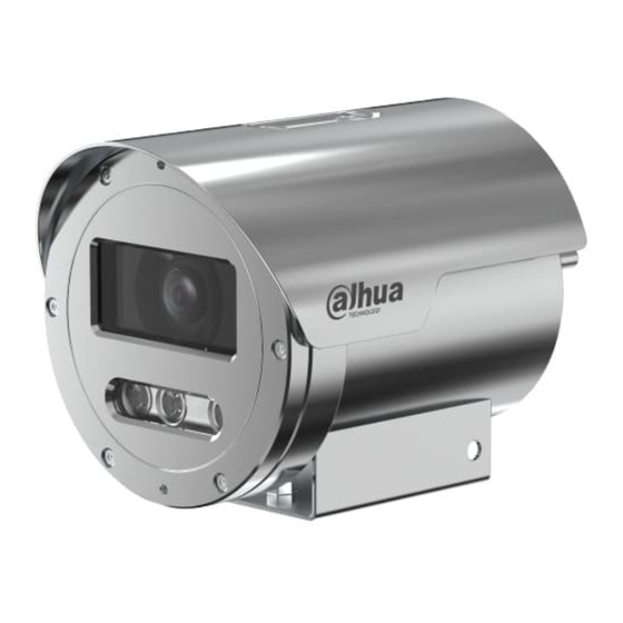
Installation Manual Overview Introduction As a new generation of explosion-proof monitoring device, the Camera adopts advanced manufacturing technique and new design. It is integrated with clear image, digitization, intelligence, and easy installation. After installing the Camera, the overall aesthetics of the monitoring site is not affected. - Page 10 Installation Manual After the welding and finish machining, the enclosure can sustain the severe hydrostatic test. With test pressure 1.85Mpa and the duration 10 seconds to 12 seconds, there is no water dripping and transformed structure. When the Camera is working normally, the maximum surface temperature of the enclosure is no ...
-
Page 11: Dimensions
Installation Manual Dimensions Figure 2-3 Dimensions (mm [inch]) Mechanical Specification Table 2-2 Mechanical specification Parameter Description Material Stainless steel 304 by default; stainless steel 316L customizable IP rating IP68 Cable outlet hole Cable outlet hole thread 1 G3/4 internal thread Installation Wall mount Electric Specification... -
Page 12: Environment Requirements
Installation Manual Table 2-3 Electric specification Parameter Description Input voltage DC 12V or PoE (AF standard) Maximum current ≤ 1.5A Power consumption ≤ 12 W Electrical connection There are power, network and audio ports on the control cable by default. A flexible cube is needed to connect these ports. Environment Requirements Table 2-4 Environment requirements Parameter... -
Page 13: Installation
Installation Manual Installation Before installing the Camera, pay attention to the following instructions. Make sure that there is no obvious damage of the Camera, and the accessories are complete. Do not disassemble the Camera randomly. Operate it in accordance with the manual. ... -
Page 14: Connecting Cable And Flexible Tube
Installation Manual Connecting Cable and Flexible Tube 3.2.1 Cable Description Before leaving the factory, a composite cable is connected to the Camera. The cable threads out from the outlet hole at the camera rear and it is 1.5 m by default. When in use, the cable needs to be covered with a 1-meter-long explosion-proof flexible tube, and then led into explosion-proof control cabinet to connect to the system bus. - Page 15 Installation Manual Table 3-3 Connecting component (1) Description Description Explosion flexible tube Outlet hole Step 2 Tighten the thread connector and then the explosion flexible tube. Keep the silicone ring and metal gasket provided with the Camera properly for further use. Figure 3-3 Connecting component (2)
-
Page 16: Installing The Camera
Installation Manual Table 3-4 Connecting component (2) Description Description Explosion flexible tube Metal gasket Thread connector Silicone ring Installing the Camera 3.3.1 Precautions Choose a proper hole location for the bracket and use high-quality expansion bolts to fix the bracket. - Page 17 Installation Manual Figure 3-5 Fix the camera Step 3 Connect the cables among the Camera, bracket, flexible tube and control cabinet. Figure 3-6 Installation and cable layout...
- Page 18 Installation Manual Table 3-5 Installation and cable layout Description Wall 4 M6 expansion screws used to fix the bracket on the wall Wall mount bracket Flexible tube Junction box Flexible tube Galvanized steel pipe connected to the terminal...
-
Page 19: Troubleshooting
Installation Manual Troubleshooting For some common issues, you can solve them through the following solutions. Malfunction Reason Solution Check whether the power Power supply disconnected. supply is normal. No image on the web Video signal cable is in poor Check whether the video signal contact. -
Page 20: Appendix 1 Thunder-Proof And Surge Protection
Installation Manual Thunder-Proof and Surge Protection Appendix 1 Appendix 1.1 Install Lightning Protection Devices Outdoors Transient voltage suppressor (TVS) is applied to protect the Camera against voltage spikes and overvoltage below 6000V. However, it is still necessary to take safeguard measures when installing the Camera according to your local electrical safety regulations. - Page 21 Installation Manual Description Communication lightning conductor. Power supply lightning conductor. Impedance of the cable connected to the ground wire should be less than 4Ω. The radius is 60 m. Lightning conductor. Steel tube. Appendix Figure 1-2 Install lightning protection devices (2) R: The radius of the circle, and R=60 m;...
-
Page 22: Appendix 1.2 Install Lightning Protection Devices Indoors
Installation Manual Appendix 1.2 Install Lightning Protection Devices Indoors You shall use multiple copper cables whose cross-sectional area are not less than 25 mm to connect the yellow-green ground cable/ground screws to the indoor equipotential earthing terminals. Appendix Figure 1-3 Install lightning protection devices indoors Appendix Table 1-2 Name Yellow-green grounding cable... -
Page 23: Appendix 2
Installation Manual Cable Diameter (12V DC) and Appendix 2 Transmission Distance The recommended transmission distances are for reference only, and the actual conditions shall prevail. The following table gives the maximum transmission distance of cables with certain diameters when the 12V DC voltage loss rate is below 10%. -
Page 24: Appendix 3 Wire Gauge Reference Sheet
Installation Manual Wire Gauge Reference Sheet Appendix 3 Metric Bare Wire Bare Wire Cross Diameter (mm) Section Area (mm 0.050 0.00196 0.060 0.00283 0.070 0.00385 0.080 0.00503 0.090 0.00636 0.100 0.00785 0.110 0.00950 0.130 0.01327 0.140 0.01539 0.160 0.02011 0.180 0.02545 0.200 0.03142... -
Page 25: Appendix 4 Cybersecurity Recommendations
Installation Manual Cybersecurity Recommendations Appendix 4 Cybersecurity is more than just a buzzword: it’s something that pertains to every device that is connected to the internet. IP video surveillance is not immune to cyber risks, but taking basic steps toward protecting and strengthening networks and networked appliances will make them less susceptible to attacks. - Page 26 Installation Manual We suggest you to change default HTTP and other service ports into any set of numbers between 1024~65535, reducing the risk of outsiders being able to guess which ports you are using. Enable HTTPS We suggest you to enable HTTPS, so that you visit Web service through a secure communication channel.
- Page 27 Installation Manual Establish the 802.1x access authentication system to reduce the risk of unauthorized access to private networks. Enable IP/MAC address filtering function to limit the range of hosts allowed to access the device.
Need help?
Do you have a question about the ECA3A1 and is the answer not in the manual?
Questions and answers