Sign In
Upload
Manuals
Brands
Rohde & Schwarz Manuals
Receiver
890 Series
Rohde & Schwarz 890 Series Manuals
Manuals and User Guides for Rohde & Schwarz 890 Series. We have
1
Rohde & Schwarz 890 Series manual available for free PDF download: User Manual
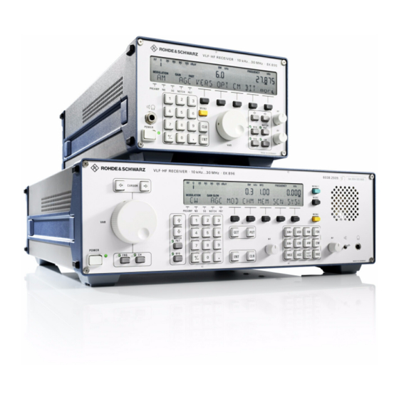
Rohde & Schwarz 890 Series User Manual (406 pages)
VLF-HF Receivers
Brand:
Rohde & Schwarz
| Category:
Receiver
| Size: 21 MB
Table of Contents
Characteristics
23
Table of Contents
23
Application
27
Design and Functioning
28
Design of VLF>HF Receiver R&S EK 895
28
Design of VLF>HF Receiver R&S EK 896
30
Functioning
32
Design and Functioning of Modules
33
Frame
33
Control Unit (R&S EK 896), Block Diagram
39
Processor, Block Diagram
41
Synthesizer, Block Diagram
43
HF Unit, Block Diagram
45
Power Supply, Block Diagram
47
Preselection R&S FK 890H1 (Option), Block Diagram
53
BCD Interface R&S GC 890 (Option), Block Diagram
54
TTY Line Current Source R&S GH 890 (Option), Block Diagram
55
IF Converter R&S UX 895 (Option), Block Diagram
56
Block Diagram
57
Preparation for Use
67
Safety Notes
71
Unpacking and Checking
71
Control Unit (R&S EK 896)
72
IF / AF Processor
72
Operating Functions Set Ex Works
72
Power Supply
72
Processor
72
Synthesizer
72
TTY Line Current Source R&S GH 890 (Option)
72
General
73
Installation
73
Installation into a 19" Rack
74
Preparations
74
Installation of a Single Receiver R&S EK 895 with
75
Installation of Two Receivers R&S EK 895 with Parts Set R&S KA 890L1
76
Installation of One Receiver R&S EK 896 with
77
Table of Contents
111
Control Unit 2 ∫LOCAL∫ (R&S EK 895, = Option 'Control Unit R&S GB 890') or Control Unit (R&S EK 896)
117
General
117
Operation
117
Display
119
Frequency Scanning
120
Manual
120
Operating Modes
120
Channel
121
Channel Scanning
121
CHANNEL SCANNING with Freely Programmable Channel List
121
Software
121
Switching off
122
Switching on
122
Altering the Frequency with the Tuning Knob
124
Altering the Tuning Knob Stepwidth with the Cursor Control Keys
124
Entering a Frequency
124
Frequency
124
Modulation Mode
126
Modulation Mode Menu (R&S EK 895)
126
Modulation Mode Menu (R&S EK 896)
128
Selecting the Modulation Mode (R&S EK 896)
128
Demodulation Parameter Menu
130
Modulation Mode Menu (Data Link)
133
Bandwidth
134
Selecting a Bandwidth (R&S EK 895)
134
Altering the Bandwidth Quasi>Continuously or Selecting a Fixed Bandwidth (R&S EK 895)
136
Altering the Bandwidth Quasi>Continuously or Selecting a Fixed Bandwidth (R&S EK 896)
136
Altering the Frequency Offset or the Filter Frequency by Using the Step Keys (R&S EK 896)
140
Passband Tuning and Notch Filter
140
Control Type
142
Control Type Menu (R&S EK 895)
142
Selecting the Control Type (R&S EK 896)
142
Entering a DGC Value
144
Setting the Control Voltage
144
Control Time
146
Control Time Menu
146
Altering the BFO Frequency by Using the Step Keys (R&S EK 896)
148
Altering the BFO Frequency by Using the Tuning Knob (R&S EK 895)
148
Altering the Tuning Knob Stepwidth
148
BFO Frequency
148
Entering the BFO Frequency
148
Inverting the BFO Frequency
148
Calling up a Channel
150
Channel
150
Channel Scanning by Using the Tuning Knob
150
Clearing a Particular Channel
152
Clearing All Channels
152
Storing and Clearing
152
Storing into a Particular Channel
152
Storing into the Next Free Channel
152
Editing the Channel Contents
154
Entering the Digital Threshold
154
Inhibiting a Channel
154
Reactivating a Channel
154
Programming a Frequency Scanning Process
156
Scanning
156
Starting Channel Scanning (Ascending Channel Number Sequence)
156
Starting Channel Scanning (Freely Programmable Channel List)
156
Starting Frequency Scanning
156
Stopping or Resuming Channel Scanning
156
Clearing a Channel List
158
Programming a Channel Scanning Process (Ascending Channel Number Sequence)
158
Programming a Channel Scanning Process (Freely Programmable Channel List)
158
Altering the Stepwidth of the Tuning Knob
160
Disabling the Tuning Knob
160
Enabling the Tuning Knob
160
Special Functions
160
Disabling the Level Control for PZG Line
162
Disabling the Syllabic Control for PZG Line
162
Enabling the Level Control for PZG Line and / or
162
Enabling the Level Control for PZG Line, Extended Function
162
Enabling the Syllabic Control for PZG Line and / or
162
Activating the Default Value Setting
164
Calling up the Serial>Interface Setting
164
Enabling Local Control
164
Inhibiting Local Control
164
Inhibiting the Default Value Setting
164
Selecting the Bargraph Mode (R&S EK 895)
166
IF Processor R&S GM
168
Indicating Installed Options
168
Indicating the CM Status
168
Indicating the Software Version
168
Initiating the BIT and Indicating the BIT Status
168
System Functions
168
Inhibiting Fixed>Channel Operation
170
Initiating a System Reset
170
Linking Signal BYPASS to the Scanning Status
170
Setting Signal BYPASS to High Level
170
Setting Signal BYPASS to Low Level
170
Switchover to Fixed>Channel Operation
170
IF Menu
172
Fast Switchover of Bargraph Function (Level/Tuning Indication)
174
Separate Functions 1
174
Switching the Noise Blanker on or off
176
Switching the Notch Filters on or off
176
Switching the Preamplifier on or off
176
Switching the Squelch Function on or off
176
Separate Functions 2 (R&S EK 896)
177
Activating the Digtally Tuned RF Selector R&S FK 896D (Option)
178
Calling up the Buffer Contents
178
Deactivating the Digtally Tuned RF Selector R&S FK 896D (Option)
178
Selecting the Bargraph (R&S EK 896)
178
Selecting the USB Rx Filter Mode (R&S EK 896)
178
Starting or Stopping Scanning
178
Storage into the Buffer
178
Switching Remote Control off
178
Altering the Slave Address
180
Calling up the Slave Receiver Setting
180
Master / Slave Operation (R&S EK 895)
180
Transferring the Master Receiver Setting
180
Calling up the Slave Receiver Setting
182
Master / Slave Operation (R&S EK 896)
182
Programming a Slave Address
182
Transferring the Master Receiver Setting
182
Selecting Level Squelch And/Or Altering Level Squelch Threshold
184
Selecting Level/Syllabic Squelch
184
Selecting Syllabic Squelch And/Or Altering Syllabic Squelch Threshold
184
Squelch Type Setting
184
Adjusting the Volume
186
Loudspeaker (R&S EK 896)
186
Switching the Loudspeaker off
186
Switching the Loudspeaker on
186
Control Unit 1 ∫REMOTE∫ (R&S EK 895)
187
General
187
Switching on
187
Switching off
188
Maintenance and Troubleshooting
225
Cleaning
229
General
229
Maintenance
229
Retouching Paint Blemishes
229
CM Messages
230
Lists of Faults
230
Troubleshooting
230
BIT Messages
231
Fault Recognition through Switch>On
232
Troubleshooting with Control Unit 2 ∫LOCAL∫ (R&S EK 895, = Option 'Control Unit R&S GB!890') or Control Unit (R&S EK 895)
232
Automatic Fault Recognition During Operation
235
Fault Recognition During Operation by Inquiry of the CM Status
237
Fault Recognition During Operation by Initiation of the BIT
238
Troubleshooting with Control Unit 1 ∫REMOTE∫ (R&S EK 895 Only)
243
Troubleshooting with a Computer
247
Automatic Gain Control
248
Preparations
248
Required Test Equipment
248
Sensitivity
248
Signal>To>Noise Ratio
248
Simple Measurements
248
Preparations
250
Replacement of Modules
250
Control Unit 1 ∫REMOTE∫ (R&S EK 895)
251
Control Unit 2 ∫LOCAL∫ (R&S EK 895,= Option 'Control Unit R&S GB 890')
252
Control Unit (R&S EK 896)
253
Processor
254
Replacement of Back>Up Battery
254
Synthesizer
255
HF Unit
256
Power Supply
257
IF / AF Processor
258
TTY Line Current Source R&S GH 890
259
BCD Interface R&S GC 890
260
Filter
260
Interface
260
Preselection R&S FK 890H1
261
IF Converter R&S UX 895
262
IF Processor R&S GM 893
263
4.3.15 Digitally Tuned RF Selector R&S FK 896D
264
Adapter
264
Digital Selection
264
Interface
264
A1. Settings
285
A1. Settings
287
A1.1 Preparations
287
A1.2 Altering the Operating Voltage
288
A1.3 Use of an External Frequency Standard
289
A1.4 Setting the RS232C > RS485 Interface Parameters
290
A1.5
292
A1.6 Setting the AF Output Level
293
A1.6.1
293
A1.6.2
293
Procedure
293
Required Test Equipment
293
A1.7 Altering the Type of Current (Single Current Double Current, Option)
294
A1.8 Setting the AF2 Output Level
295
A1.8.1
295
A1.8.2
295
Procedure
295
Required Test Equipment
295
A2. External Interfaces
319
A2. External Interfaces
321
Antenna Connection
321
Headphone Connection (EK 896, Rear)
321
Frequency Standard Connection
322
FET Analyzer Connection
323
Spectrum Display Connection (Option)
324
Data Line Connection (AF and FSK Signals)
325
Control Line Connection (RS232C > RS485)
326
A3. Remote Control
337
A3.1 General
341
Manual
342
Operating Modes
342
Channel
343
Channel Scanning
343
CHANNEL SCANNING with
343
Freely Programmable Channel List
343
Frequency Scanning
343
Basic Settings
344
BFO Frequency
344
Frequency
344
Modulation Mode
345
A3.3.4
346
Bandwidth (R&S EK 895)
346
A3.3.5
347
Control Time
348
Control Type
348
DGC Value
349
Frequency Scanning
351
Resume Frequency Scanning
351
Start Frequency Scanning
351
Stop Frequency Scanning
351
Frequency Scanning Parameters
352
Digital Level Threshold
353
Dwell Time
353
Hold Time
354
Programming Example
355
Channel Scanning
356
Resume Channel Scanning
356
Start Channel Scanning
356
Stop Channel Scanning
356
A3.5.4
357
Channel Scanning Parameters
357
Dwell Time
358
Hold Time
358
A3.5.7
359
Programming Example
359
A3.6 Channel Scanning with Freely Programmable Channel List
360
Resume Channel Scanning
360
Start Channel Scanning
360
Stop Channel Scanning
360
Channel List
361
A3.6.6
362
Hold Time
362
Programming Example
363
Special Functions
364
Inquiry of PZG Line Status
365
Passband Tuning
365
Inhibiting or Enabling the Level Control for PZG Line
366
Setting the Level Threshold
366
Inhibiting or Enabling the Syllabic Control for PZG Line
367
Setting the Syllabic Squelch Threshold
367
Initiation of BIT and / or Inquiry of BIT Status
368
Inquiry of CM Status
368
Inquiry of Receive Level
368
A3.7.10
369
A3.7.11
369
A3.7.12
369
Editing the Channel Contents
369
A3.7.13 Inquiry of Channel Contents
370
A3.7.14
371
A3.7.15
371
Inhibiting a Channel
371
Reactivating a Channel
371
A3.7.16 Master / Slave Operation
372
A3.7.17
372
A3.7.18
373
A3.7.19 Switching the Noise Blanker on or off
373
Switching the Digital Selection on or off
373
A3.7.23 Switching the Preamplifier on or off
375
A3.7.24
375
A3.7.25 Enabling or Disabling the Default Setting
375
A3.7.25.1
376
A3.7.26
376
Default Settings
376
Inquiry of Receive Level (Extended)
376
Addressed Operation
377
System Functions
377
Inquiry of if Filter Bandwidths
378
Inquiry of Software Version
378
Inquiry of Options
379
Signal BYPASS
379
Inquiry of Operating Status
380
Inquiry of Scanning Status
380
Initiating a Reset
381
Inquiry of Error Status
381
A3.8.10 Activating Command if
382
A3.8.11 Enabling or Disabling Local Control
382
A3.8.12
383
Inquiry of Software and DSP Version
383
A3.9 List of Commands
384
Advertisement
Advertisement
Related Products
Rohde & Schwarz 802.2020.52
Rohde & Schwarz 802.2020.54
Rohde & Schwarz 827.6513.06
Rohde & Schwarz 851800832
Rohde & Schwarz 801.0001.52
Rohde & Schwarz 1142.8007.03
Rohde & Schwarz 1142.8007.07
Rohde & Schwarz 1300.5001K03
Rohde & Schwarz 1300.5001K06
Rohde & Schwarz 1300.5001K13
Rohde & Schwarz Categories
Measuring Instruments
Test Equipment
Portable Generator
Power Supply
Accessories
More Rohde & Schwarz Manuals
Login
Sign In
OR
Sign in with Facebook
Sign in with Google
Upload manual
Upload from disk
Upload from URL