Table of Contents
Advertisement
HARBOR BREEZE and logo design are
trademarks or registered trademarks of
LF, LLC. All rights reserved.
Purchase Date
Questions, problems, missing parts? Before returning to your retailer, call our customer
service department at
also contact us at partsplus@lowes.com or visit www.lowespartsplus.com.
AS21351
1-888-251-1003, 8 a.m. - 8 p.m., EST, Monday - Sunday. You could
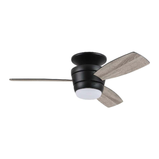
MAZON CEILING FAN
1
ITEM #0807421
0807422
2599776
2807158
MODEL #MZ44BNK3LR
MZ44ORB3LR
MZ44WW3LR
MZ44MBK3LR
Español p. 18
ATTACH YOUR RECEIPT HERE
ADJUNTE SU RECIBO AQUÍ
4007498
Advertisement
Table of Contents

Related Manuals for Harbor Breeze MAZON MZ44MBK3LR


Summary of Contents for Harbor Breeze MAZON MZ44MBK3LR
- Page 1 ITEM #0807421 0807422 2599776 2807158 MAZON CEILING FAN HARBOR BREEZE and logo design are MODEL #MZ44BNK3LR trademarks or registered trademarks of MZ44ORB3LR LF, LLC. All rights reserved. MZ44WW3LR MZ44MBK3LR Español p. 18 ATTACH YOUR RECEIPT HERE ADJUNTE SU RECIBO AQUÍ...
-
Page 2: Table Of Contents
TABLE OF CONTENTS Safety Information .........................2 Package Contents .........................5 Hardware Contents .......................6 Preparation ..........................6 Initial Installation ........................6 Wiring ............................9 Final Installation ........................10 Operating Instructions ......................13 Care and Maintenance ......................15 Troubleshooting ........................16 Limited Lifetime Warranty ....................17 Replacement Parts List .......................17 SAFETY INFORMATION Modifications not approved by the party responsible for compliance could void the user's authority to operate the equipment. - Page 3 SAFETY INFORMATION READ AND SAVE THESE INSTRUCTIONS • Do not discard fan carton or foam inserts. Should this fan need to be returned to the factory for repairs, it must be shipped in its original packaging to ensure proper protection against damage that might exceed the initial cause for return.
- Page 4 SAFETY INFORMATION WARNING To reduce the risk of fire, electrical shock or personal injury, do not bend the blades when installing or balancing them, or cleaning the fan. Do not insert objects between the rotating fan blades. To reduce the risk of personal injury, use ONLY parts provided with this fan. The use of parts OTHER than those provided with this fan will void the warranty.
-
Page 5: Package Contents
PACKAGE CONTENTS PART DESCRIPTION QUANTITY PART DESCRIPTION QUANTITY Mounting Plate LED Light Kit Canopy Ring Mounting Plate Lock Washer (preassembled) Motor Assembly Mounting Plate Screw Fitter Plate (preassembled) Shade Motor Plate Screw Fitter Plate Screw (preassembled) (preassembled) Remote Pack Blade IMPORTANT REMINDER: You must use the parts provided with this fan for proper installation and safety. -
Page 6: Hardware Contents
HARDWARE CONTENTS (shown actual size) Wire Blade Fiber Screw Connector Blade Washer Qty. 9 Qty. 3 + 1 extra + 1 extra Qty. 9 + 1 extra PREPARATION Before beginning assembly of product, make sure all parts are present. Compare parts with package contents list and hardware contents list. - Page 7 INITIAL INSTALLATION This fan can be mounted as a flushmount on a regular (no-slope) ceiling only. 30 in. Check to make sure blades (G) will be at least min. 30 inches from any obstruction and at least 7 ft. above the floor. 7 ft.
- Page 8 INITIAL INSTALLATION Locate mounting plate screw (J)/mounting plate lock washer (I) on outer edge of mounting plate (A) that is closest to the j-hook and remove that mounting plate screw (J)/mounting plate lock washer (I). Also, remove mounting plate screw (J)/mounting plate lock washer (I) on outer edge of mounting plate (A) directly opposite the one that was just removed.
-
Page 9: Wiring
WIRING WARNING: To reduce the risk of fire, electrical shock, or personal injury, wire connectors provided with this fan are designed to accept only one 12-gauge house wire and two lead wires from the fan. If your house wire is larger than 12-gauge or there is more than one house wire to connect to the corresponding fan lead wires, consult an electrician for the proper size wire connectors to use. -
Page 10: Final Installation
WIRING Wrap electrical tape around each individual wire connector (CC) down to the wire. WARNING: Make sure no bare wire or wire strands are visible after making connections. Place green and white connections on opposite side of box from the black and blue (if applicable) connections. - Page 11 FINAL INSTALLATION DANGER: To reduce the risk of serious bodily injury, DO NOT use power tools to assemble the blades (G). If screws are overtightened, blades (G) may crack and break. Insert the blade (G) through the slot on the band of the motor assembly (C).
- Page 12 FINAL INSTALLATION Locate BLUE and WHITE wires in fitter plate (D). Connect WHITE wire from LED light kit (H) to WHITE wire from fitter plate (D). Connect BLUE wire from LED light kit (H) to BLUE wire from fitter plate (D). Make sure molex connections are secure.
-
Page 13: Operating Instructions
OPERATING INSTRUCTIONS CAUTION: The remote control transmitter can be programmed to multiple receivers or fans. If this is not desired, turn wall switch off to any other programmable receiver or fan. FCC Compliance Notice for Remote Control Modifications not approved by the party responsible for compliance could void the user's authority to operate the equipment. - Page 14 OPERATING INSTRUCTIONS 2. Restore electrical power. Within 30 seconds of restoring electrical power, press and hold the “0” button on the remote control transmitter for 5 seconds or until light on the fan blinks twice. Use the remote control transmitter to test the light and fan functions to confirm the learning process is complete.
-
Page 15: Care And Maintenance
OPERATING INSTRUCTIONS 4a. In warmer weather, setting the reverse switch in the LEFT position will result in downward airflow creating a wind chill effect. 4b. In cooler weather, setting the reverse switch in the RIGHT position will result in upward airflow that can help move stagnant, hot air off the ceiling area. -
Page 16: Troubleshooting
TROUBLESHOOTING WARNING: Before beginning work, shut off the power supply to avoid electrical shock. PROBLEM POSSIBLE CAUSE CORRECTIVE ACTION Fan does not 1. Reverse switch not engaged. 1. Push switch firmly either left or move. right. 2. Power is off or fuse is blown. 2. -
Page 17: Limited Lifetime Warranty
LIMITED LIFETIME WARRANTY The distributor warrants this fan to be free from defects in workmanship and materials present at time of shipment from the factory for Lifetime limited from the date of purchase. This warranty applies only to the original purchaser. The distributor agrees to correct any defect at no charge or, at our option, replace the ceiling fan with a comparable or superior model.
Need help?
Do you have a question about the MAZON MZ44MBK3LR and is the answer not in the manual?
Questions and answers