Advertisement
Quick Links
www.ti.com
Design Guide: TIDA-010037
High-Accuracy Split-Phase CT Electricity Meter Reference
Design Using Standalone ADCs
Description
This reference design implements Class 0.1 split-
phase energy measurement using high-performance,
multi-channel analog-to-digital converters (ADC). The
ADC samples current transformers (CT) at 8 kHz to
measure the current and voltage of each leg of the AC
mains. The reference design achieves high accuracy
across a wide input current range (0.05–100 A) and
supports high sampling frequencies necessary for
power quality features such as individual harmonic
analysis. An ADC sample rate of 32 ksps can be
acheived by disabling some software functions.
Independent ADCs provide flexibility in the choice of
metrology microcontrollers compared to integrated
SoCs. This reference design uses a SimpleLink
ARM
®
Cortex
®
-M4 host microcontroller for metrology.
The necessary software functionality is implemented
in the ADC Energy Metrology library. The software
library can be compiled with Code Composer Studio
or IAR Embedded Workbench
Resources
TIDA-010037
ADS131M04,
MSP432P4111
TPS3840, TPS25921l,
THVD1500
ISO7731B,
TRS3232E
ADC Energy Metrology Library
Ask our TI E2E
TIDUEM8B – MARCH 2019 – REVISED FEBRUARY 2021
Submit Document Feedback
™
™
®
.
Design Folder
Product Folder
Product Folder
Product Folder
Software
™
support experts
Load
Phase A
Phase B
5V_IN
VCC
TPS709
GND
GND
TPS25921L
5V_LMT
TVS1800
VCC
RESET VCC
VDD
ADS131M04
GND
GND
TPS3840
CT
+
CT
I
A
6'
ADC
-
CSn
+
SCLK
CT
I
ADC
B
6'
DIN
-
DOUT
+
ADC
V
6'
A
-
DRDY
+
6'
ADC
V
B
-
CLKIN
Phase A
Phase B
Source From Utility
Copyright © 2021 Texas Instruments Incorporated
Features
•
Split-phase metrology for electricity meters that
meets ANSI C12.20 Class 0.1 active energy
accuracy requirements across 10000:1 input range
•
Active and reactive energy and power, root mean
square (RMS) current and voltage, power factor,
and line-frequency calculations
•
Isolated RS-232 and RS-485 with 5-kV
isolation
•
Communications module expansion with current
limit and overvoltage and undervoltage protection
•
Tested across 50 mA to 100 A input range
•
High active energy accuracy still obtained when
ADC sample rate increased to 32 ksps
•
Software for energy metrology and displaying
results on a Windows
Applications
•
Electricity meter
•
Power quality meter
•
Power quality analyzer
+
A
B
-
TOTAL
kWh
VCC
DVCC
Lx
Active
DVSS
GPIO
GND
ISO-DVCC
VCC
Reactive
GPIO
ISO-GND
ISO7720
VCC
ISO-ACTIVE
GND
ISO-REACTIVE
RESET
RST/NMI
MSP432P4111
GND
GPIO
SPI CLK
RS232_VCC
VCC
SPI MOSI
SPI MISO
RS232_GND
GND
TPS709
RGND
ISO7731 B
Interruptible GPIO
UART2 TX
TRS3232E
UART2 RX
GPIO
SMCLK
GND
Lx/PMAP GPIO
Board
RE
Lx/PMAP GPIO
Header to
RGND
WE
Lx/PMAP GPIO
External
VCC3
THVD1500
Lx/PMAP GPIO
Radio/Radio
Module
5V_LMT
High-Accuracy Split-Phase CT Electricity Meter Reference Design Using
Description
RMS
®
PC GUI.
DTR
RTS
RS-232
Connection
RS-485
Connection
Standalone ADCs
1
Advertisement

Related Manuals for Texas Instruments TIDA-010037


Summary of Contents for Texas Instruments TIDA-010037
- Page 1 Lx/PMAP GPIO Radio/Radio Connection Module 5V_LMT Phase A Phase B Source From Utility TIDUEM8B – MARCH 2019 – REVISED FEBRUARY 2021 High-Accuracy Split-Phase CT Electricity Meter Reference Design Using Submit Document Feedback Standalone ADCs Copyright © 2021 Texas Instruments Incorporated...
-
Page 2: System Description
High-Accuracy Split-Phase CT Electricity Meter Reference Design Using TIDUEM8B – MARCH 2019 – REVISED FEBRUARY 2021 Standalone ADCs Submit Document Feedback Copyright © 2021 Texas Instruments Incorporated... - Page 3 ADC can have its clock varied. TIDUEM8B – MARCH 2019 – REVISED FEBRUARY 2021 High-Accuracy Split-Phase CT Electricity Meter Reference Design Using Submit Document Feedback Standalone ADCs Copyright © 2021 Texas Instruments Incorporated...
- Page 4 Option 1: 3.3 V directly to DVCC rail; Option 2: 5V to J4 header High-Accuracy Split-Phase CT Electricity Meter Reference Design Using TIDUEM8B – MARCH 2019 – REVISED FEBRUARY 2021 Standalone ADCs Submit Document Feedback Copyright © 2021 Texas Instruments Incorporated...
- Page 5 Lx/PMAP GPIO External RS-485 VCC3 THVD1500 Lx/PMAP GPIO Radio/Radio Connection Module 5V_LMT Phase A Phase B Source From Utility Figure 2-1. TIDA-010037 Block Diagram, Two-Voltage Configuration Load Phase A Phase B 5V_IN TPS709 TPS25921L TVS1800 5V_LMT TOTAL DVCC RESET VCC ADS131M04...
- Page 6 Rogowski coil to measure current. High-Accuracy Split-Phase CT Electricity Meter Reference Design Using TIDUEM8B – MARCH 2019 – REVISED FEBRUARY 2021 Standalone ADCs Submit Document Feedback Copyright © 2021 Texas Instruments Incorporated...
- Page 7 PC GUI using either the isolated RS-232 or isolated RS-485 circuit of the board. The CRC module of the TIDUEM8B – MARCH 2019 – REVISED FEBRUARY 2021 High-Accuracy Split-Phase CT Electricity Meter Reference Design Using Submit Document Feedback Standalone ADCs Copyright © 2021 Texas Instruments Incorporated...
- Page 8 TPS25921L device, the current is limited by quickly opening it and triggering the FLT signal. This High-Accuracy Split-Phase CT Electricity Meter Reference Design Using TIDUEM8B – MARCH 2019 – REVISED FEBRUARY 2021 Standalone ADCs Submit Document Feedback Copyright © 2021 Texas Instruments Incorporated...
- Page 9 The RS-232 specification (when properly TIDUEM8B – MARCH 2019 – REVISED FEBRUARY 2021 High-Accuracy Split-Phase CT Electricity Meter Reference Design Using Submit Document Feedback Standalone ADCs Copyright © 2021 Texas Instruments Incorporated...
- Page 10 3.3- or 5-V maximum voltage output by applying the selected maximum voltage output between the VCC (ISO_VCC) and GND (ISO_GND) of the isolated side. High-Accuracy Split-Phase CT Electricity Meter Reference Design Using TIDUEM8B – MARCH 2019 – REVISED FEBRUARY 2021 Standalone ADCs Submit Document Feedback Copyright © 2021 Texas Instruments Incorporated...
-
Page 11: Design Considerations
2-4). To protect the load from transient voltages due to switching, a Zener diode is used (D10 in Figure 2-4). TIDUEM8B – MARCH 2019 – REVISED FEBRUARY 2021 High-Accuracy Split-Phase CT Electricity Meter Reference Design Using Submit Document Feedback Standalone ADCs Copyright © 2021 Texas Instruments Incorporated... - Page 12 ADC channel for a given Mains voltage and selected voltage divider resistor values. § · ¨ ¸ ADC_Swing,Voltage © ¹ High-Accuracy Split-Phase CT Electricity Meter Reference Design Using TIDUEM8B – MARCH 2019 – REVISED FEBRUARY 2021 Standalone ADCs Submit Document Feedback Copyright © 2021 Texas Instruments Incorporated...
- Page 13 J26 current input terminal block of Phase A and the J27 current input terminal block of Phase B. TIDUEM8B – MARCH 2019 – REVISED FEBRUARY 2021 High-Accuracy Split-Phase CT Electricity Meter Reference Design Using Submit Document Feedback Standalone ADCs Copyright © 2021 Texas Instruments Incorporated...
- Page 14 ® Cortex ® -Mx microprocessors using the included hardware abstraction layers. Also included in the software is a Windows® PC GUI to display metrology parameters from the TIDA-010036 and TIDA-010037 reference designs. 2.3.2.1 Setup 2.3.2.1.1 Clock The MSP432 MCU is configured to have its CPU clock (MCLK) set at 48 MHz and its subsystem master clock (SMCLK) set to 8.192 MHz.
- Page 15 MSP432 MCU resets as well as each time calibration is performed. TIDUEM8B – MARCH 2019 – REVISED FEBRUARY 2021 High-Accuracy Split-Phase CT Electricity Meter Reference Design Using Submit Document Feedback Standalone ADCs Copyright © 2021 Texas Instruments Incorporated...
- Page 16 0 for channels 0, 1, and 2 (note that software phase compensation is used instead of ADS131M04 High-Accuracy Split-Phase CT Electricity Meter Reference Design Using TIDUEM8B – MARCH 2019 – REVISED FEBRUARY 2021 Standalone ADCs Submit Document Feedback Copyright © 2021 Texas Instruments Incorporated...
- Page 17 B current channel values are negated in the test software. TIDUEM8B – MARCH 2019 – REVISED FEBRUARY 2021 High-Accuracy Split-Phase CT Electricity Meter Reference Design Using Submit Document Feedback Standalone ADCs Copyright © 2021 Texas Instruments Incorporated...
- Page 18 PC GUI, the THVD1500 device must have its RE and DE pins driven to enable the High-Accuracy Split-Phase CT Electricity Meter Reference Design Using TIDUEM8B – MARCH 2019 – REVISED FEBRUARY 2021 Standalone ADCs Submit Document Feedback Copyright © 2021 Texas Instruments Incorporated...
- Page 19 Sample Count å v (n) v (n) ´ ´ RMS,ph v,ph offset,ph Sample Count TIDUEM8B – MARCH 2019 – REVISED FEBRUARY 2021 High-Accuracy Split-Phase CT Electricity Meter Reference Design Using Submit Document Feedback Standalone ADCs Copyright © 2021 Texas Instruments Incorporated...
- Page 20 FIR filter. In the test software, a lookup table provides the filter coefficients that are used to create the fractional delays. High-Accuracy Split-Phase CT Electricity Meter Reference Design Using TIDUEM8B – MARCH 2019 – REVISED FEBRUARY 2021 Standalone ADCs Submit Document Feedback Copyright © 2021 Texas Instruments Incorporated...
- Page 21 Sample Rate (samples / sec ond) Frequency (Hz) Frequency (samples / cycle) (15) TIDUEM8B – MARCH 2019 – REVISED FEBRUARY 2021 High-Accuracy Split-Phase CT Electricity Meter Reference Design Using Submit Document Feedback Standalone ADCs Copyright © 2021 Texas Instruments Incorporated...
- Page 22 High-Accuracy Split-Phase CT Electricity Meter Reference Design Using TIDUEM8B – MARCH 2019 – REVISED FEBRUARY 2021 Standalone ADCs Submit Document Feedback Copyright © 2021 Texas Instruments Incorporated...
- Page 23 ADS131M04 or read any registers during typical ADC sample readouts, a NULL command is sent to the TIDUEM8B – MARCH 2019 – REVISED FEBRUARY 2021 High-Accuracy Split-Phase CT Electricity Meter Reference Design Using Submit Document Feedback Standalone ADCs Copyright © 2021 Texas Instruments Incorporated...
- Page 24 High-Accuracy Split-Phase CT Electricity Meter Reference Design Using TIDUEM8B – MARCH 2019 – REVISED FEBRUARY 2021 Standalone ADCs Submit Document Feedback Copyright © 2021 Texas Instruments Incorporated...
- Page 25 This estimate is then subtracted from each voltage and current raw ADC sample. TIDUEM8B – MARCH 2019 – REVISED FEBRUARY 2021 High-Accuracy Split-Phase CT Electricity Meter Reference Design Using Submit Document Feedback Standalone ADCs Copyright © 2021 Texas Instruments Incorporated...
- Page 26 Because the average power tends to be a stable value, this way of generating energy pulses is very steady and free of jitter. High-Accuracy Split-Phase CT Electricity Meter Reference Design Using TIDUEM8B – MARCH 2019 – REVISED FEBRUARY 2021 Standalone ADCs Submit Document Feedback Copyright © 2021 Texas Instruments Incorporated...
- Page 27 TIDUEM8B – MARCH 2019 – REVISED FEBRUARY 2021 High-Accuracy Split-Phase CT Electricity Meter Reference Design Using Submit Document Feedback Standalone ADCs Copyright © 2021 Texas Instruments Incorporated...
- Page 28 For safety, use of isolated test equipment with overvoltage or overcurrent protection is highly recommended. High-Accuracy Split-Phase CT Electricity Meter Reference Design Using TIDUEM8B – MARCH 2019 – REVISED FEBRUARY 2021 Standalone ADCs Submit Document Feedback Copyright © 2021 Texas Instruments Incorporated...
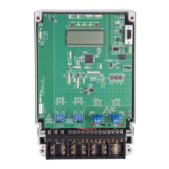
- Page 29 Figure 3-2 shows the location of various pieces of the reference design based on functionality. Figure 3-2. Top View of TIDA-010037 Design With Components Highlighted Figure 3-1. Top View of TIDA-010037 Design The design has support for two-voltage and one-voltage configurations. The hardware connections depend on which of these two configurations is selected.
- Page 30 Figure 3-4. Front View of Reference Design With Test Setup Connections, Two-Voltage Configuration High-Accuracy Split-Phase CT Electricity Meter Reference Design Using TIDUEM8B – MARCH 2019 – REVISED FEBRUARY 2021 Standalone ADCs Submit Document Feedback Copyright © 2021 Texas Instruments Incorporated...
- Page 31 Figure 3-6. Front View of Reference Design With Test Setup Connections, One-Voltage Configuration TIDUEM8B – MARCH 2019 – REVISED FEBRUARY 2021 High-Accuracy Split-Phase CT Electricity Meter Reference Design Using Submit Document Feedback Standalone ADCs Copyright © 2021 Texas Instruments Incorporated...
- Page 32 A1 as well as the ADC14 reference input. ADC of the MSP432 MCU. High-Accuracy Split-Phase CT Electricity Meter Reference Design Using Standalone ADCs TIDUEM8B – MARCH 2019 – REVISED FEBRUARY 2021 Submit Document Feedback Copyright © 2021 Texas Instruments Incorporated...
- Page 33 Pin 2 of this header is the RS-485 ground, pin 3 is the B bus I/O line, and pin 4 is the A bus I/O line. block TIDUEM8B – MARCH 2019 – REVISED FEBRUARY 2021 High-Accuracy Split-Phase CT Electricity Meter Reference Design Using Standalone ADCs Submit Document Feedback Copyright © 2021 Texas Instruments Incorporated...
- Page 34 ● Pin 6: SPI CS (ADS131M04 CS pin) ● Pin 7: RST SYNC (ADS131M04 SYNC/ RESET pin) ● GND High-Accuracy Split-Phase CT Electricity Meter Reference Design Using Standalone ADCs TIDUEM8B – MARCH 2019 – REVISED FEBRUARY 2021 Submit Document Feedback Copyright © 2021 Texas Instruments Incorporated...
- Page 35 TIDUEM8B – MARCH 2019 – REVISED FEBRUARY 2021 High-Accuracy Split-Phase CT Electricity Meter Reference Design Using Submit Document Feedback Standalone ADCs Copyright © 2021 Texas Instruments Incorporated...
- Page 36 ADS131M04 enables high accuracy even when using higher sample rates, which can be useful for applications that require harmonic analysis or load disaggregation. High-Accuracy Split-Phase CT Electricity Meter Reference Design Using TIDUEM8B – MARCH 2019 – REVISED FEBRUARY 2021 Standalone ADCs Submit Document Feedback Copyright © 2021 Texas Instruments Incorporated...
- Page 37 Date Year:month:day readings are displayed. This parameter is not displayed once per phase. TIDUEM8B – MARCH 2019 – REVISED FEBRUARY 2021 High-Accuracy Split-Phase CT Electricity Meter Reference Design Using Submit Document Feedback Standalone ADCs Copyright © 2021 Texas Instruments Incorporated...
- Page 38 5-V power connection is red. 3. Open the GUI folder and open calibration-config.xml in a text editor. High-Accuracy Split-Phase CT Electricity Meter Reference Design Using TIDUEM8B – MARCH 2019 – REVISED FEBRUARY 2021 Standalone ADCs Submit Document Feedback Copyright © 2021 Texas Instruments Incorporated...
- Page 39 "L" or "C" on the Power factor values to indicate an inductive or capacitive load, respectively. TIDUEM8B – MARCH 2019 – REVISED FEBRUARY 2021 High-Accuracy Split-Phase CT Electricity Meter Reference Design Using Submit Document Feedback Standalone ADCs Copyright © 2021 Texas Instruments Incorporated...
- Page 40 Meter calibration factors button, or open the window used for calibrating the system by clicking the Manual cal. button. High-Accuracy Split-Phase CT Electricity Meter Reference Design Using TIDUEM8B – MARCH 2019 – REVISED FEBRUARY 2021 Standalone ADCs Submit Document Feedback Copyright © 2021 Texas Instruments Incorporated...
- Page 41 3. Click on the Manual cal. button that Figure 3-12 shows. The following screen pops up from Figure 3-14: TIDUEM8B – MARCH 2019 – REVISED FEBRUARY 2021 High-Accuracy Split-Phase CT Electricity Meter Reference Design Using Submit Document Feedback Standalone ADCs Copyright © 2021 Texas Instruments Incorporated...
- Page 42 5. Enter the error obtained in Step 4 into the Active Power field under the corresponding phase in the GUI window. This error is already the value and does not require calculation. High-Accuracy Split-Phase CT Electricity Meter Reference Design Using TIDUEM8B – MARCH 2019 – REVISED FEBRUARY 2021 Standalone ADCs Submit Document Feedback Copyright © 2021 Texas Instruments Incorporated...
- Page 43 ADC is also twice as much when measuring line-to-line voltage compared to TIDUEM8B – MARCH 2019 – REVISED FEBRUARY 2021 High-Accuracy Split-Phase CT Electricity Meter Reference Design Using Submit Document Feedback Standalone ADCs Copyright © 2021 Texas Instruments Incorporated...
- Page 44 Figure 3-15. Calibration Factors Window High-Accuracy Split-Phase CT Electricity Meter Reference Design Using TIDUEM8B – MARCH 2019 – REVISED FEBRUARY 2021 Standalone ADCs Submit Document Feedback Copyright © 2021 Texas Instruments Incorporated...
- Page 45 In addition, the overcurrent threshold value that was measured to cause a thermal shutdown was 1.62 A. TIDUEM8B – MARCH 2019 – REVISED FEBRUARY 2021 High-Accuracy Split-Phase CT Electricity Meter Reference Design Using Submit Document Feedback Standalone ADCs Copyright © 2021 Texas Instruments Incorporated...
- Page 46 0.058 80.00 0.004 –0.064 0.074 90.00 0.01 –0.065 0.0845 100.00 0.014 –0.07 0.101 High-Accuracy Split-Phase CT Electricity Meter Reference Design Using TIDUEM8B – MARCH 2019 – REVISED FEBRUARY 2021 Standalone ADCs Submit Document Feedback Copyright © 2021 Texas Instruments Incorporated...
- Page 47 D001 Figure 3-17. Phase A Active Energy % Error Versus Current, Two-Voltage Mode TIDUEM8B – MARCH 2019 – REVISED FEBRUARY 2021 High-Accuracy Split-Phase CT Electricity Meter Reference Design Using Submit Document Feedback Standalone ADCs Copyright © 2021 Texas Instruments Incorporated...
- Page 48 D002 Figure 3-18. Phase B Active Energy % Error Versus Current, Two-Voltage Mode High-Accuracy Split-Phase CT Electricity Meter Reference Design Using TIDUEM8B – MARCH 2019 – REVISED FEBRUARY 2021 Standalone ADCs Submit Document Feedback Copyright © 2021 Texas Instruments Incorporated...
- Page 49 D003 Figure 3-19. Cumulative Phase Active Energy % Error Versus Current, Two-Voltage Mode TIDUEM8B – MARCH 2019 – REVISED FEBRUARY 2021 High-Accuracy Split-Phase CT Electricity Meter Reference Design Using Submit Document Feedback Standalone ADCs Copyright © 2021 Texas Instruments Incorporated...
- Page 50 D004 Figure 3-20. Cumulative Phase Active Energy % Error Versus Current, One-Voltage Mode High-Accuracy Split-Phase CT Electricity Meter Reference Design Using TIDUEM8B – MARCH 2019 – REVISED FEBRUARY 2021 Standalone ADCs Submit Document Feedback Copyright © 2021 Texas Instruments Incorporated...
- Page 51 –0.0033 10 A, 60 0.025 0.0073 0.008 10 A, 300 –0.0105 –0.009 –0.013 TIDUEM8B – MARCH 2019 – REVISED FEBRUARY 2021 High-Accuracy Split-Phase CT Electricity Meter Reference Design Using Submit Document Feedback Standalone ADCs Copyright © 2021 Texas Instruments Incorporated...
- Page 52 Current (A) D006 Figure 3-22. Phase A RMS Current % Error, Two-Voltage Mode High-Accuracy Split-Phase CT Electricity Meter Reference Design Using TIDUEM8B – MARCH 2019 – REVISED FEBRUARY 2021 Standalone ADCs Submit Document Feedback Copyright © 2021 Texas Instruments Incorporated...
- Page 53 Current (A) D007 Figure 3-23. Phase B RMS Current % Error, Two-Voltage Mode TIDUEM8B – MARCH 2019 – REVISED FEBRUARY 2021 High-Accuracy Split-Phase CT Electricity Meter Reference Design Using Submit Document Feedback Standalone ADCs Copyright © 2021 Texas Instruments Incorporated...
- Page 54 Voltage (V) D008 Figure 3-24. Phase A RMS Voltage % Error, Two-Voltage Mode High-Accuracy Split-Phase CT Electricity Meter Reference Design Using TIDUEM8B – MARCH 2019 – REVISED FEBRUARY 2021 Standalone ADCs Submit Document Feedback Copyright © 2021 Texas Instruments Incorporated...
- Page 55 Voltage (V) D009 Figure 3-25. Phase B RMS Voltage % Error, Two-Voltage Mode TIDUEM8B – MARCH 2019 – REVISED FEBRUARY 2021 High-Accuracy Split-Phase CT Electricity Meter Reference Design Using Submit Document Feedback Standalone ADCs Copyright © 2021 Texas Instruments Incorporated...
- Page 56 Current (A) D001 Figure 3-26. Active Energy % Error Versus Current, 32 ksps High-Accuracy Split-Phase CT Electricity Meter Reference Design Using TIDUEM8B – MARCH 2019 – REVISED FEBRUARY 2021 Standalone ADCs Submit Document Feedback Copyright © 2021 Texas Instruments Incorporated...
-
Page 57: Pcb Layout Recommendations
To download the schematics, see the design files at TIDA-010037. 4.2 Bill of Materials To download the bill of materials (BOM), see the design files at TIDA-010037. 4.3 PCB Layout Recommendations For this design, the following general guidelines must be followed: •... -
Page 58: Related Documentation
All trademarks are the property of their respective owners. 6 About the Author MEKRE MESGANAW is a systems engineer in the Grid Infrastructure group at Texas Instruments, where he primarily works on grid monitoring reference design development. Mekre received his bachelor of science and master of science in computer engineering from the Georgia Institute of Technology. - Page 59 TI products. TI’s provision of these resources does not expand or otherwise alter TI’s applicable warranties or warranty disclaimers for TI products.IMPORTANT NOTICE Mailing Address: Texas Instruments, Post Office Box 655303, Dallas, Texas 75265 Copyright © 2021, Texas Instruments Incorporated...
Need help?
Do you have a question about the TIDA-010037 and is the answer not in the manual?
Questions and answers