Table of Contents
Advertisement
Quick Links
____________________________________________________________________________________________________________________________________________________________________________________
_________________________________________________________________________________________________________________________________________________________________________________
Rotary lift Consolidated (Haimen) Co., Ltd
Address:No.1388 Xiushan East Road,
Haimen Economic Development
Zone, Jiangsu Province,china,226100
SGL35ME001-EU
SGL35MF001-EU
2-Post Vehicle Lift
SGL35M
User Manual
Tel:(086-0513) 82221748,82100577
Hotline: (086)800-828-3302
Fax:(086-0513)82109505
Website: http://www.rotaryliftasia.com
Rev.C 2021.07
Advertisement
Table of Contents

Related Manuals for Rotary SGL35M


Summary of Contents for Rotary SGL35M
- Page 1 2-Post Vehicle Lift SGL35M User Manual ____________________________________________________________________________________________________________________________________________________________________________________ _________________________________________________________________________________________________________________________________________________________________________________ Rotary lift Consolidated (Haimen) Co., Ltd Tel:(086-0513) 82221748,82100577 Address:No.1388 Xiushan East Road, Hotline: (086)800-828-3302 Haimen Economic Development Fax:(086-0513)82109505 Zone, Jiangsu Province,china,226100 Website: http://www.rotaryliftasia.com Rev.C 2021.07 SGL35ME001-EU SGL35MF001-EU...
-
Page 3: Table Of Contents
1. Introduction 6.4 Recommissioning the lift after incorrect Contents alignment of the slider blocks ....18 Maintenance ..........19 Introduction ..........2 7.1 Maintenance staff qualification .... 19 1.1 About this operating manual ....2 7.2 Safety regulations ........ 19 1.2 Important information for the machine 7.3 Maintenance schedule ...... -
Page 4: Introduction
1. Introduction 1.2 Important information for the Introduction machine operator The operating manual contains important information for safe operation and for the functional 1.1 About this operating manual reliability of the lift. The post lift conforms to state of the art technology ... -
Page 5: Specialist For Safety Related Work
1. Introduction people. Non-compliance may lead to 1.3 Specialist for safety related death or serious injury. work Risk of death or injury The post lift must be inspected after commissioning Potential risk to life and health of and at regular intervals but at least annually. people. -
Page 6: Intended Use
2. Intended use The manufacturer assumes no liability for Intended use damage of any kind which arises through incorrect, erroneous, or unreasonable use. 2.1 General The lift Risk of injury! 3.1 Functionality WARNING The lift is designed to raise vehicles to the ... -
Page 7: System Overview
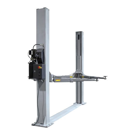
3. The lift 3.2 System overview Figure 1: Example of a post lift Adapter Primary column Slide Secondary column 10 Base plate support (optional extra) Drive-through ramp 11 Lever for latch mechanism Control unit 12 Latch mechanism cover Hydraulic unit 13 Hole for anchor bolts Column base plate 14 Cover plate... -
Page 8: Technical Data
3. The lift 3.3 Technical data 3.4 Identification of lift The customer service department of your authorised SGL35M dealer can react quicker to your maintenance queries if you specify the lift, serial number, and any Load capacity / Lift cylinder [kg] 3500 possible accessories. -
Page 9: Permitted Weight Distribution
3. The lift Permitted weight distribution Figure 3: Vehicle centre of gravity The weight distribution on the adapters is reversible for this post lift: The heavy load can either be placed on the long or the short arms P1 (1/3) - P2 (2/3) of the maximum load. Figure 3: Minimum distance between two adapters ... -
Page 10: Safety Mechanisms
3. The lift 3.6 Safety mechanisms Figures 5 ... 9: Safety mechanisms Electrical Emergency stop button on the control unit (Figure 5) Broken chain and slack chain switch (lifting chain): consists of a micro switch, which is fitted in each column at the bottom. -
Page 11: Control Box
3. The lift 3.7 Control box (see figure 11) Main switch, emergency stop To connect the lift to the mains supply, turn the switch to ”1", to disconnect from the power supply turn it to ”0". Control box key Opens the control box for maintenance purposes. -
Page 12: Safety Regulations
4. Safety regulations During the raising and lowering process, no-one Safety regulations ● should loiter within range of the moving load and the pick-up points. Comply with the following regulations! Briefly raise the lift to check that the vehicle ● pick-up points are secure. -
Page 13: Operation
5. Operation Operation 5.4 Driving the vehicle onto the Risk of injury if an incorrect lift procedure is followed during Unauthorised or untrained persons may NOT breakdowns. DANGER operate the lift and may NOT lift the vehicle. If there are indications of faults such as ... -
Page 14: Using The Lift
5. Operation The vehicle must now be lowered by an lever and push the DOWN button to lower the authorised competent person. lift to the required level. 2. If you cannot pull the lever down, the latching ONLY use adapter extensions from the lift manufacturer. -
Page 15: Switch Off The System
5. Operation 3. Drive the vehicle away from the lift. 5.9 Switch off the system 1. Set the main switch to “0". -
Page 16: Action In The Event Of A Fault
6. Action in the event of a fault Action in the event of a 6. Broken chain switch or the lifting chain has reacted to unusual tensioning of the lifting chain. fault Remedy: 1. Connect the control unit to the power supply. ... - Page 17 6. Action in the event of a fault manually disengage the latches, hold them in this Cause: position with wedges, lower the lift, then remove the 1. Fuse or circuit breaker burnt out. wedges. Correct the cable tension or replace the 2.
- Page 18 6. Action in the event of a fault 3. Repair the external leak. 3. The cable is loose. Remedy: The lift rises unevenly. 1. Replace the cable. 2. Check and repair the Bowden cable and its Cause: mounting. 1. The synchronisation cables are offset. 3.
-
Page 19: Emergency Lowering
6. Action in the event of a fault Careful use by authorised and qualified 6.3 Emergency lowering operators Only competent persons may carry out The area around the lift must be made safe in emergency lowering of the vehicle. compliance with national regulations ... -
Page 20: Recommissioning The Lift After Incorrect Alignment Of The Slider Blocks
6. Action in the event of a fault Latch Cable clamp Short cable clamp Mounting plate Secondary column Latch Primary Cable clamp column Anchor Long cable clamp A synchronisation cable has become slack for no obvious reason: press the "Up” button, to 6.4 Recommissioning the lift tension the cable again (Fig. -
Page 21: Maintenance
7. Maintenance Lifts in especially dirty environments must be Maintenance cleaned and maintained more often. Oil and grease are water pollutants. Always dispose of them in an environmentally friendly 7.1 Maintenance staff manner according to the regulations qualification applicable in your country ( Chapter 14, Disposal). -
Page 22: Cleaning
7. Maintenance 7.4 Cleaning Approved hydraulic oils Keep the lift and the lifting zone spotlessly Important advice clean. Never use compressed air, water jets, Only use hydraulic oil according to DIN 51524 solvents, or abrasive cleaning materials to clean for hydraulic systems. -
Page 23: Carry Out A Function Test
8. Repairs Hold the cables just under the slider block Repair work may only be carried out on between your thumb and forefinger and press equipment that is switched off and locked by together with approx. 70 N of force. trained and authorised specialists. -
Page 24: Unpacking
10. Transport, storage Do not loiter close to or under suspended loads. Always unload the packing unit with a forklift truck or a pallet jack with sufficient load capacity and transport it to the storage point. Always use hoisting equipment (straps, chains, etc.) approved for the total weight. -
Page 25: Installation
11. Installation Installation Lift 11.1 Installation guidelines SGL35M 13.2 Refer to the health & safety M = Tilt movement specified in kNm on the requirements when choosing an column base plate installation site CAUTION F = Force specified in kN Shut down and secure the lift immediately if function failures occur. -
Page 26: Mechanical Installation
11. Installation ・ Now run in the synchronisation cables and the latch cable before aligning the columns 11.2 Mechanical installation according to the diagram in Fig. 22. a) Preparation before b) Assembling the columns installing the columns ・ ・ Use a piece of wood (from the packaging) to Identify the columns with the help of the latches on the mechanical safety system: The primary support the slider block 10 cm above the base... - Page 27 11. Installation Cable clamp Latch Short cable clamp Mounting plate Secondary column Cable clamp Latch Primary column Anchor Long cable clamp Drill diameter 3/4" inch Set up the columns vertically or slightly tilted Recommended concrete outwards with the help of a plumb line. If the 200 mm thickness floor is not level, use the supplied shims under...
-
Page 28: Hydraulic Installation
11. Installation Drill holes with a 3/4" inch Clean out the hole masonry drill with a Tighten the nut until it Tighten the nut to carbide bit engages, Turn the anchor in 200 Nm with an the hole until the nut and the adjustable wrench lock washer touch the base plate... -
Page 29: Final Assembly Of The Mechanical Unit
11. Installation Disconnect the cable from the 400 V terminal on the transformer and connect it to the 230 V 11.5 Final assembly of the terminal. mechanical unit Remove the cover of the motor terminal box. Loosen the M5 lock nuts on the terminal strip and change its position (Fig. - Page 30 11. Installation For part No.105 , this side fit into cylinder • c) Assembling the latch cable Adjust the tension of the cable with the clamp so that both latches disengage from their rack at To make this step easier, raise the slider the same time when you pull the latch block to the top position.
- Page 31 11. Installation Note: Pay attention to the When assembling the bolt orientation of the bevelled gear! CAUTION Pinch point To test the function of the arms after assembly, raise the slider block at least 25 mm from the bottom position. Pull up the bolt ring and bring the arms into the desired position.
-
Page 32: Commissioning
12. Commissioning Ensure that the hydraulic system fittings are 12. Commissioning properly sealed. Check the hydraulic oil level in the tank when Carry out a “safety inspection“ before the slider block is in the bottom position. commissioning. Check that the hydraulic lines are correctly If a competent person (factory-trained fitter) installs positioned and that they do not chafe against... - Page 33 12. Commissioning Each of the chains is fitted with a micro switch pulled tight and brings the slider block on the control (Fig. 30), which monitors the chain tension. If side to a halt (cable is loaded). the chain breaks or is excessively slack the ...
-
Page 34: Disassembly
13. Disassembly Special waste must be separated and subdivided Disassembly into equal lots and then disposed of in accordance with national legislation and Disassembly work may only be carried out by standards. authorised specialist staff. Electrical work may only be carried out by qualified electricians. -
Page 35: Annex
Annex Post Lift SGL35M ANNEX Notes on conducting a visual in spection and a function test Diagrams, spare parts lists ・ Electrical circuit diagram → see control box ・ ・ Hydraulic diagram Spare parts lists... - Page 36 Annex Post Lift SGL35M Notes on conducting the visual inspection and function tests Check the following in particular in the course of a regular inspection: 1. Information on the lift Inspection criteria Nameplate Securely fastened Labelling Legibility Brief operating instructions Complete 2.
- Page 37 Annex Post Lift SGL35M 10. Pick-up equipment Anti-slip protection Condition Roll stop Function Clamping equipment Arm restraints 11. Steel cables / steel links Wear Corrosion Torn strands Torn strand nests Crushing Outer layer fraying Bird caging 12. Sheaves Cracking Signs of wear...
- Page 38 Annex Post Lift SGL35M Dirt t l i condition Pressure release valve Surface condition Seals undamaged Lowering valve Surface condition, seals 15. Electrical equipment Wires Damage, strength, strain relief on outer wires Grounding conductor Damage, strength 16.Safety latches Effectiveness, strength, condition, damage 17.
- Page 39 Diagrams, spare parts lists Electrical Circuit Diagram(single phase)...
- Page 40 Diagrams, spare parts lists Electrical Circuit Diagram(3 phase)...
- Page 41 Diagrams, spare parts lists Hydraulic System of SGL35M a,Hydraulic principle diagram b, Hydraulic components list Descend throttle Oil cylinder solenoid valve One way valve Oil return throttle Oil pump Overflow valve Oil drum Volume 10 liter Oil filter Optional Motor 3-phase 380V,50Hz,2.2Kw No. Description Model Specifications QTY. Remark...
- Page 42 When pressing the rise button on control box, the motor starts up to drive the oil pump and suck pressure oil from the oil pump to oil cylinder No.A9 to drive piston rod. At this point the overflow valve No.A4 closes and pressure has been adjusted in factory. Ensure the nominal lifting load meet the requirements.However, when systematic pressure exceeds limits, the overflow valve starts to discharge oil automatically. Release lift button to stop oil supply and when lifting movement stops the operation begins. If it is intended to descend, pull unlock lever and press descend button, A8 electromagnetic valve opens to discharge oil....
- Page 43 Diagrams, spare parts lists Spare parts list Item Drawing no. Name Item Drawing no. Name SGL35-1000M Welded primary column SGL35-6003 Cable duct SGL35-1100M Welded secondary column SGL35-6002 Synchronisation cable SGL35-6004 Cover plate N619 Cable mounting SGL35-1020 C-base plate G3T-5001 Arm bolt SGL35-3000 Welded base plate 40155...
- Page 44 Diagrams, spare parts lists...
- Page 45 Figure 2...
- Page 46 Diagrams, spare parts lists Figure 3 Figure 4...
- Page 47 Figure 5 Figure 6 Figure 7...
- Page 48 Diagrams, spare parts lists Figure 8...
- Page 49 Figure 9...
- Page 50 Diagrams, spare parts lists...
- Page 51 Rotary Lift Consolidated (Haimen) Co., Ltd Tel: (0513) 82221748, 82100577 Address: No. 1388 Xiushan East Road, Fax:(0513)82109505 Haimen Economic Development Zone, Jiangsu Province Hotline: 800-828-3302 Postal Code: 226100 Website: http://www.rotaryliftasia.com...
Need help?
Do you have a question about the SGL35M and is the answer not in the manual?
Questions and answers