Tecnam P2008 JC Aircraft Flight Manual
Hide thumbs
Also See for P2008 JC:
- Flight manual (265 pages) ,
- Aircraft flight manual (202 pages) ,
- Flight manual (196 pages)
Table of Contents
Advertisement
Quick Links
Updated AFM incorporating Supplements for G-JACM
Based on Dec No 2008/100 Ed 2 - Rev 1 2018, March 12th
FOR REFERENCE ONLY - ORIG AFM IS DEFINITIVE
M
:
ANUFACTURER
A
:
IRCRAFT MODEL
EASA T
C
YPE
ERTIFICATE
S
:
ERIAL NUMBER
B
:
UILD YEAR
R
EGISTRATION MARKINGS
This Aircraft Flight Manual is approved and applies only to EASA CS-VLA certified
airplanes.
This Manual must be carried in the airplane at all times.
This aeroplane has to be operated in compliance with procedures and limitations contained
herein.
Costruzioni Aeronautiche TECNAM srl
Via Maiorise
CAPUA (CE) – Italy
Tel. +39-0823 997538
WEB:
www.tecnam.com
Aircraft Flight Manual
Doc. No. 2008/100
Ed. 2 – Rev. 2
2018, August 02
TECNAM P2008 JC
C. A. TECNAM S.r.l.
P2008 JC
N
.:
R
A .583 (
DATED
1112
...............................
2018
...............................
G-JACN
:
...............................
th
2013, 27 S
)
EPTEMBER
Updated AFM incorporating Supplements
Based on Dec No 2008/100
Ed 2 - Rev 1 2018, March 12th
FOR REFERENCE ONLY
ORIGINAL AFM IS DEFINITIVE
Page 0 - 1
Advertisement
Table of Contents

Related Manuals for Tecnam P2008 JC


Summary of Contents for Tecnam P2008 JC
- Page 1 2018, August 02 Updated AFM incorporating Supplements for G-JACM Based on Dec No 2008/100 Ed 2 - Rev 1 2018, March 12th FOR REFERENCE ONLY - ORIG AFM IS DEFINITIVE TECNAM P2008 JC ANUFACTURER C. A. TECNAM S.r.l. IRCRAFT MODEL...
- Page 2 Page 0 - 2 SECTION 0 INDEX 1. RECORD OF REVISIONS ..................3 2. LIST OF EFFECTIVE PAGES ..................7 3. FOREWORD ......................9 4. SECTIONS LIST ......................10 Ed. 2, Rev. 0 Aircraft Flight Manual INDEX...
-
Page 3: Record Of Revisions
Page 0 - 3 1. RECORD OF REVISIONS Any revision to the present Manual, except actual weighing data, is recorded: a Record of Revisions is provided in this Section and the operator is advised to make sure that the record is kept up-to-date. The Manual issue is identified by Edition and Revision codes reported on each page, lower right side. - Page 4 Page 0 - 4 EASA Approval or Tecnam Approval Under DOA Revised Description of Privileges page Revision Approved under the authority of DOA, Editorial revision. A. Sabino C. Caruso M. Oliva ref. EASA.21J.335 (MOD2008/097.180126) 0-1,4,7 Cover, RoR and LOEP updated.
- Page 5 Page 0 - 5 INTENTIONALLY LEFT BLANK Ed. 2, Rev. 0 Aircraft Flight Manual...
- Page 6 Page 0 - 6 INTENTIONALLY LEFT BLANK Ed. 2, Rev. 0 Aircraft Flight Manual...
- Page 7 Page 0 - 7 2. LIST OF EFFECTIVE PAGES The List of Effective Pages (LOEP), applicable to manuals of every operator, lists all the basic AFM pages: each manual could contain either basic pages or one variant of these pages when the pages of some Supplements are embodied. Pages affected by the current revision are indicated by an asterisk (*) following the re- vision code.
- Page 8 Page 0 - 8 INTENTIONALLY LEFT BLANK Ed. 2, Rev. 0 Aircraft Flight Manual...
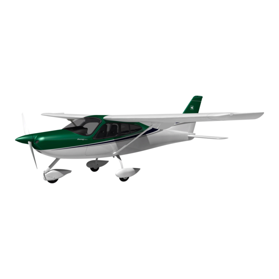
- Page 9 Page 0 - 9 3. FOREWORD Tecnam P2008 JC is a single-engine two-seat aircraft with a strut braced high wing and fixed landing gear. Section 1 provides general information and it contains definitions, symbols explana- tions, acronyms and terminology used.
-
Page 10: Sections List
Page 0 - 10 4. SECTIONS LIST General (*) Section 1 Limitations (**) Section 2 Emergency Procedures (**) Section 3 Normal Procedures (**) Section 4 Performance (***) Section 5 Weight and balance (*) Section 6 Section 7 Airframe and Systems description (*) Section 8 Ground Handling and Service (*) AFM Supplements list (*) -
Page 11: Section 1 - General
Page 1 - 1 SECTION 1 - GENERAL INDEX INTRODUCTION ....................3 CERTIFICATION BASIS ..................3 WARNINGS – CAUTIONS – NOTES ..............3 THREE-VIEW AND DIMENSIONS ................. 4 ENGINE ....................... 6 PROPELLER ......................6 FLIGHT CONTROL SURFACES TRAVEL .............. 7 SPECIFIC LOADINGS................... - Page 12 Page 1 - 2 INTENTIONALLY LEFT BLANK Ed. 2, Rev 0 Section 1 – General...
-
Page 13: Certification Basis
Page 1 - 3 1. INTRODUCTION The Flight Manual has been prepared to provide pilots and instructors with in- formation for the safe and efficient operation of this very light airplane. This manual includes the material required to be furnished to the pilot of CS- VLA. - Page 14 Page 1 - 4 4. THREE-VIEW AND DIMENSIONS Figure 1 – General views Ed. 2, Rev 0 Section 1 – General THREE-VIEW AND DIMENSIONS...
-
Page 15: General Features
Page 1 - 5 Dimensions Wing Wing Span 9.00 m (29.5 ft) Wing Area 12.16 m (130.9 ft Aspect Ratio Taper Ratio Wing chord 1.373 m (4.5 ft) Fuselage Overall length 6.93 m (22.9 ft) Overall width 1.20 m (3.9 ft) Overall height 2.67 m (8.8 ft) Empennage... - Page 16 AFMS S9 - MTV-34 Propeller for aircraft with MTOW Increment at 650 kg Page MT1-6 NGINE Manufacturer Bombardier-Rotax GmbH Model 912 S2 Engine type 4 cylinders horizontally opposed with 1352 c.c. of overall displacement, liquid cooled cylinder heads, ram-air cooled cylinders, two carburetors, integrated re- duction gear box with torsional shock ab- sorber and overload clutch.
-
Page 17: Specific Loadings
AFMS S9 - MTV-34 Propeller for aircraft with MTOW Increment at 650 kg Page MT1-7 7. FLIGHT CONTROL SURFACES TRAVEL Ailerons Up 22° Down 14 ° ( 2°) Stabilator (refer to Trailing Edge) Up 4° Down 15° ( 2°) Stabilator trim tab (refer to Trailing Edge) Up 2°;... -
Page 18: Acronyms And Terminology
Page 1 - 8 9. ACRONYMS AND TERMINOLOGY KCAS Calibrated Airspeed is the indicated airspeed expressed in knots, corrected taking into account the errors related to the instrument itself and its installation. KIAS Indicated Airspeed is the speed shown on the airspeed indicator and it is expressed in knots. - Page 19 Page 1 - 9 Meteorological terminology International Standard Atmosphere: is the air atmospheric standard condition at sea level, at 15°C (59°F) and at 1013.25hPa (29.92inHg). Official atmospheric pressure at airport level: it indicates the air- craft absolute altitude with respect to the official airport level. Theoretical atmospheric pressure at sea level: is the atmospheric pressure reported at the medium sea level, through the standard air pressure-altitude relationship, starting from the airport QFE.
- Page 20 Page 1 - 10 Aircraft performance and flight planning terminology Crosswind Velocity is the velocity of the crosswind component for the which adequate control of the air- plane during takeoff and landing is assured. Usable fuel is the fuel available for flight planning. Unusable fuel is the quantity of fuel that cannot be safely used in flight.
- Page 21 Page 1 - 11 Weight and balance terminology Datum “Reference datum” is an imaginary vertical plane from which all horizontal distances are measured for balance purposes. is the horizontal distance of an item meas- ured from the reference datum. Moment is the product of the weight of an item multiplied by its arm.
- Page 22 Page 1 - 12 INTENTIONALLY LEFT BLANK Ed. 2, Rev 0 Section 1 – General...
-
Page 23: Unit Conversion Chart
Page 1 - 13 10. UNIT CONVERSION CHART MOLTIPLYING YIELDS EMPERATURE Fahrenheit [°F] Celsius [°C] [°F] Celsius [°C] Fahrenheit ORCES Kilograms [kg] 2.205 Pounds [lbs] Pounds [lbs] 0.4536 Kilograms [kg] PEED Meters per second [m/s] 196.86 Feet per minute [ft/min] Feet per minute [ft/min]... - Page 24 Page 1 - 14 11. LITRES / US GALLONS CONVERSION CHART Litres US Gallons US Gallons Litres 11.4 15.1 22.7 30.3 37.9 10.6 45.4 11.9 53.0 13.2 60.6 15.9 68.1 18.5 75.7 21.1 83.3 23.8 90.9 26.4 98.4 29.1 106.0 31.7 113.6 34.3...
- Page 25 Page 2 - 1 SECTION 2 – LIMITATIONS INDEX INTRODUCTION ..................3 AIRSPEED LIMITATIONS ................5 AIRSPEED INDICATOR MARKINGS ............6 POWERPLANT LIMITATIONS ..............7 FUEL ......................8 LUBRICANT ....................8 COOLANT LIQUID ..................8 PAINT ....................... 8 PROPELLER ....................9 10.
- Page 26 Page 2 - 2 INTENTIONALLY LEFT BLANK Ed. 2, Rev. 0 Section 2 – Limitations...
- Page 27 Page 2 - 3 1. INTRODUCTION Section 2 includes operating limitations, instrument markings, and basic placards necessary for safe operation of the aeroplane, its engine, standard systems and standard equipment. Ed. 2, Rev. 0 Section 2 – Limitations INTRODUCTION...
- Page 28 Page 2 - 4 INTENTIONALLY LEFT BLANK Ed. 2, Rev. 0 Section 2 – Limitations...
-
Page 29: Airspeed Limitations
AFMS S9 - MTV-34 Propeller for aircraft with MTOW Increment at 650 kg Page MT2-5 2. AIRSPEED LIMITATIONS The following table addresses the airspeed limitations and their operational signif- icance: AIRSPEED KIAS KCAS REMARKS Never exceed speed Do not exceed this speed in V NE any operation. -
Page 30: Airspeed Indicator Markings
AFMS S9 - MTV-34 Propeller for aircraft with MTOW Increment at 650 kg Page MT2-6 3. AIRSPEED INDICATOR MARKINGS Airspeed indicator markings and their colour code are explained in the following table. MARKING KIAS EXPLANATION White arc/band 40 – 70 Positive Flap Operating Range (lower limit is V , at specified maximum weight and... -
Page 31: Powerplant Limitations
Page 2 - 7 4. POWERPLANT LIMITATIONS Following table reports the powerplant operating limitations: : Bombardier Rotax GmbH. NGINE MANUFACTURER : 912 S2 NGINE MODEL AXIMUM POWER Max Power Max rpm. Time max. kW (hp) Prop. rpm(engine) (minutes) Max. T.O. 73.5 (98.6) 2388 (5800) Max. - Page 32 Page 2 - 8 5. FUEL 62 litres each one (16.38 US gallons) ANKS 124 litres (32.76 US gallons) AXIMUM CAPACITY 120 litres (32 US gallons) AXIMUM USABLE FUEL MOGAS ASTM D4814 (min RON 95/AKI 91) PPROVED FUEL MOGAS EN 228 Super/Super plus (min. RON 95/AKI 91) AVGAS 100 LL (ASTM D910) Prolonged use of Aviation Fuel Avgas 100LL results in greater wear of valve seats and greater combustion deposits...
-
Page 33: Maximum Operating Altitude
AFMS S9 - MTV-34 Propeller for aircraft with MTOW Increment at 650 kg Page MT2-9 9. PROPELLER Manufacturer MT Propeller Model MTV-34-1-A/170-202 Number of blades Construction Laminated hard wood with epoxy fibre glass cover Diameter 1700 mm Type Fixed pitch 10. - Page 34 Page 2 - 10 12. POWERPLANT INSTRUMENTS MARKINGS Powerplant instrument markings and their colour code significance are shown be- low: RED LINE GREEN ARC YELLOW ARC RED LINE Minimum Normal Caution Maximum NSTRUMENT limit operating limit Propeller ---- 577 - 2265 2265 - 2388 2388 Oil temp.
- Page 35 Page 2 - 11 INTENTIONALLY LEFT BLANK Ed. 2, Rev. 0 Approved Section 2 – Limitations...
- Page 36 AFMS S9 - MTV-34 Propeller for aircraft with MTOW Increment at 650 kg Page MT2-12 14. WEIGHTS Condition Weight Maximum takeoff weight 650 kg 1433lb Maximum landing weight 650 kg 1433lb Baggage Compartment Maximum weight 20 kg 44lb Maximum specific pressure 12,5 kg/dm 256 lbs/sq in Ed 2, Rev.
- Page 37 Page 2 - 13 INTENTIONALLY LEFT BLANK Ed. 2, Rev. 0 Approved Section 2 – Limitations...
-
Page 38: Center Of Gravity Range
Page 2 - 14 15. CENTER OF GRAVITY RANGE Datum Vertical plane tangent to the propeller flange (the aircraft must be levelled in the longitudinal plane) Levelling Refer to the seat track supporting beams (see procedure in Section 6) Forward limit 1.841 m (20% MAC) aft of datum for all weights Aft limit 1.978 m (30% MAC) aft of datum for all weights... - Page 39 Page 2 - 15 INTENTIONALLY LEFT BLANK Ed. 2, Rev. 0 Approved Section 2 – Limitations...
-
Page 40: Approved Manoeuvres
AFMS S9 - MTV-34 Propeller for aircraft with MTOW Increment at 650 kg Page MT2-16 16. APPROVED MANOEUVRES The aircraft is certified in Normal Category in accordance with EASA CS-VLA regu- lation applying to aeroplanes intended for non-aerobatic operation only. Non aerobatic operation includes: Any manoeuvre pertaining to “normal”... - Page 41 AFMS S9 - MTV-34 Propeller for aircraft with MTOW Increment at 650 kg Page MT2-17 17. MANOEUVRES LOAD FACTOR LIMITS Manoeuvre load factors limits are as follows: Positive Negative + 3.8 g - 1.9 g Manoeuvre load factors limits with flaps extended are as follows: Positive Negative + 1.9 g...
-
Page 42: Demonstrated Cross Wind Safe Operations
Page 2 - 18 18. DEMONSTRATED CROSS WIND SAFE OPERATIONS The aircraft controllability, during take-offs and landings, has been demonstrated with a cross wind components of 15kts. 19. FLIGHT CREW Minimum crew: 1 pilot Maximum number of occupants: 2 people (including the pilot) Ed. - Page 43 AFMS S8 - MD302 and G3X Touch Page M2-19 20. KINDS OF OPERATION EQUIPMENT LIST (KOEL) This paragraph reports the KOEL table, concerning the equipment list required on board under CS-VLA regulations to allow flight operations in VFR Day and VFR Night.
- Page 44 AFMS S8 - MD302 and G3X Touch Page M2-20 Equipment VFR Day VFR Night MD302 (PFI) ● ● MAGNETIC DIRECTION INDICATOR ● ● ANALOGUE FUEL QUANTITY INDICATORS ● ● ANALOGUE CT (or CHT if applicable) ● ● INDICATOR ANALOGUE RPM INDICATOR ●...
-
Page 45: Limitations Placards
AFMS S9 - MTV-34 Propeller for aircraft with MTOW Increment at 650 kg Page MTN2-21 21. LIMITATIONS PLACARDS The following limitation placards are placed in plain view on the pilot, reminding the observance of aircraft operating limitations according to installed equipment configuration (see KOEL, Para. - Page 46 AFMS S8 - MD302 and G3X Touch Page M2-22 Below the G3X Touch LH screen, the following label is placed: Ed. 2, Rev. 0 Approved Section 2 – Limitations LIMITATIONS PLACARDS...
-
Page 47: Other Placards
Page 2 - 23 22. OTHER PLACARDS Engine compartment placards Oil brakes reservoir placard Ed. 2, Rev. 0 Approved Section 2 – Limitations OTHER placards... - Page 48 Page 2 - 24 Usable fuel markings Allowed fuel placard Emergency exit placard Parking brake placard Ed. 2, Rev. 0 Approved Section 2 – Limitations OTHER placards...
- Page 49 AFMS for VFR NIGHT equipped airplanes Page 2N - 25 Throttle marking Fuel selector valve marking Choke placard Alternate static port placard Ed. 2, Rev. 0 Approved Section 2 – Limitations OTHER PLACARDS...
- Page 50 AFMS for VFR NIGHT equipped airplanes Page 2N - 26 Cabin heat/defrost placard Carb heat placard Ignition key placard Master/Generator placards Map-light placard Ed. 2, Rev. 0 Approved Section 2 – Limitations OTHER PLACARDS...
- Page 51 Page 2 - 27 Flap indicator placard Backrest lever placard Safety equipment location placard Elt placard Battery placard Ed. 2, Rev. 0 Approved Section 2 – Limitations OTHER placards...
- Page 52 AFMS S8 - MD302 and G3X Touch Page M2-28 Upper panel Switches labels Door lock lever Ed. 2, Rev. 0 Approved Section 2 – Limitations OTHER PLACARDS...
- Page 53 Page 2 - 29 INTENTIONALLY LEFT BLANK Ed. 2, Rev. 0 Approved Section 2 – Limitations OTHER placards...
- Page 54 Page 2 - 30 INTENTIONALLY LEFT BLANK Ed. 2, Rev. 0 Approved Section 2 – Limitations OTHER placards...
- Page 55 AFMS for VFR NIGHT equipped airplanes Page 3N - 1 SECTION 3 – EMERGENCY PROCEDURES INDEX 1. INTRODUCTION ................3 2. AIRPLANE ALERTS ................. 4 2.1. Electric Power System Malfunction ............... 5 2.2. G3X Failures ....................6 2.3. Pitot Heating System Failure ................7 3.
- Page 56 Page 3 - 2 INTENTIONALLY LEFT BLANK Ed. 2, Rev. 0 Section 3 – Emergency procedures INDEX...
- Page 57 Page 3 - 3 1. INTRODUCTION Section 3 includes checklists and detailed procedures to be used in the event of emergencies. Emergencies caused by a malfunction of the aircraft or engine are extremely rare if appropriate maintenance and pre-flight inspections are carried out.
- Page 58 Page 3 - 4 2. AIRPLANE ALERTS The alert lights, located on the instrument panel can have the following colours: GREEN to indicate that pertinent device is turned ON AMBER to indicate no-hazard situations that have to be considered and which require a proper crew action to indicate emergency conditions Ed.
-
Page 59: Electric Power System Malfunction
AFMS for VFR NIGHT equipped airplanes Page 3N - 5 2.1. E LECTRIC OWER YSTEM ALFUNCTION Alternator Failure Light ON Alternator light may illuminate for a faulty alternator or when voltage is above 16V; in this case the over-voltage sensor auto- NOTE matically shuts down the alternator. - Page 60 AFMS S8 - MD302 and G3X Touch Page M3-6 2.2. G3X T OUCH AILURES In case of LH or RH display failure, navigation and engine data will be automati- cally available in the remaining display (split mode). INSTRUCTION: revert to the remaining display. Garmin G3X is NOT intended to be used as primary reference for flight and navigation information but only provides information for increased situational awareness.
- Page 61 AFMS for VFR NIGHT equipped airplanes Page 3N - 7 ITOT EATING YSTEM AILURE When the Pitot Heat system is activated, the green PITOT HEAT ON safe operating annunciation is ON; If the amber PITOT HEAT is turned ON, but the caution remains ON, the Pitot Heat system is not functioning properly.
- Page 62 Page 3 - 8 3. AIRPLANE EVACUATION With the engine secured and propeller stopped (if practical): Parking brake: Seat belts: unstrap completely Headphones: REMOVE Door: OPEN Escape away from flames/ hot engine compartment/ spilling fuel tanks/ Hot brakes. ENGINE SECURING Following procedure is applicable to shut-down the engine in flight: Throttle Lever IDLE...
-
Page 63: After Take - Off
AFMS S9 - MTV-34 Propeller for airplanes with MTOW Increment at 650 kg Page MT3 - 9 5. ENGINE FAILURE 5.1. NGINE AILURE URING Throttle: IDLE (keep fully out) Rudder: Keep heading control Brakes: apply as needed when safely stopped: OFF. - Page 64 AFMS for VFR NIGHT equipped airplanes Page 3N - 10 NGINE AILURES URING LIGHT 5.3.1 Low Fuel Pressure If the fuel pressure indicator falls below 2.2 psi / FP LOW warning is ON: Electric fuel pump: Fuel selector valve: select opposite fuel tank if NOT empty Check both Fuel quantity indicators: If fuel pressure does not build up:...
- Page 65 AFMS for VFR NIGHT equipped airplanes Page 3N - 11 5.3.2 Low Oil Pressure If oil pressure is below12 psi / OP LOW warning is ON: Throttle Lever REDUCE to Minimum practical Land as soon as practical If oil pressure does not increase and OP LOW warning persists ON: Land as soon as possible applying forced landing procedure (See Para.
- Page 66 Page 3 - 12 5.3.3 High Oil Temperature If OP LOW warning is ON, see para. 5.3.2 “Low Oil Pressure”. If oil pressure is within limits: Throttle Lever REDUCE to Minimum practical If oil temperature does not decrease Airspeed INCREASE if practical If oil temperature does not come back within limits, the thermostatic valve regulating the oil flow to the heat NOTE...
- Page 67 Page 3 - 13 5.3.4 CHT/CT limit exceedance If CHT is above 135°C or CT is above 120°C, apply following procedure: If OP LOW warning is ON, see para. 5.3.2 “Low Oil Pressure”. If oil pressure is within limits: Throttle Lever REDUCE Minimum practical Land as soon as practical If CHT/CT does not come back within limits, the ther-...
-
Page 68: In-Flight Engine Restart
Page 3 - 14 6. IN-FLIGHT ENGINE RESTART After a mechanical engine seizure, fire or a major propeller damage engine restart is not recommended. WARNING Carburettor heat ON if required Electrical fuel pump Fuel quantity indicator CHECK select opposite tank if not empty Fuel Selector Ignition key BOTH... -
Page 69: Smoke And Fire
Page 3 - 15 7. SMOKE AND FIRE 7.1. NGINE FIRE ON THE GROUND Fuel Selector Electrical fuel pump Ignition key Throttle lever FULL POWER Cabin Heat Alternator & Master Switches Parking Brake ENGAGED Aircraft Evacuation carry out immediately 7.2. NGINE URING AKEOFF... -
Page 70: Engine Fire In Flight
Page 3 - 16 7.3. NGINE LIGHT Cabin heat: Fuel selector valve: Electric fuel pump: Throttle: FULL FORWARD until the engine stops Ignition key: Cabin vents: OPEN Do not attempt engine restart WARNING Land as soon as possible applying forced landing procedure(See Para. 7). 7.4. - Page 71 AFMS S9 - MTV-34 Propeller for airplanes with MTOW Increment at 650 kg Page MT3 - 17 8. LANDING EMERGENCIES 8.1 F ORCED ANDING ITHOUT NGINE OWER Flaps: Airspeed: 72 KIAS Find a suitable place to land safely, plan to approach it upwind. Fuel selector valve: Electric fuel pump: Ignition key:...
-
Page 72: Landing Witha Flat Main Tire
Page 3 - 18 8.4. ANDING If it’s suspected a main tire defect or it’s reported to be defective: 1. Pre-landing checklist: Complete 2. Flaps: Land 3. Land the aeroplane on the side of runway opposite to the defective tire to compensate the change in direction which is to be expected during final rolling 4. -
Page 73: Recovery From Unintentional Spin
Page 3 - 19 9. RECOVERY FROM UNINTENTIONAL SPIN If unintentional spin occurs, the following recovery procedure should be used: Throttle: IDLE (full out position and hold) Rudder: full, in the opposite direction of the spin Stick: centralize and hold neutral As the spin stops: Rudder: SET NEUTRAL... -
Page 74: Other Emergencies
Airbox carburettor heater is designed to help prevent carburettor ice, less effectively functions as a de-icing system. WARNING See TECNAM SIL-2017-02 for further information about NOTE Carburettor Heating operation. In case of ice formation on wing leading edge, stall speed could highly increase and stall may become asymmetric. -
Page 75: Trim System Failure
AFMS S9 - MTV-34 Propeller for airplanes with MTOW Increment at 650 kg Page MT3 - 21 10.2 YSTEM AILURE Trim Jamming Should trim control be inoperative, act as follows: Breaker: CHECK IN CHECK for correct position LH/RH Trim switch: If jamming persists Trim cutout switch: CHECK ON... - Page 76 AFMS for VFR NIGHT equipped airplanes Page 3N - 22 10.3 S TATIC PORTS FAILURE In case of static ports failure, the alternate static port in the cabin (identified by the placard below) must be activated. In this case apply following procedure: Cabin heat OPEN ALTERNATE STATIC PORT VALVE...
-
Page 77: Section 4 - Normal Procedures
Page 4 - 1 SECTION 4 – NORMAL PROCEDURES INDEX INTRODUCTION ....................3 AIRSPEEDS FOR NORMAL OPERATIONS ............4 PRE-FLIGHT INSPECTIONS ................5 3.1. Cabin Inspection ..................5 3.2. Aircraft Walk-around ..................6 CHECKLISTS ....................12 4.1. - Page 78 Page 4 - 2 INTENTIONALLY LEFT BLANK Ed. 2, Rev. 0 Section 4 – Normal procedures INDEX...
- Page 79 1. INTRODUCTION Section 4 describes checklists and recommended procedures for the conduct of normal operations for P2008 JC aircraft. Garmin G3X indeed is NOT intended to be used as primary ref- erence for flight and navigation information but only provides in- formation for increased situational awareness.
-
Page 80: Airspeeds For Normal Operations
AFMS S9 - MTV-34 Propeller for airplanes with MTOW Increment at 650 kg Page MT4-4 AIRSPEEDS FOR NORMAL OPERATIONS The following airspeeds are those which are significant for normal operations. FLAPS 650kg Rotation Speed (V 50 KIAS Flap Retraction Speed (V 61 KIAS Best Angle-of-Climb Speed (V 0°... -
Page 81: Pre-Flight Inspections
Page 4 - 5 3. PRE-FLIGHT INSPECTIONS Before each flight, it is necessary to carry out a complete aircraft check including a cabin inspection followed by an external inspection, as below detailed. 3.1. ABIN NSPECTION Aircraft documents (ARC, Certificate of Airworthiness, Noise certificate, Radio COM certificate, AFM): check current and on board Weight and balance: calculate (ref. -
Page 82: Aircraft Walk - Around
Page 4 - 6 3.2. IRCRAFT AROUND To perform the aircraft walk-around, carry out the checklists according to the pattern shown in Figure 4-1. Visual inspection is defined as follows: check for defects, cracks, detachments, excessive play, unsafe or improper installation as well as for general condition. - Page 83 Page 4 - 7 Figure 4.1 Left fuel filler cap CHECK desired fuel level (use graduated dipstick). Drain the left fuel tank sump by quick drain valve using a cup to collect fuel (drainage operation must be carried with the aircraft parked on a level surface).
- Page 84 Page 4 - 8 Left main landing gear CHECK inflation, tire condition, alignment, fuselage skin condition. Check fuselage skin status, tire status (cuts, bruises, cracks and excessive wear), slippage markers integrity, gear structure and brakes hoses: there should be no sign of hydraulic fluid leakage. Stabilator and tab CHECK stabilator leading edge.
- Page 85 Page 4 - 9 Check the engine cowling surface conditions, then open engine inspection doors and perform the following checks: a) Nacelle inlets and exhausts openings must be free of obstructions. Check connection and integrity of air intake system, visually inspect that ram air intake is unobstructed.
- Page 86 Page 4 - 10 Tow bar and chocks REMOVE, stow on board pitot, static ports and stall warning protective plugs. Windshield and windows INSPECT for cracks, erosion, crazing, visi- bility and cleanliness. Avoid blowing inside Pitot tube and inside airspeed indicator system's NOTE static ports as this may damage instruments.
- Page 87 Page 4 - 11 INTENTIONALLY LEFT BLANK Ed. 2, Rev. 0 Approved Section 4 – Normal procedures PRE-FLIGHT INSPECTIONS...
-
Page 88: Before Engine Starting (After Pre - Flight Inspection )
Page 4 - 12 4. CHECKLISTS 4.1. EFORE NGINE TARTING FTER FLIGHT NSPECTION 1. Seat position and safety belts: adjust In-flight seat release can cause the loss of airplane control. Check that occupied seats are positively locked: after seat adjustment, make sure that the adjustment lever is well aligned with the aircraft longitudinal axis(neutral position) and that WARNING has a springback return to the neutral position. -
Page 89: Engine Starting
Page 4 - 13 4.2. NGINE TARTING Confirm Avionics Master Off Engine throttle IDLE Choke AS NEEDED Fuel selector valve SELECT the tank with less fuel Electric fuel pump Propeller area CALL for clear and visually check Check to insure no person or object is present in the area close to the propeller. -
Page 90: Prior To Take Off
Page 4 - 14 4.4. AXIING Brakes CHECK Flight instruments CHECK 4.5. RIOR TO Parking brake brake pedal press, ON Check engine parameters within limits and all caution/warning alerts OFF ALT OUT caution CHECK OFF Electric Fuel pump Fuel selector valve SELECT the fullest tank Fuel pressure CHECK... - Page 91 Page 4 - 15 4.6. AKEOFF AND LIMB Flight information provided by G3X is only for situational awareness. Refer to primary flight instruments. WARNING On uncontrolled fields, before line up, check runway wind direction and speed and check for traffic on final. WARNING 1.
-
Page 92: Before Landing
Page 4 - 16 4.8. EFORE ANDING Electric fuel pump Fuel valve SELECT the fullest tank Landing Light On downwind, leg abeam touch down point: Flaps position Establish Approach Speed On final leg: Flaps FULL Establish Final Approach Speed Carburettor heat OFF (full IN) 4.9. -
Page 93: Engine Shutdown
Page 4 - 17 4.11. NGINE Parking brake ENGAGE Keep engine running at 1200 propeller RPM for about one minute in order to reduce latent heat Avionic equipment Ignition key OFF, keys extracted All external lights Master & Generator switches Fuel selector valve Before disembarkation verify propeller is fully stopped. - Page 94 Page 4 - 18 INTENTIONALLY LEFT BLANK Ed. 2, Rev. 0 Section 4 –Normal procedures CHECKLISTS...
- Page 95 AFMS S9 - MTV-34 Propeller for airplanes with MTOW Increment at 650 kg Page MT5-1 SECTION 5 – PERFORMANCE INTRODUCTION ................2 USE OF PERFORMANCE CHARTS ..........2 AIRSPEED INDICATOR SYSTEM CALIBRATION ......3 ICAO STANDARD ATMOSPHERE ..........4 STALL SPEED ................5 CROSSWIND ..................
-
Page 96: Use Of Performance Charts
AFMS S9 - MTV-34 Propeller for airplanes with MTOW Increment at 650 kg Page MT5-2 1. INTRODUCTION This section provides all necessary data for an accurate and comprehensive planning of flight activity from take-off to landing. Data reported in graphs and/or in tables were determined using: ... -
Page 97: Airspeed Indicator System Calibration
AFMS S9 - MTV-34 Propeller for airplanes with MTOW Increment at 650 kg Page MT5-3 3. AIRSPEED INDICATOR SYSTEM CALIBRATION Graph shows calibrated airspeed V as a function of indicated airspeed V Airspeed Indication System Calibration Flap UP Flap T/O Flap LN Calibrated Airspeed [KCAS] . - Page 98 AFMS S9 - MTV-34 Propeller for airplanes with MTOW Increment at 650 kg Page MT5-4 4. ICAO STANDARD ATMOSPHERE . 5-2. ICAO C HART Examples: Scope Given Find A: Pressure altitude = 1600ft DensityAltitude: → C: DensityAltitude = 2550ft B: Temperature = 20°C →...
-
Page 99: Stall Speed
AFMS S9 - MTV-34 Propeller for airplanes with MTOW Increment at 650 kg Page MT5-5 5. STALL SPEED Weight: 650 kg Throttle Levers: IDLE CG: Most Forward (20%) No ground effect TALL PEED EIGHT NGLE 0° LAPS LAPS LAPS [kg] [deg] KIAS KCAS... - Page 100 AFMS S9 - MTV-34 Propeller for airplanes with MTOW Increment at 650 kg Page MT5-6 6. CROSSWIND Maximum demonstrated crosswind is 15Kts Example: Given Found Wind direction ( )= 30° Headwind = 17.5 Kts with respect to aircraft longitudinal axis Wind speed = 20 Kts Crosswind = 10 Kts .
-
Page 101: Take-Off Performance
AFMS S9 - MTV-34 Propeller for airplanes with MTOW Increment at 650 kg Page MT5-7 7. TAKE-OFF PERFORMANCE To account for likely in service performance variations apply a NOTE factored to distances of 1.10 Weight = 650 kg Corrections Flaps: T/O Headwind: - 5 m for each kt (16 ft/kt) Speed at Lift-Off = 50 KIAS Tailwind: + 15 m for each kt (49 ft/kt) - Page 102 AFMS S9 - MTV-34 Propeller for airplanes with MTOW Increment at 650 kg Page MT5-8 Weight = 600 kg Corrections Flaps: T/O Headwind: - 5 m for each kt (16 ft/kt) Speed at Lift-Off = 50 KIAS Tailwind: + 15 m for each kt (49 ft/kt) Speed Over 50ft Obstacle = 61 KIAS Paved Runway: - 10% to Ground Roll Throttle Levers: Full Forward...
- Page 103 AFMS S9 - MTV-34 Propeller for airplanes with MTOW Increment at 650 kg Page MT5-9 Weight = 550 kg Corrections Flaps: T/O Headwind: - 5 m for each kt (16 ft/kt) Speed at Lift-Off = 50 KIAS Tailwind: + 15 m for each kt (49 ft/kt) Speed Over 50ft Obstacle = 61 KIAS Paved Runway: - 10% to Ground Roll Throttle Levers: Full Forward...
-
Page 104: Take-Off Rate Of Climb
AFMS S9 - MTV-34 Propeller for airplanes with MTOW Increment at 650 kg Page MT5-10 8. TAKE-OFF RATE OF CLIMB To account for likely in service performance variations apply a NOTE factored to rate of climb of 0.90 Throttle Levers: Full Forward Flaps: Take Off (15°) Pres- Climb... -
Page 105: En-Route Rate Of Climb
AFMS S9 - MTV-34 Propeller for airplanes with MTOW Increment at 650 kg Page MT5-11 9. EN-ROUTE RATE OF CLIMB To account for likely in service performance variations apply a NOTE factored to rate of climb of 0.90 Throttle Levers: Full Forward Flaps: UP Rate of Climb [ft/min] Pressure... -
Page 106: Cruise Performance
AFMS S9 - MTV-34 Propeller for airplanes with MTOW Increment at 650 kg Page MT5-12 CRUISE PERFORMANCE Propeller speed over 2265 RPM is restricted to 5min. CAUTION Weight = 650 kg CORRECTIONS Fuel Specific KTAS Endurance Range Consumption Range For each +15°C of OAT -2.5% For each -15°C of OAT For -100kg of weight... - Page 107 AFMS S9 - MTV-34 Propeller for airplanes with MTOW Increment at 650 kg Page MT5-13 Weight = 650 kg CORRECTIONS Fuel Specific KTAS Endurance Range Consumption Range For each +15°C of OAT -2.5% For each -15°C of OAT For -100kg of weight +3.3% CRUISE PERFORMANCE Pressure...
-
Page 108: Landing Performance
AFMS S9 - MTV-34 Propeller for airplanes with MTOW Increment at 650 kg Page MT5-14 LANDING PERFORMANCE To account for likely in service performance variations apply a NOTE factored to distances of 1.67 Weight = 650 kg Corrections Headwind: -4m for each kt (13 ft/kt) Flaps: LAND Short Final Approach Speed = 54 KIAS Tailwind: + 13m for each kt (43 ft/kt) -
Page 109: Noise Data
AFMS S9 - MTV-34 Propeller for airplanes with MTOW Increment at 650 kg Page MT5-15 BALKED LANDING PERFORMANCE To account for likely in service performance variations apply a NOTE factored to rate of climb and to angle of climb of 0.90 Throttle Levers: Full Forward Flaps: LAND Speed: 54 KIAS... - Page 110 AFMS S9 - MTV-34 Propeller for airplanes with MTOW Increment at 650 kg Page MT5-16 INTENTIONALLY LEFT BLANK Ed 2, Rev. 0 Section 5 – Performance BALKED LANDING PERFORMANCE...
-
Page 111: Section 6 - Weight And Balance
Page 6 - 1 SECTION 6 – WEIGHT AND BALANCE INDEX INTRODUCTION ....................3 WEIGHING PROCEDURES ................... 3 2.1. Preparation ....................3 2.2. Levelling ...................... 3 2.3. Weighing ...................... 3 2.4. Determination of C.G. location ..............4 2.5. Weighing record ................... 5 2.6. - Page 112 Page 6 - 2 INTENTIONALLY LEFT BLANK Ed. 2, Rev. 0 Section 6 – Weight and balance...
-
Page 113: Weighing Procedures
Page 6 - 3 1. INTRODUCTION This section describes the procedure for establishing the basic empty weight and the moment of the aircraft. Loading procedure information is also provided. Aircraft must be operated in accordance with the limits con- cerning the maximum takeoff weight and CG excursion as re- NOTE ported in Flight Manual Section 2. - Page 114 Page 6 - 4 2.4. C.G. ETERMINATION OF LOCATION Drop a plumb bob tangent to the wing leading edge and trace a reference mark on the floor (see Figure on Para. 2.5 or 2.6) Repeat the operation for other wing ...
- Page 116 AFMS S9 - MTV-34 Propeller for airplanes with MTOW Increment at 650 kg Page MT6-6 2.6. (II) EIGHING RECORD Model P2008 JC S/N:________ Weighing no. ____ Date:_________ Datum: Propeller Flange Datum Reference line W2=WL+WR Kg or Lbs Meters or feet...
- Page 117 Page 6 - 7 3. WEIGHTS AND C.G. In order to compute the weight and balance of this aircraft, the following loading charts are provided. To compute weight and balance use the formula: Weight * Arm = Moment. Pilot&Passenger Fuel Baggage Weight(k Weight...
- Page 118 Page 6 - 8 Meter Inches Pilot and PAX 1.800 70.90 FUEL 2.209 86.97 BAGGAGE 2.417 95.16 To compute weight and balance: 1. Get moments from loading charts 2. Obtain the empty weight and moment from the most recent weight and balance 3.
-
Page 119: Baggage Loading
AFMS S9 - MTV-34 Propeller for airplanes with MTOW Increment at 650 kg Page MT6-9 C.G.Range Max FWD Max AFT Meters 1.841 1.978 Max Weight Pounds Kilograms 1433.00 650.00 Example Weight Moment lbs in kg m Empty 813.5 369.0 74.4 1.89 60533 697.4 Fuel... -
Page 120: Equipment List
Page 6 - 10 5. EQUIPMENT LIST The following is a comprehensive list of all TECNAM supplied equipment for the P2008 JC. The list consists of the following groups: A Engine and accessories Landing gear Electrical system D Instruments Avionics the following information describes each listing: ... - Page 124 Page 6 - 14 INTENTIONALLY LEFT BLANK Ed. 2, Rev. 0 Section 6 – Weight and balance...
- Page 125 AFMS for VFR NIGHT equipped airplanes Page 7N - 1 SECTION 7 – AIRFRAME AND SYSTEMS DESCRIPTION INDEX INTRODUCTION .............. 2 AIRFRAME ............... 2 2.1. Wing ................2 2.2. Fuselage ..............3 2.3. Empennages ..............3 2.4. Landing gear ..............4 FLIGHT CONTROLS ............
- Page 126 Page 7 - 2 1. INTRODUCTION This section provides description and operation of the aircraft and its systems. 2. AIRFRAME P2008 JC’s airframe can be divided in the following main groups, as highlighted be- low on: 1) Wings 2) Fuselage...
- Page 127 2.2. USELAGE The P2008 JC fuselage is mainly made by carbon fibres composite materials. The fuselage is made by two main shells that are later assembled bonding the two main bodies and the floor (composite) and adding aluminium stiffeners that allow the connection of the main landing gear, seats, wing and instrument panel.
-
Page 128: Landing Gear
Page 7 - 4 2.4. ANDING GEAR The main landing gear (see Figure 7-3) consists of two special steel leaf-springs posi- tioned crossways to the fuselage. Fig. 7-3.M ANDING EAR STRUCTURE The steel leaf-springs are attached to the fuselage structure via two couples of ma- chined aluminium beams. -
Page 129: Flight Controls
Page 7 - 5 3. FLIGHT CONTROLS Aircraft flight controls are operated through conventional stick and rudder pedals. Longitudinal control acts through a system of push-rods and is equipped with a trim tab. a cable control circuit is confined within the cabin and it is connected to a pair of push-pull rod systems positioned in each main wing which control ailer- ons differentially. -
Page 130: Instrument Panel
AFMS S8 - MD302 and G3X Touch Page M7-6 4. I NSTRUMENT ANEL The instrument panel is divided in five areas. The main area holds primary flight information instruments (MD302) pilot’s situational awareness instruments (G3X Touch) ELT switch ... -
Page 131: Carburettor Heat
AFMS S8 - MD302 and G3X Touch Page M7-7 Fig. 7-5. I NSTRUMENT ANEL 4.1. ARBURETTOR Carburettor heat control knob is located lower-LH portion of the instrument panel; when the knob is pulled fully outward from the instrument panel, carburettors re- ceive maximum hot air. - Page 132 AFMS S8 - MD302 and G3X Touch Page M7-8 4.3. NTERNAL IGHTS YSTEM An internal lights system is provided; it’s based on the following elements: LH light for Pitch trim indicator LH/RH trim switch Master switch Generator switch Ignition ...
-
Page 133: Seats And Safety Harness
6. DOORS Two doors are provided for P2008 JC, on Pilot and co-pilot side. A sketch of the door is shown below (RH and LH doors are specular): Gas spring support... - Page 134 AFMS S9 - MTV-34 Propeller for airplanes with MTOW Increment at 650 kg Page MT7-10 7. POWERPLANT 7.1. ENGINE Manufacturer: Bombardier-Rotax GmbH Model: ROTAX 912 S2 Type: 4 stroke, horizontally-opposed 4 cylinder, mixed air and water cooled, twin electronic ignition, forced lubrication. Maximum rating: 98.6hp (73.5kW) @ 5800 rpm/min (2388 rpm/min.
-
Page 135: Fuel System
Page 7 - 11 8. FUEL SYSTEM The fuel system is designed to supply the reciprocating engine (Bombardier-Rotax 912 S2) with the suitable flow rate and pressure according to engine limitations re- quired by Rotax. Following figure shows the fuel system assy of P2008JC airplane. Fig.7-7. -
Page 136: Stall Warning System
AFMS S8 - MD302 and G3X Touch Page M7-12 9. E LECTRICAL YSTEM Primary DC power is provided by an external alternator with a 14 VDC output, rated to 40 Amps @ 5800 rpm. During normal operations, it recharges the batteries. Secondary DC power is provided by a main battery which provides the energy nec- essary for feeding the essential electrical loads in the event of an alternator failure. - Page 137 9.2. VIONICS The avionic system installed P2008 JC is based on MD302, which provides primary flight information. It is located in the centre of the instrument panel. On the right side of the instrument panel, analogue indicators provide primary infor- mation of engine parameters, (RPM, oil temperature and CT/CHT).
-
Page 138: Power Supply
Page 7 - 14 9.3. XTERNAL OWER UPPLY On the right side of the tail cone, an external power is present. Using this device it is possible to feed the electric system directly on the bus bar, by an external power source. -
Page 139: Pitot -Static Pressure Systems
RESSURE YSTEMS The P2008 JC air speed/altitude indicating systems are connected with a Pitot-Static system based on a total pressure/Pitot probe (Heated Pitot tube) mounted under left wing and two static pressure ports connected in parallel and located in correspondence of engine firewall on left and right side of fuselage. - Page 140 Page 7 - 16 11. BRAKES The P2008 JC is provided with an independent hydraulically actuated brake system for each main wheel. A master cylinder is attached to each pilot’s rudder pedal. Hy- draulic pressure, applied via the master cylinders, enters the brake via lines connect- ed to the caliper.
- Page 141 Page 8 - 1 SECTION 8 – GROUND HANDLING & SERVICE INDEX Introduction ................ 2 Aircraft Inspection Intervals ..........3 Aircraft Changes or Repairs ..........4 Maintenance ............... 5 Refueling .................. 5 Oil level control ............... 5 Landing gear tires pressure control ........5 Engine Cowling Check ............
-
Page 142: Ground Handling & Service
Page 8 - 2 INTRODUCTION This section contains factory-recommended procedures for proper ground han- dling and routine care and servicing. It also identifies certain inspection and maintenance requirements. It is recommended to follow a planned schedule of lubrication and preventive maintenance based on climatic and flying conditions encountered locally. - Page 143 Page 8 - 3 AIRCRAFT INSPECTION INTERVALS Scheduled inspections must be performed in accordance with the instructions addressed on the Aircraft Maintenance Manual. Independently from the aircraft flight hours, an annual inspection has to be performed. All required inspections are reported in the Aircraft Maintenance Manual. As far as the scheduled/unscheduled engine maintenance is concerned, refer to the engine manufacturer Maintenance Manual.
- Page 144 Page 8 - 4 AIRCRAFT CHANGES OR REPAIRS Aircraft changes or repairs must be performed in accordance with Aircraft Maintenance Manual and Job cards provided by TECNAM. Ed. 2, Rev. 0 Section 8 – GROUND HANDLING & SERVICE IRCRAFT HANGES OR...
-
Page 145: Maintenance
Page 8 - 5 MAINTENANCE EFUELING Do not perform aircraft refuelling near flames, sparks or similar. Avoid fuel contact with the skin: a skin corrosion could occur. Make sure that a fire extinguisher is available nearby during refu- elling operations. Make sure that overall aircraft instrumentation is turned OFF be- fore performing the refuelling. - Page 146 Page 8 - 6 ENGINE COWLING CHECK PPER COWLING Parking brake: ON Fuel selector valve: OFF III. Magnetos: OFF Generator & Master switches: OFF Unlatch all four butterfly Cam-locks mounted on the cowling by rotat- ing them 90° counter clockwise while slightly pushing inwards. Remove engine cowling paying attention to propeller shaft passing through nose.
- Page 147 Page 8 - 7 GROUND HANDLING OWING The aircraft is most easily and safely maneuvered by hand by pushing on wing struts near attachments or by pulling it by its propeller near the axle. A tow bar can be fixed onto nose gear fork. Aircraft may be steered by turning rudder or, for steep turns, by pushing lightly on tail cone to lift nose wheel.
-
Page 148: Road Transport
Page 8 - 8 OORING The aircraft is moored to insure its immovability, protection, and security under various weather conditions. Mooring is strongly recommended when the wind is more than 15 knots and the a/c is completely refuelled. CAUTION Procedure 1. -
Page 149: Cleaning And Care
Page 8 - 9 CLEANING AND CARE Aircraft surface must be kept clean to ensure expected flight performance. Excessively dirty surfaces can affect normal flight conditions. CAUTION INDOWS For windows cleaning, it is allowed the use of acrylic products employed for glass and Plexiglas surfaces cleaning. - Page 150 Page 8 - 10 ICE REMOVAL Anti icing products are not allowed. To remove ice, tow the aircraft in the hangar and operate with a soft brush or a humid cloth. Ed. 2, Rev. 0 Section 8 – GROUND HANDLING & SERVICE CE REMOVAL...
- Page 151 Page 9-1 SECTION 9 – AFM Supplements INDEX Introduction…………………………………………………………………2 Supplements list…………………………………………………………..3 Ed. 2, Rev. 0 Section 9 - Supplements SUPPLEMENTS LIST...
- Page 152 Page 9-2 1. I NTRODUCTION This Section concerns the supplemental manuals of additional (or optional) instrumenta- tion equipping the P2008JC and/or information and limitations related to installed equip- ment configuration or needed to fit local national rules. Ed. 2, Rev. 0 Section 9 - Supplements SUPPLEMENTS LIST...
- Page 154 Page 9-4 INTENTIONALLY LEFT BLANK Ed. 2, Rev. 0 Section 9 - Supplements SUPPLEMENTS LIST...
- Page 155 Page S1-1 .S1- UPPLEMENT NO VFR N IGHT QUIPMENT ONFIGURATION Record of Revisions EASA Approval or Tecnam Approval Revised Description of Under DOA page Revision Privileges Editorial revision A. Sabino C. Caruso M. Oliva DOA Approval Cover pages Rearranged 2N-1 thru 18,...
- Page 156 Page S1-2 NTRODUCTION The information contained herein supplements or supersedes the basic Aircraft Flight Manual: detailed instructions are provided to allow the owner for replacing the basic AFM pages containing information amended as per the VFR Night Equipment Configuration in subject. It is the owner’s responsibility to replace the mentioned pages in accordance with the instructions herein addressed section by section.
- Page 157 Page S1-3 Supplement S1: pages replacement instructions 1 –G ECTION ENERAL Refer to Basic AFM Section 1. Ed 2, Rev. 1 Supplement no.S1- VFR NIGHT EQUIPMENT CONFIGURATION...
-
Page 158: Section 2 - Limitations
Page S1-4 Supplement S1: pages replacement instructions 2 – L ECTION IMITATIONS Follow replacing instructions contained in the table below. Supplement pages Pages 2N-19 thru 22 REPLACE Page 2-19 thru 22 of basic AFM 2N-25 thru 26 REPLACE Page 2-25 thru 26 of basic AFM 2N-28 REPLACES Page 2-25 thru 28 of basic AFM... - Page 159 Page S1-5 Supplement S1: pages replacement instructions 3 – E ECTION MERGENCY ROCEDURES Follow replacing instructions contained in the table below. Supplement pages Pages 3N-1 REPLACES Page 3-1 of basic AFM REPLACE 3N-5 thru 7 Page 3-5 thru 7 of basic AFM 3N-10 REPLACES Page 3-10 of basic AFM...
-
Page 160: Section 4 - Normal Procedures
Page S1-6 Supplement S1: pages replacement instructions 4 – N ECTION ORMAL ROCEDURES Follow replacing instructions contained in the table below. Supplement Basic AFM S1 pages Pages 4N-3 REPLACES Ed 2, Rev. 1 Supplement no.S1- VFR NIGHT EQUIPMENT CONFIGURATION... - Page 161 Page S1-7 Supplement S1: pages replacement instructions 5 - P ECTION ERFORMANCE Refer to Basic AFM Section 5. Ed 2, Rev. 1 Supplement no.S1- VFR NIGHT EQUIPMENT CONFIGURATION...
-
Page 162: Section 6 - Weight And Balance
Page S1-8 Supplement S1: pages replacement instructions 6 – W ECTION EIGHT AND ALANCE Refer to Basic AFM Section 6. Ed 2, Rev. 1 Supplement no.S1- VFR NIGHT EQUIPMENT CONFIGURATION... - Page 163 Page S1-9 Supplement S1: pages replacement instructions 7 – A ECTION IRFRAME AND YSTEM ESCRIPTION Follow replacing instructions contained in the table below. Supplement Basic AFM S1 pages Pages 7N-1 REPLACES 7N-6 REPLACES 7N-7 REPLACES 7N-8 REPLACES 7N-13 REPLACES 7-13 Ed 2, Rev.
-
Page 164: Ground Handling & Service
Page S1-10 Supplement S1: pages replacement instructions 8 – GROUND HANDLING & SERVICE ECTION Refer to Basic AFM section 8. Ed 2, Rev. 1 Supplement no.S1- VFR NIGHT EQUIPMENT CONFIGURATION... - Page 165 Page S2-1 UPPLEMENT NO ERCULES ANDING AXI LIGHT INSTALLATION Record of Revisions EASA Approval or Tecnam Approval Description of Rev Revised page Under DOA Revision Privileges Approved under the au- Editorial revision. A. Sabino C. Caruso M. Oliva thority of DOA, ref EASA.21J.335...
- Page 166 Page S2-2 INTRODUCTION The information contained herein supplements or supersedes the basic Aircraft Flight Manual embodying Supplement S1: detailed instructions are provided to al- low the owner for replacing the AFM pages, embodying Supplement S1, contain- ing information amended as per AveoMaxx Hercules Landing/Taxi light installa- tion in subject.
- Page 167 Page S2-3 Supplement S2: pages replacement instructions 7 – A ECTION IRFRAME AND SYSTEM DESCRIPTION Make sure you first applied instructions reported on Supplement S1, Section 7 Airframe and System description Apply following pages replacement procedure: Supplement S2 – Supplement S1 Section 7 page Section 7 page 7AN-6...
- Page 168 Page S2-4 INTENTIONALLY LEFT BLANK Ed. 2, Rev. 1 Supplement no. AveoMaxx Hercules Landing/Taxi light installation...
- Page 169 Page S8-1 Supplement no. AFMS FOR MD302 and GARMIN G3X Touch Record of Revisions EASA Approval or Tecnam Approval Under DOA Description of Revised page Privileges Revision EASA Approval Editorial revision A. Sabino C. Caruso M. Oliva Nr. 10064044 MW2-6, M4-15,...
- Page 170 Page S8-2 INDEX INDEX ..................... 2 INTRODUCTION ..................3 Section 1 – GENERAL ..............4 Section 2 – LIMITATIONS ..............5 Section 3 – EMERGENCY PROCEDURES ......... 6 Section 4 – NORMAL PROCEDURES ..........7 Section 7 – AIRFRAME AND SYSTEMS DESCRIPTION ....8 Section 9 Supplements Ed.
- Page 171 Page S8-3 INTRODUCTION The information contained herein supplements or supersedes the basic Aircraft Flight Manual embodying Supplements S1 . It is the owner’s responsibility to replace the mentioned pages in accordance with the instructions herein addressed section by section. Section 9 Supplements Ed.
- Page 172 Page S8-4 Supplement S8: pages replacement instructions 1 – GENERAL ECTION Make sure you first applied instructions reported on the basic AFM, Section 1 General Refer to the basic AFM, Section 1 – General. Section 9 Supplements Ed. 2, Rev 1 Supplement no.
- Page 173 Page S8-5 Supplement S8: pages replacement instructions 2 – LIMITATIONS ECTION Make sure you first applied instructions reported on Supplement S1 , Section 2 – Limitations According A/C configuration apply following pages replacement: Supplement Basic AFM Supplement Supplement Supplement S8 pages pages S1 pages S4 pages...
-
Page 174: Emergency Procedures
Page S8-6 Supplement S8: pages replacement instructions 3 – EMERGENCY PROCEDURES ECTION Make sure you first applied instructions reported on Supplement S1 Section 3 – Emergency Procedures According A/C configuration apply following pages replacement: Supplement Basic AFM Supplement S8 pages pages S1 pages M3-6... -
Page 175: Normal Procedures
Page S8-7 Supplement S8: pages replacement instructions 4 – NORMAL PROCEDURES ECTION Make sure you first applied instructions reported on the basic AFM, Section 4 – Normal Procedures According A/C configuration apply following pages replacement: Supplement Supplement S8 pages S1 page M4-3 4N-3 REPLACES... - Page 176 Page S8-8 Supplement S8: pages replacement instructions 7 – AIRFRAME AND SYSTEMS DESCRIPTION ECTION Make sure you first applied instructions reported on the basic AFM, Section 7 – Airframe And Systems Description According A/C configuration apply following pages replacement: Supplement Basic AFM Supplement Supplement...
- Page 177 Page S9-1 Supplement no. MTV-34 Propeller for aircraft with MTOW Increment at 650 kg Record of Revisions EASA Approval or Tecnam Approval Description of Rev Revised page Under DOA Revision Privileges EASA Approval First Issue. A. Sabino M. Oliva M. Oliva Nr.
- Page 178 Page S9-2 INDEX INTRODUCTION ..................3 Section 1 – GENERAL ................5 Section 2 – LIMITATIONS ..............7 Section 3 – EMERGENCY PROCEDURES ..........9 Section 4 – NORMAL PROCEDURES............ 11 Section 5 – PERFORMANCE ..............14 Section 6 – WEIGHT AND BALANCE ........... 17 Section 7 –...
- Page 179 Page S9-3 INTRODUCTION This section contains supplemental information to operate the aircraft in a safe and efficient manner when equipped with MTV-34 propeller. It is the owner’s responsibility to replace the mentioned pages in accordance with the instructions herein addressed section by section. Section 9 Supplements Ed.
- Page 180 Page S9-4 INTENTIONALLY LEFT BLANK Section 9 Supplements Ed. 2, Rev. 1 Supplement no. S9 MTV-34 Propeller for airplanes with MTOW Increment at 650 kg...
- Page 181 Page S9-5 Supplement S9: pages replacement instructions 1 – GENERAL ECTION Make sure you first applied instructions reported on the basic AFM, Section 1 General According A/C configuration apply following pages replacement: Supplement S9 GENERAL Section 1 pages pages MT1-6 and 7 REPLACES 1-6 and 7 of basic AFM, Section 1 Ed.
- Page 182 Page S9-6 INTENTIONALLY LEFT BLANK Ed. 2, Rev 1 Section 9 Supplements Supplement no. S9 MTV-34 Propeller for airplanes with MTOW Increment at 650 kg...
- Page 183 Page S9-7 Supplement S9: pages replacement instructions 2 – LIMITATIONS ECTION Make sure you first applied instructions reported on the basic AFM, Section 2 Limitations According A/C configuration apply following pages replacement: Supplement Basic AFM Supplement Supplement S9 pages pages S1 pages S8 pages MT2-5...
- Page 184 Page S9-8 INTENTIONALLY LEFT BLANK Ed 2, Rev. 1 Section 9 Supplements Supplement no. S9 MTV-34 Propeller for airplanes with MTOW Increment at 650 kg...
- Page 185 Page S9-9 Supplement S9: pages replacement instructions 3 – EMERGENCY PROCEDURES ECTION Make sure you first applied instructions reported on the basic AFM, Section 3 Emergency Procedures According A/C configuration apply following pages replacement: Supplement Basic AFM S9 pages pages MT3-9 REPLACES MT3-17...
- Page 186 Page S9-10 INTENTIONALLY LEFT BLANK Ed 2, Rev. 1 Section 9 Supplements Supplement no. S9 MTV-34 Propeller for airplanes with MTOW Increment at 650 kg...
- Page 187 Page S9-11 Supplement S9: pages replacement instructions 4 – NORMAL PROCEDURES ECTION Make sure you first applied instructions reported on the basic AFM, Section 4 Normal Procedures According A/C configuration apply following pages replacement: Supplement Basic AFM S9 pages pages MT4-4 REPLACES Ed 2, Rev.
- Page 188 Page S9-12 Supplement S9: pages replacement instructions 5 – PERFORMANCE ECTION Make sure you first applied instructions reported on the basic AFM, Section 5 Performance According A/C configuration apply following pages replacement: Supplement S9 – Performance pages replace basic AFM Section 5 as a whole. Ed 2, Rev.
-
Page 189: Weight And Balance
Page S9-13 Supplement S9: pages replacement instructions 6 – WEIGHT AND BALANCE ECTION Make sure you first applied instructions reported on the basic AFM, Section 6 Weight and Balance According A/C configuration apply following pages replacement: Supplement Basic AFM S9 pages pages REPLACE 6-5 thru 6... - Page 190 Page S9-14 Supplement S9: pages replacement instructions 7 – AIRFRAME AND SYSTEMS DESCRIPTION ECTION Make sure you first applied instructions reported on the basic AFM, Section 7 Airframe and Systems Description Apply following pages replacement: Supplement Basic AFM S9 pages pages MT7-10 REPLACES...
-
Page 191: Ground Handling & Service
Page S9-15 Supplement S9: pages replacement instructions 8 – GROUND HANDLING & SERVICE ECTION Make sure you first applied instructions reported on the basic AFM, Section 8 Ground Handling & Service Refer to the basic AFM, Section 8 – Ground Handling & Service. Ed 2, Rev. - Page 192 Page S9-16 INTENTIONALLY LEFT BLANK Ed 2, Rev. 1 Section 9 Supplements Supplement no. S9 MTV-34 Propeller for airplanes with MTOW Increment at 650 kg...
- Page 193 Page S10-1 Supplement no. S10- GARMIN GTX 335 Record of Revisions EASA Approval or Tecnam Approval Description of Rev Revised page Under DOA Revision Privileges Approved under the authority of DOA, First issue A. Sabino C. Caruso M. Oliva ref. EASA.21J.335 (MOD2008/103.180312)
- Page 194 Page S10-2 INTRODUCTION The information contained herein supplement or supersede the basic Aircraft Flight Manual. GTX 335 transponder comes optionally installed. This supplement furnishes essential infor- mation about this installation. For detailed operational instructions related to this equipment, see NOTE last issues of GARMIN publications.
- Page 195 Page S10-3 GENERAL ECTION Refer to the basic AFM. LIMITATIONS ECTION Refer to the basic AFM. EMERGENCY PROCEDURES ECTION Refer to the basic AFM. NORMAL PROCEDURES ECTION Refer to the basic AFM. PERFORMANCE ECTION Refer to the basic AFM. WEIGHT AND BALANCE ECTION Refer to the basic AFM.
- Page 196 Page S10-4 Fig. 1. GARMIN GTX 335 GROUND HANDLING & SERVICE ECTION Refer to the basic AFM. Ed. 2, Rev. 0 Supplement no. S10- GARMIN GTX 335...
- Page 197 Page S12-1 Supplement no. S12- GARMIN GTR 225A Record of Revisions EASA Approval or Tecnam Approval Description of Rev Revised page Under DOA Revision Privileges Approved under the authority of DOA, First issue A. Sabino C. Caruso M. Oliva ref. EASA.21J.335 (MOD2008/103.180312)
- Page 198 Page S12-2 NTRODUCTION The information contained herein supplement or supersede the basic Aircraft Flight Manual embodying the design changes: MOD2008/037 Alternative avionic package based on MD302 and G3X touch (VFR/N); MOD2008/098 Additional GTR 225A for G3X Touch equipped aeroplanes. GTR 225A comes optionally installed as a second COM Radio.
- Page 199 Page S12-3 WEIGHT AND BALANCE ECTION Refer to the basic AFM. AIRFRAME AND SYSTEMS DESCRIPTION ECTION Make sure you first applied instructions reported on the basic AFM, NOTE Section 7 Airframe and Systems Description. INSTRUMENT PANEL GTR 225A is installed in the center of the cockpit under the GNC 255A, in place of the tran- sponder GTX 335 that has been placed below the GDU 460 LH display as shown in Fig.1.
- Page 200 Page S12-4 GROUND HANDLING & SERVICE ECTION Refer to the basic AFM. Ed. 2, Rev. 0 Supplement no. S12- GARMIN GTR 225A...
Need help?
Do you have a question about the P2008 JC and is the answer not in the manual?
Questions and answers