Table of Contents
Advertisement
Quick Links
TECNAM P2002-JF
M
:
ANUFACTURER
COSTRUZIONI AERONAUTICHE
A
:P2002-JF
IRCRAFT MODEL
EASA T
C
YPE
ERTIFICATE
S
: .............................
ERIAL NUMBER
B
: ...................................
UILD YEAR
R
EGISTRATION MARKINGS
This manual contains information to be furnished to the pilot as required by EASA
in addition to further information supplied by the manufacturer.
This manual must always present on board the aircraft
The aircraft is to be operated in compliance with information and limitations con-
tained herein.
This Aircraft Flight Manual is approved by European Aviation Safety Agency
(EASA)
Costruzioni Aeronautiche TECNAMsrl
Via Maiorise
CAPUA (CE) – Italy
Tel. +39 (0) 823.62.01.34
WEB:
www.tecnam.com
Aircraft Flight Manual
Doc. No. 2002/028
rd
3
Edition – Rev. 3
2014, February 28
TECNAM
N
:A .006(
O
DATED
: .................
th
S.r.l.
TH
2004, M
27
)
AY
Page 0 - 1
Advertisement
Table of Contents

Subscribe to Our Youtube Channel
Related Manuals for Tecnam P2002-JF


Summary of Contents for Tecnam P2002-JF
- Page 1 Page 0 - 1 Aircraft Flight Manual Doc. No. 2002/028 Edition – Rev. 3 2014, February 28 TECNAM P2002-JF TECNAM ANUFACTURER S.r.l. COSTRUZIONI AERONAUTICHE :P2002-JF IRCRAFT MODEL EASA T :A .006( 2004, M ERTIFICATE DATED : ……………....ERIAL NUMBER : ……….………....
- Page 2 Page 0 - 2 SECTION 0 INDEX 1. RECORD OF REVISIONS ..............3 2. LIST OF EFFECTIVE PAGES ............6 3. FOREWORD ..................7 4. SECTIONS LIST ................8 Edition - Rev. 0 Aircraft Flight Manual INDEX...
- Page 3 These pages will be updated to the current regular revision date. In order to be constantly updated on change on this document from TECNAM, It is the responsibility of the owner to register on TECNAM website at: www.tecnam.com...
- Page 4 Page 0 - 4 EASA Approval Tecnam Approval Revised Description of or Under DOA page Revision Privileges EASA approval no. First issue M. Landi M. Oliva L. Pascale 10041442 Amend ROR G. Paduano M. Oliva L. Pascale DOA privileges Amend LOEP G.
- Page 5 Page 0 - 5 EASA Approval Tecnam Approval Revised Description of or Under DOA page Revision Privileges Edition - Rev. 0 Aircraft Flight Manual RECORD OF REVISIONS...
- Page 6 Page 0 - 6 2. LIST OF EFFECTIVE PAGES The List of Effective Pages (LOEP), applicable to manuals of every operator, lists all the basic AFM pages: each manual could contain either basic pages orone variant of these pages when the pages of some Supplementsare embodied. Pages affected by the current revision are indicated by an asterisk (*) following the re- vision code.
- Page 7 Page 0 - 7 3. FOREWORD The P2002-JF is a twin seat, single engine aircraft with a tapered, low wing. fixed main landing gear and steerable nose wheel. Section 1 supplies general information and it contains definitions, symbols explana- tions, acronyms and terminology used.
- Page 8 Page 0 - 8 4. SECTIONS LIST General Section 1(a non-approved Chapter) Limitations Section 2- EASA ApprovedChapter Emergency Procedures Section 3- EASA Approved Chapter Section 4- EASA Approved Chapter Normal Procedures Section 5- EASA Approved Chapter (partially) Performances Weight and Balance Section 6 (a non-approved Chapter) Systems Section 7 (a non-approved Chapter)
- Page 9 Page 1 - 1 SECTION 1 - GENERAL INDEX INTRODUCTION ................2 Certification Basis ................ 2 Warning – Caution – Note ............. 2 THREE-VIEW AND DIMENSIONS ............. 3 Three View ..................3 Dimensions ................... 4 GENERAL FEATURES ..............5 Control Surfaces Travel Limits ............ 5 Engine ...................
- Page 10 The Aircraft Flight Manual has been implemented to provide the owners with in- formation for a safe and efficient use of the aircraft TECNAM P2002JF. The P2002-JF is a twin seat, single engine aircraft with a tapered, low wing. fixed main landing gear and steerable nose wheel.
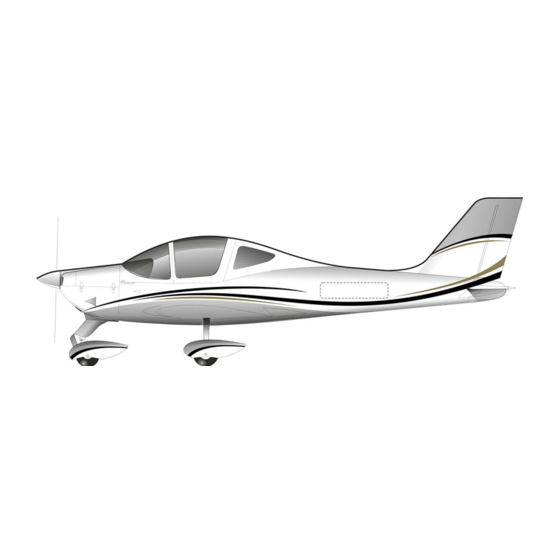
- Page 11 Page 1 - 3 HREE IEW AND IMENSIONS HREE Fig. 1.1 – General views Dimensions shown refer to normal operating tire pressure. Propeller ground clearance 320mm Propeller ground clearance with deflated front tire and nose wheel shock ab- ...
- Page 12 Page 1 - 4 IMENSIONS Overall dimensions Wingspan 8.6 m Length 6.61 m Overall height 2.43 m Wing Wing surface 11.5 m Taper Ratio Dihedral 5° Aspect ratio Main Landing Gear Track 1.85 m Wheelbase 1.62 m Tire (Air Trac) 5.00-5 Wheel hub and brakes (Cleveland) 199-102...
- Page 13 Page 1 - 5 ENERAL EATURES ONTROL URFACES RAVEL IMITS Ailerons Up 20° Down 15 ° ( 2°) Stabilator (refer to Trailing Edge) Up 3° Down 15° ( 1°) Stabilator trim tab (refer to Trailing Edge) Up 2°; Down 9° ( 1°) Rudder RH 30°...
- Page 14 Page 1 - 6 Approved fuel: MOGAS ASTM D4814 MOGAS EN 228 Super/Super Plus (Min RON 95) AVGAS 100LL (ASTM D910) (see also Section 2) Two wing tanks integrated within the wing’s Fuel tanks leading edge. Equipped with finger strainers outlet and with drain fittings.
- Page 15 Page 1 - 7 PECIFIC LOADINGS MTOW 580 kg MTOW 600 kg MTOW 620 kg Wing Loading 50.4 kg/m 52.2 kg/m 53.9 kg/m Power Loading 5.9 kg/hp 6.1 kg/hp 6.3 kg/hp Reference is made to each MTOW: 580 kg, 600 kg (if Supplement NOTE A11 Increased MTOW @600kg is applicable) and 620 kg (if Sup- plement A12 Increased MTOW @620kg is applicable).
- Page 16 Page 1 - 8 CRONYMS AND TERMINOLOGY ENERAL IRSPEED ERMINOLOGY YMBOLS KCAS Calibrated Airspeed is the indicated airspeed expressed in knots, corrected taking into account the errors related to the instrument itself and its installation. KIAS Indicated Airspeed is the speed shown on the airspeed indicator and it is expressed in knots.
- Page 17 Page 1 - 9 ETEOROLOGICAL TERMINOLOGY International Standard Atmosphere: is the air atmospheric standard condition at sea level, at 15°C (59°F) and at 1013.25hPa (29.92inHg). Official atmospheric pressure at airport level: it indicates the air- craft absolute altitude with respect to the official airport level. Theoretical atmospheric pressure at sea level: is the atmospheric pressure reported at the medium sea level, through the standard air pressure-altitude relationship, starting from the airport QFE.
- Page 18 Page 1 - 10 IRCRAFT PERFORMANCE AND FLIGHT PLANNING TERMINOLOGY Crosswind Velocity is the velocity of the crosswind component for the which adequate control of the air- plane during takeoff and landing is assured. Usable fuel is the fuel available for flight planning. Unusable fuel is the quantity of fuel that cannot be safely used in flight.
- Page 19 Maximum Takeoff Weight is the maximum weight approved to perform the takeoff. Maximum Landing Weight is the maximum weight approved for the landing touchdown (for P2002-JF it is equivalent Maximum Takeoff Weight). Tare is the weight of chocks, blocks, stands, etc.
-
Page 20: Unit Conversion Chart
Page 1 - 12 NIT CONVERSION CHART MOLTIPLYING YIELDS EMPERATURE Fahrenheit [°F] Celsius [°C] [°F] Celsius [°C] Fahrenheit ORCES Kilograms [kg] 2.205 Pounds [lbs] Pounds [lbs] 0.4536 Kilograms [kg] PEED... - Page 21 Page 1 - 13 / US ITRES GALLONS CONVERSION CHART Litres US Gallons US Gallons Litres 11.4 15.1 22.7 30.3 37.9 10.6 45.4 11.9 53.0 13.2 60.6 15.9 68.1 18.5 75.7 21.1 83.3 23.8 90.9 26.4 98.4 29.1 106.0 31.7 113.6 34.3 121.1...
- Page 22 Page 1 - 14 INTENTIONALLY LEFT BLANK Edition, Rev 0 Section 1 – General...
- Page 23 Page 2 - 1 SECTION 2 – LIMITATIONS INDEX 1. Introduction ..............2 2. Speed limitations .............. 3 3. Airspeed indicator markings ..........4 4. Powerplant limitations ............. 5 5. Lubricant ................6 6. Coolant liquid ..............7 7. Propeller ................8 8.
- Page 24 Page 2 - 2 1. I NTRODUCTION Section 2 includes operating limitations, instrument markings and basic placards necessary for safe operation of P2002-JF aircraft, its engines and standard systems and equipment. Edition, Rev. 0 Section 2 – Limitations INTRODUCTION...
- Page 25 Page 2 - 3 2. S PEED LIMITATIONS The following table addresses the airspeed limitations and their operational signifi- cance: SPEED KIAS KCAS REMARKS V NE Never exceed speed Do not exceed this speed in any operation. V NO Maximum Structural Cruising Do not exceed this speed Speed except in smooth air, and...
- Page 26 Page 2 - 4 3. A IRSPEED INDICATOR MARKINGS Airspeed indicator markings and their colour code are explained in the following table. MARKING KIAS EXPLANATION 30 – 67 White arc Positive Flap Operating Range (lower limit is V , at specified maximum weight and upper limit is the maximum speed permissi- ble with landing flaps extension).
- Page 27 Page 2 - 5 4. P OWERPLANT LIMITATIONS Following table reports the operating limitations for aircraft engine installed: : Bombardier Rotax GmbH. NGINE MANUFACTURER : 912 S2 NGINE MODEL AXIMUM POWER Max Power Max rpm. Time max. kW (hp) Prop. rpm (engine) (minutes) 73.5 (98.5) 2388 (5800)
- Page 28 Page 2 - 6 5. L UBRICANT Use viscosity grade oil as specified in the following table: Use of Aviation Grade Oil with or without additives is not per- mitted WARNING Edition, Rev. 0 Section 2 – Limitations LUBRICANT...
- Page 29 Page 2 - 7 6. C OOLANT LIQUID Coolant type and specifications are detailed into the “Rotax Operator’s Manual” and in its related documents. Edition, Rev. 0 Section 2 – Limitations COOLANT LIQUID...
- Page 30 Page 2 - 8 7. P ROPELLER MANUFACTURER: Hoffmann Propeller GmbH MODEL: HO17GHM A 174 177 C TYPE: Wood twin blade fixed pitch DIAMETER: 1740 mm (no reduction permitted) Edition, Rev. 0 Section 2 – Limitations PROPELLER...
- Page 31 Page 2 - 9 8. M AXIMUM OPERATING ALTITUDE Maximum operating altitude is 14000 ft (4260 m) MSL. At altitudes above 12500 ft (3810 m) up to and including 14000 ft (4260 m), flight must be limited to 30 minutes, unless the required mini- mum flight crew is provided with and uses supplemental oxygen for that CAUTION part of the flight at those altitudes that is of more than 30 minutes dura-...
- Page 32 Page 2 - 10 9. A MBIENT TEMPERATURE Ambient temperature: from -25°C to +50°C. Flight in expected and/or known icing conditions is forbidden. WARNING Edition, Rev. 0 Section 2 – Limitations AMBIENT TEMPERATURE...
- Page 33 Page 2 - 11 10. P OWERPLANT INSTRUMENTS MARKINGS Powerplant instrument markings and their colour code significance are shown be- low: RED LINE GREEN ARC YELLOW ARC RED LINE Minimum Normal Caution Maximum NSTRUMENT limit operating limit Propeller ---- 580 - 2265 2265 - 2388 2388 Oil temp.
- Page 34 Page 2 - 12 11. O THER INSTRUMENTS MARKINGS RED LINE GREEN ARC YELLOW ARC RED LINE NSTRUMENT Minimum limit Normal operating Caution Maximum limit Voltmeter 10,5 Volt 12 - 14 Volt ---- ---- 4,5 – 5,5 inHg Suction Gage 4,0 inHg ---- ----...
- Page 35 Page 2 - 13 12. W EIGHTS Condition Weight Maximum take-off weight 580 kg Maximum landing weight 580 kg Maximum zero wing fuel weight 580 kg Maximum baggage weight (2.26 m aft from datum): 20 kg 13. C ENTER OF GRAVITY RANGE Datum Propeller support flange without spacer Levelling...
- Page 36 Page 2 - 14 14. A PPROVED MANEUVERS The aircraft is certified in normal category in accordance with EASA CS-VLA regula- tion. Non aerobatic operations include: Any manoeuvre pertaining to “normal” flight Stalls (except whip stalls) Lazy eights ...
- Page 37 Page 2 - 15 16. F LIGHT CREW Minimum crew for flight is one pilot seated on the left side. 17. M AXIMUM PASSENGER SEATING With the exception of the pilot, only one passenger is allowed on board of this aircraft.
- Page 38 Page 2 - 16 18. K INDS OF PERATION QUIPMENT This paragraph reports the KOEL table, concerning the equipment list required on board under CS-VLA regulations to allow flight operations in VFR Day. Flight in VFR Day is permitted only if the pre-scribed equipment is installed and operational.
- Page 39 Page 2 - 17 19. F 50 liters each WO TANKS 100 liters. OTAL FUEL CAPACITY 99 liters SABLE FUEL Q 0.5 liters each (1.0 litres total) NUSABLE FUEL Q Compensate uneven fuel tank levels by acting on the fuel selector valve located into the cabin.
- Page 40 Page 2 - 18 20. D EMONSTRATED ROSS PERATIONS The aircraft controllability during take-offs and landings has been demonstrated with a cross wind components of 22 kts. Edition, Rev. 0 Section 2 – Limitations DEMONSTRATED CROSS WIND SAFE OPERATIONS...
- Page 41 Page 2 - 19 INTENTIONALLY LEFT BLANK Edition, Rev. 0 Section 2 – Limitations DEMONSTRATED CROSS WIND SAFE OPERATIONS...
- Page 42 Page 2 - 20 21. L IMITATION LACARDS The following limitation placards must be placed in plain view on the aircraft. Near the airspeed indicator a placard states the following: MANEUVERING SPEED V = 96 KIAS On the left hand side of the dashboard a placard states the following: HIS AIRPLANE IS CLASSIFIED AS A VERY LIGHT AIRPLANE AP- PROVED FOR DAY VFR ONLY IN NON...
- Page 43 Page 2 - 21 INTENTIONALLY LEFT BLANK Edition, Rev. 0 Section 2 – Limitations LIMITATION PLACARDS...
- Page 44 Page 2 - 22 INTENTIONALLY LEFT BLANK Edition, Rev. 0 Section 2 – Limitations LIMITATION PLACARDS...
- Page 45 Page 3 - 1 SECTION3–EMERGENCY PROCEDURES INDEX Introduction ................3 Airplane alerts ................4 2.1. Electric Power System Malfunction ..........4 2.2. Electrical fuel pump Failure ............5 2.3. Trim System Failure ............... 5 2.4. Airplane evacuation ................ 5 Engine securing ................. 6 Engine Failure ................
- Page 46 Page 3 - 2 INTENTIONALLY LEFT BLANK Edition, Rev. 0 Section 3 – Emergency procedures INDEX...
- Page 47 Page 3 - 3 1. I NTRODUCTION Section 3 includes checklists and detailed procedures to be used in the event of emergencies. Emergencies caused by a malfunction of the aircraft or engine are extremely rare if appropriate maintenance and pre-flight inspections are carried out.
- Page 48 Page 3 - 4 2. A IRPLANE ALERTS The alert lights, located on the instrument panel can have the following colours: GREEN: to indicate that pertinent device is turned ON AMBER: to indicate no-hazard situations which have to be considered and which require a proper crew action 2.1.
- Page 49 Page 3 - 5 2.2. LECTRICAL FUEL PUMP AILURE If the electrical fuel pump light is OFF the reasons can be: Electrical fuel pump not electrically fed Light inoperative Apply the following procedure: Electrical fuel pump switch: Electrical fuel pump switch: Fuel pressure: CHECK raise If fuel pressure doesn’t build up:...
- Page 50 Page 3 - 6 NGINE SECURING Following procedure is applicable to shut-down the engine in flight: 1. Throttle Lever IDLE Magnetos 3. Fuel Selector 4. Electrical fuel pump 5. Generator switch Edition, Rev. 0 Section 3 – Emergency procedures Engine securing...
- Page 51 Page 3 - 7 4. E NGINE AILURE 4.1. NGINE AILURE URING Throttle: IDLE (fully out) Rudder Keep heading control Brakes: apply as needed When safely stopped: Magnetos: OFF. Fuel selector valve: Electric fuel pump: Generator & Master switches: OFF. 4.2.
- Page 52 Page 3 - 8 4.3. NGINE AILURES URING LIGHT 4.3.1 Low Fuel Pressure If the fuel pressure indicator falls below the 2.2 psi(0.15 bar): Electric fuel pump: Fuel selector valve: change the fuel feeding tank Check both fuel quantity indicators If fuel pressure doesn’t build up: Land as soon as possible monitoring fuel pressure.
- Page 53 Page 3 - 9 4.3.3 High Oil Temperature If oil pressure is low see para. 4.3.2 Low Oil Pressure. If oil pressure is within limits: Throttle Lever REDUCE Minimum practical If oil temperature does not decrease Airspeed INCREASE If oil temperature does not come back within limits, the thermostatic valve (if embodied), regulating the oil NOTE flow to the heat exchangers, could be damaged or an...
- Page 54 Page 3 - 10 4.3.4 CHT limit exceedance If CHT is above 135°C: Throttle Lever REDUCE Minimum practical Land as soon as practical If CHT continues to rise and engine shows roughness or power loss: Land as soon as possible applying forced landing procedure (See Para. 7) Edition, Rev.
- Page 55 Page 3 - 11 5. I LIGHT NGINE ESTART After a mechanical engine seizure, fire or a major propeller damage engine restart is not recommended. WARNING It is preferred to restart the engine at an altitude below 4000ft and at NOTE the suggested speed of 69 KIAS or more Carburettor heat...
- Page 56 Page 3 - 12 6. S MOKE 6.1. NGINE FIRE ON THE GROUND Fuel Selector Electrical fuel pump Magnetos Throttle lever FULL POWER Cabin Heat Generator & Master Switches Parking Brake ENGAGED Aircraft Evacuation carry out immediately 6.2. NGINE URING AKEOFF BEFORE ROTATION: ABORT TAKE OFF Throttle Lever...
- Page 57 Page 3 - 13 6.3. NGINE LIGHT Cabin heating: Fuel selector valve: Electric fuel pump: Throttle: FULL FORWARD until the engine stops Magnetos: Cabin vents: OPEN Do not attempt engine restart WARNING Land as soon as possible applying forced landing procedure(See Para. 7). 6.4.
- Page 58 Page 3 - 14 7. L ANDING MERGENCY 7.1. ORCED ANDING ITHOUT NGINE OWER Flap: Airspeed: 69 KIAS Find a suitable place to land safely, plan to approach it upwind. Fuel selector valve: Electric fuel pump: Magnetos: Safety belts: Tighten Canopy locks: CHECK LOCKED When certain to land...
- Page 59 Page 3 - 15 7.4. ANDING If it’s suspected a main tire defect or it’s reported to be defective: 1. Pre-landing checklist: Complete 2. Flaps: Land 3. Land the aeroplane on the side of runway opposite to the defective tire to compensate the change in direction which is to be expected during final rolling 4.
- Page 60 Page 3 - 16 8. R ECOVERY NINTENTIONAL If unintentional spin occurs, the following recovery procedure should be used: Throttle: IDLE (full out position) Rudder: full, in the opposite direction of the spin Stick: centralize and hold neutral As the spin stops: Rudder: SET NEUTRAL Aeroplane attitude:...
- Page 61 Page 3 - 17 9. O THER MERGENCIES 9.1. NINTENTIONAL LIGHT CING ONDITIONS Carburettor ice is possible when flying at low engine rpm in visi- ble moisture (outside visibility less than 5 km, vicinity of fog, mist, clouds, rain, snow or hail) and OAT less than 10°C.Airbox carbu- rettor heater is designed to help prevent carburettor ice, less ef- WARNING fectively functions as a de-icing system.
- Page 62 Page 3 - 18 INTENTIONALLY LEFT BLANK Edition, Rev. 0 Section 3 – Emergency Procedures OTHER EMERGENCIES...
- Page 63 Page 4 - 1 SECTION 4 – NORMAL PROCEDURES INDEX 1. Introduction ................2 2. Airspeeds for normal operations ..........2 3. Pre-Flight Inspections .............. 3 3.1. Cabin Inspection ..................3 3.2. Aircraft walk-around ................3 4. Checklists ................. 7 4.1.
- Page 64 Page 4 - 2 1. I NTRODUCTION Section 4 contains checklists and the procedures for the conduct of normal oper- ation. 2. A IRSPEEDS FOR NORMAL OPERATIONS Following airspeeds are significant for normal operations, with reference to each MTOW: 580 kg, 600 kg (if Supplement A11 - Increased MTOW @600 KG - is applicable) and 620 kg (if Supplement A12 - Increased MTOW @620 KG - is applicable).
- Page 65 Page 4 - 3 3. P LIGHT NSPECTIONS Before each flight, it is necessary to carry out a complete aircraft check com- prising an external inspection followed by a cockpit inspection as below de- tailed. 3.1. ABIN NSPECTION Aircraft documents (ARC, Certificate of Airworthiness, Noise certificate, Radio COM certificate, AFM): check current and on board Weight and balance: calculate (ref.
- Page 66 Page 4 - 4 FIG. 4-1 A Left fuel filler cap: check visually for desired fuel level. Drain the left fuel tank by drainage valve using a cup to collect fuel (drainage operation must be carried out with the aircraft parked on a level surface). Check for water or other contaminants.
- Page 67 Page 4 - 5 Right main landing gear; check inflation, tire condition, alignment, fuse- lage skin condition. Right flap and hinges: visual inspection. M Right aileron, trim tab and hinges: visual inspection, check free of play, friction; Right side tank vent: check for obstructions. N Right leading edge and wing skin: visual inspection.
- Page 68 Page 4 - 6 Check oil level and replenish as required. Prior to oil check, having magnetos switched off turn the propeller by hand in direction of engine rotation several times to pump oil from the engine into the oil tank, or let the engine idle for 1 minute.
- Page 69 Page 4 - 7 HECKLISTS 3.3. EFORE NGINE TARTING FTER REFLIGHT NSPECTION Seat position and safety belts adjustment Flight controls: operate until their stop checking for movement smoothness, free of play and friction. Parking brake: engage and brake pedal press/brake lever pull Throttle friction: adjust Circuit Breakers: check all IN Master switch: ON, Check generator light ON and Voltage (at least...
- Page 70 Page 4 - 8 3.4. NGINE TARTING Master switch ON. Engine throttle: idle Choke: as needed Fuel selector valve: select the tank with less fuel Electric fuel pump: ON Propeller area: call for CLEAR and visually check Check to insure no person or object is present in the area close to the propeller.
- Page 71 Page 4 - 9 3.6. AXIING Brakes: check Steering: check Flight instruments: check altimeter and variometer, artificial horizon aligne- ment, gyro compass and turn indicator coherent with steering direction, balance ball free into the opposite direction. 3.7. RIOR Parking brake: ON, brake pedal press / brake lever pull Engine instruments: Check within limits •...
- Page 72 Page 4 - 10 3.8. LIMB On uncontrolled fields, before line up, check runway wind direc- tion and speed and check for traffic on final WARNING Parking brake: OFF Carburetor heat: OFF Check magnetic compass and gyro direction indicator alignment ±...
- Page 73 Page 4 - 11 3.9. RUISE Set power at or below maximum continuous: 2250 propeller rpm Check engine instruments within limits Carburettor heat as needed, see paragraph on carb. heat in Section 3. Monitor and manually compensate asymmetrical fuel consump- NOTE tion by switching fuel selector valve.
- Page 74 Page 4 - 12 3.12. FTER ANDING Flaps: UP Electric Fuel Pump: OFF Landing light: OFF 3.13. NGINE Parking brake: engage Keep engine running at 1200 rpm for about one minute in order to reduce la- tent heat. Avionic equipment: OFF Magnetos: OFF, keys extracted Strobe light: OFF Master &...
- Page 75 Page 5 - 1 SECTION 5 - PERFORMANCES INDEX 1. INTRODUCTION ................2 2. USE OF PERFORMANCES CHARTS ..........3 3. AIRSPEED INDICATOR SYSTEM CALIBRATION ..4 APPROVED DATA 4. ICAO STANDARD ATMOSPHERE ............. 5 5. STALL SPEED ............6 APPROVED DATA 6.
- Page 76 Page 5 - 2 1. I NTRODUCTION This section provides all necessary data for an accurate and comprehensive plan- ning of flight activity from takeoff to landing. Data reported in graphs and/or in tables were determined using: “Flight Test Data” under conditions prescribed by EASA CS-VLA regulation ...
- Page 77 Page 5 - 3 2. U SE OF PERFORMANCES CHARTS Performances data are presented in tabular or graphical form to illustrate the effect of different variables such as altitude, temperature and weight. Given information is sufficient to plan the mission with required precision and safety. Additional information is provided for each table or graph.
- Page 78 Page 5 - 4 3. A Approved Data IRSPEED INDICATOR SYSTEM CALIBRATION Graph shows calibrated airspeed V as a function of indicated airspeed V CALIBRATED AIRSPEED [KCAS] . 5-1. C ALIBRATED VS NDICATED IRSPEED Example: Given Find KIAS 75 KCAS 74 NOTE Indicated airspeed assumes 0 as an instrument error Edition, Rev.
- Page 79 Page 5 - 5 4. ICAO S TANDARD TMOSPHERE . 5-2. ICAO C HART Examples: Scope Given Find A: Pressure altitude = 1600ft → C: Density Altitude = 2550ft Density Altitude: B: Temperature = 20°C → E: ISA Air Temperature = 12°C ISA Temperature: D: Pressure altitude = 1600ft Edition, Rev.
- Page 80 Page 5 - 6 5. S Approved Data TALL SPEED Weight: 580 kg Throttle Levers: IDLE CG: Most Forward (26%) No ground effect TALL PEED EIGHT NGLE 0° LAPS LAPS LAPS [kg] [deg] KIAS KCAS KIAS KCAS KIAS KCAS (FWD C.G.) Altitude loss during conventional stall recovery, as demonstrated NOTE during flight tests is approximately 150 ft with banking below 30°.
- Page 81 Page 5 - 7 6. C ROSSWIND Maximum demonstrated crosswind is 22 Kts Example: Given Find Wind direction ( ) = 30° Headwind = 17.5 Kts with respect to aircraft longitudinal axis Wind speed = 20 Kts Crosswind = 10 Kts .
- Page 82 Page 5 - 8 7. T Approved Data OFF PERFORMANCES Weight = 580 kg Corrections Headwind: - 2.5m for each kt (8 ft/kt) Flaps: T/O Tailwind: + 10m for each kt (33ft/kt) Speed at Lift-Off = 42 KIAS Speed Over 50ft Obstacle = 52 KIAS Paved Runway: - 6% to Ground Roll Throttle Levers: Full Forward Runway slope: + 5% to Ground Roll for each +1%...
- Page 83 Page 5 - 9 Weight = 550 kg Corrections Headwind: - 2.5m for each kt (8 ft/kt) Flaps: T/O Tailwind: + 10m for each kt (33ft/kt) Speed at Lift-Off = 42 KIAS Speed Over 50ft Obstacle = 52 KIAS Paved Runway: - 6% to Ground Roll Throttle Levers: Full Forward Runway slope: + 5% to Ground Roll for each +1% Runway: Grass...
- Page 84 Page 5 - 10 Weight = 500 kg Corrections Headwind: - 2.5m for each kt (8 ft/kt) Flaps: T/O Tailwind: + 10m for each kt (33ft/kt) Speed at Lift-Off = 42 KIAS Speed Over 50ft Obstacle = 52 KIAS Paved Runway: - 6% to Ground Roll Throttle Levers: Full Forward Runway slope: + 5% to Ground Roll for each +1% Runway: Grass...
- Page 85 Page 5 - 11 8. T ATE OF LIMB Power Setting: Maximum Continuous Power Flaps: Take-Off (15°) Climb Rate of Climb [ft/min] Pressure Weight Speed Altitude Temperature [°C] [kg] [ft] [KIAS] S.L. 1238 2000 1047 4000 6000 8000 -151 10000 -143 -327 12000...
- Page 86 Page 5 - 12 9. E OUTE ATE OF LIMB Power Setting: Maximum Continuous Power Flaps: UP Climb Rate of Climb [ft/min] Pressure Weight Speed Altitude Temperature [°C] [kg] [ft] [KIAS] S.L. 1362 1111 1000 1171 2000 3000 4000 5000 -203 6000 -198...
- Page 87 Page 5 - 13 10. C RUISE PERFORMANCES Weight: 580 kg Pressure Altitude: 0 ft ISA – 30°C (-15°C) ISA (15°C) ISA + 30°C (45°C) F.C. F.C. F.C. KTAS KTAS KTAS [lt/hr] [lt/hr] [lt/hr] 2361 120% 32.2 100% 26.8 22.6 2318 113% 30.5...
- Page 88 Page 5 - 14 Weight: 580 kg Pressure Altitude: 6000 ft ISA – 30°C (-15°C) ISA (15°C) ISA + 30°C (45°C) F.C. F.C. F.C. KTAS KTAS KTAS [lt/hr] [lt/hr] [lt/hr] 2340 26.5 21.8 2296 25.1 20.5 16.9 2249 23.6 19.2 15.7 2196 17.8...
- Page 89 Page 5 - 15 11. L Approved Data ANDING PERFORMANCES Weight = 580 kg Corrections Headwind: - 5m for each kt (16 ft/kt) Flaps: LAND Tailwind: + 11m for each kt (36ft/kt) Short Final Approach Speed = 51 KIAS Throttle Levers: Idle Paved Runway: - 2% to Ground Roll Runway: Grass Runway slope: - 2.5% to Ground Roll for each +1%...
- Page 90 Page 5 - 16 Weight = 550 kg Corrections Headwind: - 5m for each kt (16 ft/kt) Flaps: LAND Tailwind: + 11m for each kt (36ft/kt) Short Final Approach Speed = 51 KIAS Throttle Levers: Idle Paved Runway: - 2% to Ground Roll Runway: Grass Runway slope: - 2.5% to Ground Roll for each +1% Pressure...
- Page 91 Page 5 - 17 Weight = 500 kg Corrections Headwind: - 5m for each kt (16 ft/kt) Flaps: LAND Tailwind: + 11m for each kt (36ft/kt) Short Final Approach Speed = 51 KIAS Throttle Levers: Idle Paved Runway: - 2% to Ground Roll Runway: Grass Runway slope: - 2.5% to Ground Roll for each +1% Pressure...
- Page 92 Page 5 - 18 12. B ALKED ANDING LIMB Power Setting: Maximum Take-Off Power Flaps: Land (40°) : 51 KIAS Rate of Climb [ft/min] Pressure Weight Altitude Temperature [°C] [kg] [ft] S.L. 1000 2000 3000 4000 5000 6000 7000 S.L. 1000 2000 3000...
- Page 93 Page 5 - 19 13. N OISE DATA Noise level, determined in accordance with ICAO/Annex 16 4th Ed., July 2005, Vol. I°, Chapter 10, is 62.36 dB(A). Edition, Rev. 0 Section 5 - Performances NOISE DATA...
- Page 94 Page 5 - 20 INTENTIONALLY LEFT BLANK Edition, Rev. 0 Section 5 - Performances...
- Page 95 Page 6 - 1 SECTION6–WEIGHT and BALANCE INDEX 1. INTRODUCTION ................2 2. WEIGHING PROCEDURES ..............3 2.1. PREPARATION ................ 3 2.2. LEVELLING ................3 2.3. WEIGHING ................3 2.4. DETERMINATION OF C.G. LOCATION ........3 3. WEIGHING REPORT (I) ..............5 4.
- Page 96 Page 6 - 2 1. I NTRODUCTION This section describes the procedure for establishing the basic empty weight and the moment of the aircraft. Loading procedure information is also provided. Aircraft must be operated in accordance with the limits con- NOTE cerning the maximum take-off weight and CG excursion as re- ported in Flight Manual Section 2.
- Page 97 Page 6 - 3 2. W EIGHING PROCEDURES 2.1. REPARATION Carry out weighing procedure inside closed hangar Remove from cabin any objects left unintentionally Insure on board presence of the Flight Manual Align nose wheel Drain fuel via the specific drain valve.
- Page 98 Page 6 - 4 MAC 1370 15 mm inboard from rib n°7 1337 from the propeller's flange (without sapacer) Reference line W2 * A - W1 * B W1 + W2 D% = * 100 W2=WL+WR 1370 Fig.6.1 Edition, Rev 0 Section 6 –...
- Page 99 Page 6 - 5 3. W EIGHING EPORT ModelP2002-JFS/N:________ Weighing no. ____ Date:_________ Datum: Propeller support flange without spacer. 1337 Datum Reference line W2 * A - W1 * B W1 + W2 D% = * 100 W2=WL+WR 1370 meters Nose wheel weight Plumb bob distance LH wheel...
- Page 100 Page 6 - 6 4. W (II) EIGHING EPORT ModelP2002-JFS/N:________ Weighing no. ____ Date:_________ Datum: Propeller support flange without spacer. 1337 Datum Reference line W2 * A - W1 * B W1 + W2 D% = * 100 W2=WL+WR 1370 meters Nose wheel weight Plumb bob distance...
- Page 101 Page 6 - 7 5. W EIGHT ALANCE To determine the aircraft's CG location and to verify that the CG lies within the predetermined CG travel range, it would be helpful to use the chart in the fol- lowing page. Chart reports CG location as a function of the empty weight mo- ment with respect to the datum as yielded by weighing report.
- Page 102 Page 6 - 8 MTOW = 580kg MTOW = 600kg MTOW = 620kg Moment (empty) - Kg m Edition, Rev 0 Section 6 – Weight and Balance WEIGHT AND BALANCE...
- Page 103 Page 6 - 9 Fig 6.3 C.G. RANGE CHART Fig 6.4 L OAD POSITION WITH RESPECT TO ATUM Edition, Rev 0 Section 6 – Weight and Balance WEIGHT AND BALANCE...
- Page 104 Page 6 - 10 6. L UGGAGE Luggage compartment is designed for a maximum load of 20 kg. Luggage size shall prevent excessive loading of utility shelf (maximum pressure 12.5 kg/dm Maximum Luggage size is: 80x45x32 cm. Luggage must be secured using a tie- down net to prevent any luggage movement during maneuvers.
- Page 105 Page 6 - 11 7. E QUIPMENT The following is a comprehensive list of all TECNAM supplied equipment for the P2002-JF. The list consists of the following groups: A Engine and accessories Landing gear Electrical system D Instruments Avionics the following information describes each listing: ...
- Page 106 Page 6 - 12 EQUIPMENT LIST EIGHT ATUM & ESCRIPTION [kg] & NGINE ACCESSORIES Engine Rotax 912S2 - p/n 309.120.133 61.0 0.32 Prop. HOFFMANN – p/n HO17GHM A 174 177C -0.13 Exhaust and manifolds –p/n SSB-978-480-CC 4.50 0.55 Heat exchanger - p/n 92-11-830 2.00 0.55 Oil Reservoir (full) - p/n 956.137...
- Page 107 Page 6 - 13 EQUIPMENT LIST EIGHT ATUM & ESCRIPTION [kg] NSTRUMENTS Altimeter United Instruments p/n 5934PM-3 or LUN 0.39 1.35 1128.10B4 –TSO C10b Anemometro – MIKROTECHINA 1106.B0B2 0.30 1.35 Compass - Airpath C2400 L4P 0.29 1.35 Clock – DAVTRON mod. M 800 0.15 1.35 Vertical speed indicator –...
- Page 108 Page 6 - 14 EQUIPMENT LIST EIGHT ATUM & ESCRIPTION [kg] First Aid Kit 0.28 2.30 Altitude Encoder- Amery King Ak-30 0.25 1.00 Emergency Hammer-Dmail 108126 0.35 2.30 ADF Bendix King KR87 1.38 1.35 ADF Antenna Bendix King KA44B 1.89 2.05 Comm Garmin SL40 1.50...
- Page 109 Page 7 - 1 SEZIONE 7 – AIRFRAME AND SYSTEMS DESCRIPTION INDEX 1. Introduction ..................2 2. Airframe ................... 2 2.1. Wing ..................2 2.2. Fuselage ................. 2 2.3. Empennages ................2 3. F ................3 LIGHT ONTROLS 4. I ................
- Page 110 Page 7 - 2 1. Introduction This section provides description and operation of the aircraft and its systems. 2. Airframe 2.1. The wing consists of a central light alloy torque box; an aluminium leading edge with integrated fuel tank is attached to the front spar while flap and ailerons are hinged to rear spar.
-
Page 111: Flight Controls
Page 7 - 3 3. F LIGHT ONTROLS Aircraft flight controls are operated through conventional stick and rudder pedals. Longitudinal control acts through a system of push-rods and is equipped with a trim tab. Aileron control is of mixed type with push-rods and cables; the cable control circuit is confined within the cabin and is connected to a pair of push-rods positioned in the wings that control ailerons differentially. -
Page 112: Instrument Panel
Page 7 - 4 4. I NSTRUMENT ANEL The conventional type instrument panel allows placement of a broad range of equipment. Instruments marked with an asterisk (*) are optional. Fig. 7-2. I NSTRUMENT ANEL 4.1. ARBURETTOR Carburettor heat control knob is located on the left of the pedestal; when the knob is pulled fully outward from the instrument panel, carbs receive maximum hot air. - Page 113 Page 7 - 5 5. S EATS AFETY ARNESS Aircraft features four point fitting safety belts with waist and shoulder harnesses adjustable via sliding metal buckle. Seats are built with light alloy tube structure and synthetic material cushioning. A lever located on the right lower side of each seat allows for seat adjustment ac- cording to pilot size.
- Page 114 Page 7 - 6 6. C ANOPY The cabin's canopy slides on wheel bearings along tracks located on fuselage sides; canopy is made out of composite material. Latching system uses a central lever located overhead and two additional levers positioned on canopy's sides. The canopy could be opened both from in and outside.
- Page 115 Page 7 - 7 7. L UGGAGE OMPARTMENT The Luggage compartment is located behind the pilots' seats. Luggage shall be uniformly distributed on utility shelf and its weight shall not exceed 20kg. Tie-down luggage using adjustable tie-down net. Before loading luggage, check aircraft's weight and CG location (see Sect.
- Page 116 Page 7 - 8 8. P OWERPLANT 8.1. ENGINE Manufacturer: Bombardier-Rotax GmbH Model: ROTAX 912 S2 Type: 4 stroke, horizontally-opposed 4 cylinder, mixed air and water cooled, twin electronic ignition, forced lubrication. Maximum rating: 98.6hp (73.5kW) @ 5800 rpm/min (2388 rpm/min. prop). Gear reduction ratio - 2.4286:1 Max oil consumption: Max: 0.1 litres/hour 8.2.
-
Page 117: Fuel System
Page 7 - 9 9. F YSTEM The system is equipped with two aluminium fuel tanks integrated within the wing leading edge and accessible for inspection through dedicated covers. Capacity of individual tank is 50lt and the total fuel capacity is 100lt. A multi-position fuel se- lector valve is located into the cabin. -
Page 118: Electrical System
Page 7 - 10 10. E LECTRICAL YSTEM The aircraft's electrical system consists of a 12 Volt DC circuit controlled by the Master Switch located on the instrument panel. Electrical power is provided by an alternator and by a buffer battery. Generator light is located on the right side of the instrument panel. - Page 119 Page 7 - 11 10.2. OLTMETER AND MMETER The voltmeter indicates voltage on bus bar. A positive ammeter indication warns that the generator is charging the battery, a negative value indicates the battery's discharge rate. 10.3. . - O IL AND CYLINDER HEADS TEMP IL PRESSURE These instruments are connected in series with their respective sensors.
- Page 120 Page 7 - 12 11. P ITOT TATIC RESSURE YSTEMS The airspeed indicator system for the aircraft is shown below. Below the left wing’s leading edge are positioned in a single group (1) both the Pitot tube (3, total pressure intake) and a series of static ports (6). Two flexible hoses (5) feed the airspeed indicator (4) on the instrument panel.
- Page 121 Page 7 - 13 12. B RAKES The aircraft's braking system is a single system acting on both wheels of main land- ing gear through disk brakes, the same circuit acts as parking brake via an intercept valve (2). To activate brakes it is sufficient to verify that brake shut-off valve (2) positioned on tunnel between pilots is OFF, then activate brake lever (1) as necessary.
- Page 122 Page 7 - 14 INTENTIONALLY LEFT BLANK Edition, Rev 0 Section 7 – Airframe and Systems description Brakes...
- Page 123 Page 8 - 1 SECTION 8 – GROUND HANDLING & SERVICE INDEX 1. Introduction ..............2 2. Aircraft Inspection Intervals ........3 3. Aircraft Alterations or Repairs ........4 4. Ground Handling ............5 4.1. Towing ................5 4.2. Parking and Tie-Down ............ 5 4.3.
- Page 124 Page 8 - 2 1. I NTRODUCTION This section contains factory-recommended procedures for proper ground han- dling and routine care and servicing. It also identifies certain inspection and maintenance requirements, which must be followed if the aircraft is to retain its new-plane performance and dependability.
- Page 125 Page 8 - 3 2. A IRCRAFT NSPECTION NTERVALS Inspection intervals occur at 100 hours or at 1 year (whichever occurs first) and in accordance with special inspection schedules which are added to regularly scheduled inspections. Correct maintenance procedures are described in the air- craft’s Maintenance Manual or in the engine’s Maintenance Manual.
- Page 126 Page 8 - 4 3. A IRCRAFT HANGES OR EPAIRS Aircraft changes or repairs must be performed in accordance with Aircraft Maintenance Manual and only by TECNAM authorized personnel. Edition, Rev. 0 Section 8 – GROUND HANDLING & SERVICE AIRCRAFT CHANGES OR REPAIRS...
- Page 127 Page 8 - 5 4. G ROUND ANDLING 4.1. OWING The aircraft is most easily and safely maneuvered by pulling it by its propeller near the axle. Aircraft may be steered by turning rudder or, for steep turns, by pushing lightly on tailcone to lift nose wheel. 4.2.
- Page 128 Page 8 - 6 5. C LEANING To clean painted surfaces, use a mild detergent such as shampoo normally used for car finish; use a soft cloth for drying The plastic windshield and windows should never be dusted when dry; use lukewarm soapy water and dry using chamois only.
- Page 129 Page 8 - 7 6. E NGINE OWLING HECK 5.1. PPER COWLING Parking brake: ON Fuel selector valve: OFF III. Magnetos: OFF Generator & Master switches: OFF Unlatch all four butterfly Cam-locks mounted on the cowling by rotat- ing them 90° counter clockwise while slightly pushing inwards. Remove engine cowling paying attention to propeller shaft passing through nose.
- Page 130 Page 8 - 8 INTENTIONALLY LEFT BLANK Edition, Rev. 0 Section 8 – Aircraft Care and Maintenance ENGINE COWLING CHECK...
- Page 131 Page 9-1 SECTION 9 – SUPPLEMENTS INDEX Introduction ......................2 Supplements lists ....................3 Edition, Rev. 0 Section 9 - Supplements...
- Page 132 Page 9-2 1. I NTRODUCTION This Section concerns the supplemental manuals of additional (or optional) instrumenta- tion equipping the P2002-JF. Edition, Rev. 0 Section 9 - Supplements SUPPLEMENTS LIST...
- Page 133 Page 9-3 2. S UPPLEMENTS LISTS Aircraft S/N: Registration marks: Date: APPLICABLE: Sup. No. Title Rev. no. Date Garmin GNS-430W Gps/VHF Comm/Nav GARMIN GPS/VHF COMM/NAV New analogical instruments panel Differential brake system Central throttle control system AFM supplement for CIS countries operators Garmin G500 Avionics Display System...
- Page 134 Page 9-4 INTENTIONALLY LEFT BLANK Edition, Rev. 0 Section 9 - Supplements SUPPLEMENTS LIST...
- Page 135 Page A01-1 . A01 UPPLEMENT NO GARMIN GNS 430 GPS/VHF COMM/NAV Record of Revisions EASA Approval Tecnam Approval Revised Description of or Under DOA page Revision Privileges List of Effective Pages Page Revision Page Revision Rev 0 Rev 0 A01-1...
- Page 136 Page A01-2 INDEX INTRODUCTION ..................3 GENERAL ....................3 LIMITATIONS ..................4 EMERGENCY PROCEDURES ..............5 NORMAL OPERATION ................5 PERFORMANCE ..................5 WEIGHT AND BALANCE................. 5 SYSTEMS ....................5 Edition, Rev. 0 Section 9 – Supplements Supplement no. A01 – GARMIN GNS 430 GPS/VHF COMM/NAV...
- Page 137 Page A01-3 NTRODUCTION This section contains supplementary information for safe and efficient operation of the aircraft if equipped with a Garmin GNS 430 system. ENERAL The GPS GNS 430 Global Positioning System is an integrated system that contains a GPS navigation system in addition to a VHF COMM radio transceiver and a VOR/ILS receiver.
- Page 138 Page A01-4 IMITATIONS The “Pilot’s guide and Reference” p/n 190-00140-00 rev. F dated July 2000 or later versions, must be available for proper use of the instrument. Only VFR use is permitted. The GPS section must use the following (or more recently approved) soft- ware versions: Subsystem Software Version...
- Page 139 Page A01-5 MERGENCY ROCEDURES If the information provided by the Garmin GNS430 is not available or manifestly wrong, it is necessary to use other navigation instruments. If the message “WARN” appears in the lower left portion of the display, the receiver cannot be considered useful as a navigation aid. The pilot must use the VLOC receiver or an alternative navigation system.
- Page 140 Page A01-6 INTENTIONALLY LEFT BLANK Edition, Rev. 0 Section 9 – Supplements Supplement no. A01 – GARMIN GNS 430 GPS/VHF COMM/NAV...
- Page 141 Page A02-1 . A02 UPPLEMENT NO GARMIN GNS 530 GPS/VHF COMM/NAV Record of Revisions EASA Approval Tecnam Approval Revised Description of or Under DOA page Revision Privileges List of Effective Pages Page Revision Page Revision Rev 0 Rev 0 A02-1...
- Page 142 Page A02-2 INDEX INTRODUCTION ..................3 GENERAL ....................3 LIMITATIONS ..................4 EMERGENCY PROCEDURES ..............5 NORMAL OPERATION ................5 PERFORMANCE ..................5 WEIGHT AND BALANCE................. 5 SYSTEMS ....................5 Edition, Rev. 0 Section 9 – Supplements Supplement no. A02 – GARMIN GNS 530 GPS/VHF COMM/NAV...
- Page 143 Page A02-3 NTRODUCTION This section contains supplementary information for safe and efficient operation of the aircraft if equipped with a Garmin GNS 530 system. ENERAL The GPS GNS 530 Global Positioning System is an integrated system that contains a GPS navigation system in addition to a VHF COMM radio transceiver and a VOR/ILS receiver.
- Page 144 Page A02-4 IMITATIONS The “Pilot’s guide and Reference” p/n 190-00181-00 rev. A dated April 2000 or later versions, must be available for proper use of the instrument. Only VFR use is permitted. The GPS section must use the following (or more recently approved) soft- ware versions: Subsystem Software Version...
- Page 145 Page A02-5 MERGENCY ROCEDURES If the information provided by the Garmin GNS530 is not available or manifestly wrong, it is necessary to use other navigation instruments. If the message “RAIM POSITION WARNING ” appears in the display, the receiver cannot be considered useful as a navigation aid. The pilot must use the VLOC receiver or an alternative navigation system.
- Page 146 Page A02-6 INTENTIONALLY LEFT BLANK Edition, Rev. 0 Section 9 – Supplements Supplement no. A02 – GARMIN GNS 530 GPS/VHF COMM/NAV...
- Page 147 Page A03-1 . A03 UPPLEMENT NO NALOGICAL NSTRUMENT ANEL Record of Revisions EASA Approval Tecnam Approval Revised Description of or Under DOA page Revision Privileges List of Effective Pages Page Revision Page Revision Rev 0 Rev 0 A03-1 A03-3 A03-2...
- Page 148 Page A03-2 INDEX INTRODUCTION ..................3 GENERAL ....................3 LIMITATIONS ..................3 EMERGENCY PROCEDURES ..............3 NORMAL OPERATION ................3 PERFORMANCE ..................3 WEIGHT AND BALANCE................. 3 SYSTEMS ....................4 Edition, Rev. 0 Section 9 – Supplements Supplement no. A03 – New Analogical Instrument Panel...
- Page 149 Page A03-3 NTRODUCTION This section contains supplementary information for safe and efficient operation of the aircraft if equipped with the new analogical instruments panel. ENERAL No variations. IMITATIONS No variations. MERGENCY ROCEDURES No variations. ORMAL PERATION No variations. ERFORMANCE No variations. EIGHT AND ALANCE No variations.
- Page 150 Page A03-4 YSTEMS The new analogical instruments panel is designed with a modular concept to im- prove the instruments visibility. The new instruments panel is divided into three main parts. The left part with the flight instruments, central part with the avionic instruments and the right part with the engine instruments.
- Page 151 Page A04-1 . A04 UPPLEMENT NO IFFERENTIAL RAKE YSTEM Record of Revisions EASA Approval Tecnam Approval Revised Description of or Under DOA page Revision Privileges List of Effective Pages Page Revision Page Revision Rev 0 Rev 0 A04-1 A04-3 A04-2...
- Page 152 Page A04-2 INDEX INTRODUCTION ..................3 GENERAL ....................3 LIMITATIONS ..................3 EMERGENCY PROCEDURES ..............3 NORMAL OPERATION ................3 PERFORMANCE ..................3 WEIGHT AND BALANCE................. 3 SYSTEMS ....................4 Edition, Rev. 0 Section 9 – Supplements Supplement no. A04 – Differential Brake System...
- Page 153 Page A04-3 NTRODUCTION This section contains supplementary information for safe and efficient operation of the aircraft if equipped with the differential brake system. ENERAL No variations. IMITATIONS No variations. MERGENCY ROCEDURES No variations. ORMAL PERATION No variations. ERFORMANCE No variations. EIGHT AND ALANCE No variations.
- Page 154 Page A04-4 YSTEMS Figure A04-2 shows the brake system schematic diagram. The left and right wheel brakes are independent systems. The system has a res- ervoir (4) on the co-pilot’s brake pedals (1). The reservoir is directly connected to the brake master cylinders (3). Two flexible hoses connect the master cylin- ders on the co-pilot’s brake pedals to the master cylinders on the pilot’s brake pedals.The parking brake valve (6) is mounted on the floor of the fuselage, be- low the seats and it’s activated by lever (2).
- Page 155 Page A05-1 . A05 UPPLEMENT NO ENTRAL HROTTLE ONTROL YSTEM Record of Revisions EASA Approval Tecnam Approval Revised Description of or Under DOA page Revision Privileges List of Effective Pages Page Revision Page Revision Rev 0 Rev 0 A05-1 A05-3...
- Page 156 Page A05-2 INDEX INTRODUCTION ..................3 GENERAL ....................3 LIMITATIONS ..................3 EMERGENCY PROCEDURES ..............3 NORMAL OPERATION ................3 PERFORMANCE ..................3 WEIGHT AND BALANCE................. 3 SYSTEMS ....................4 Edition, Rev. 0 Section 9 – Supplements Supplement no. A05 – Central Throttle Control System...
- Page 157 Page A05-3 NTRODUCTION This section contains supplementary information for safe and efficient operation of the aircraft if equipped with the central throttle control system. ENERAL No variations. IMITATIONS No variations. MERGENCY ROCEDURES No variations. ORMAL PERATION No variations. ERFORMANCE No variations. EIGHT AND ALANCE No variations.
- Page 158 Page A05-4 YSTEMS The figure A05-3 shows the central throttle control system. The engine throttle lever is located on the left site and the choke lever is located on the right site. The levers friction is located on the lateral right site of the central throttle control system.
- Page 159 Page A06-1 . A06 UPPLEMENT NO AFM S CIS C UPPLEMENT FOR OUNTRIES PERATORS Record of Revisions EASA Approval Tecnam Approval Revised Description of or Under DOA page Revision Privileges List of Effective Pages Page Revision Page Revision Rev 0...
- Page 160 Page A06-2 INDEX INTRODUCTION ..................3 GENERAL ....................3 General Airspeed Terminology and Symbols ............. 3 LIMITATIONS ..................4 Ambient Temperature ..................4 Airfield Elevation ....................4 Flight Altitude ..................... 4 Operation from Unpaved Runways ..............4 Over-Water Flights ....................4 Single-Pilot Operations ..................
- Page 161 Page A06-3 NTRODUCTION This supplement applies for CIS countries operators. ENERAL This supplement must be placed in EASA Approved P2002JF Aircraft Flight Manual Section 9, if the airplane is certified to the CIS configuration. The in- formation contained herein complements the basic information in the EASA Approved Aircraft Flight Manual.
- Page 162 Page A06-4 IMITATIONS MBIENT ROUND EMPERATURE Ambient temperature from -25°C to 40°C. IRFIELD LEVATION Maximum airfield elevation (Pressure Altitude) less than 2100m (7000ft). LIGHT LTITUDE Flight Altitude limitation of 3000m (9800ft) and of 3600m (11800ft) during 30 min. PERATION FROM NPAVED UNWAYS Operation form unpaved runways is limited by soil strength of 6 kg per sq.
- Page 163 Page A06-5 MERGENCY ROCEDURES NGINE AILURES NGINE AILURE URING LIGHT Irregular Engine RPM 1. Throttle: check position and adjustable friction 2. Check engine gauges. 3. Check both fuel quantity indicators. 4. Carburettors heating: ON 5. Electric fuel pump: ON If the engine continues to run irregularly: 6.
- Page 164 Page A06-6 4. Electric fuel pump: OFF 5. Throttle: full in until the engine stops running 6. Cabin vents: OPEN 7. Magnetos: OFF 8. Speed: 69 KIAS (maximum efficiency speed) 9. Do not restart the engine. ECOVERY FROM NINTENTIONAL If unintentional spin occurs, the following recovery procedure should be used: 1.
- Page 165 Page A06-7 YSTEM AILURE Locked Control In case the trim control should not respond, act as follows: 1. Breakers: check 2. Trim switch Lh/Rh: check for correct position 3. Trim disconnect: ON (check) 4. Speed: adjust to control aircraft without excessive stick force 5.
- Page 166 Page A06-8 ORMAL PERATION LIGHT NSPECTIONS Before each flight, it is necessary to carry out a complete inspection of the air- craft starting with an external inspection followed by an internal inspection as below detailed. XTERNAL NSPECTION To carry out the external inspection it will be necessary to follow the checklist below with the station order outlined in fig.
- Page 167 Page A06-9 A Left fuel filler cap: check visually for desired fuel level then secure filler cup. Drain the left fuel tank by drainage valve using a cup to collect fuel. Check for water or other contaminants Fuel level indicated by the fuel quantity indicators (on the instru- ment panel) is only indicative.
- Page 168 Page A06-10 III. Check lubrication circuit for losses, check oil reservoir level, and in- sure radiator honeycomb is unobstructed. Inspect fuel circuit for losses. Check integrity of silent-block suspensions. Check connection and integrity of air intake system, visually inspect that ram air intake is unobstructed. VII.
- Page 169 Page A06-11 HECKLIST EFORE TARTING NGINE AFTER PREFLIGHT INSPECTION Flight controls: operate until their stop checking for movement smooth- ness Parking brake: engage III. Throttle: adjust friction Master switch: ON, Generator switch: ON, generator light ON, check the ammeter. Electric fuel pump: ON, (check for audible pump noise and fuel pressure) Electric fuel pump: OFF VII.
- Page 170 Page A06-12 RIOR TO Parking brake: ON Check engine instruments: Oil temperature: 50-110 ° Cylinder heads temperature: max 135 ° Oil pressure: 2-5 bar (above 1400 rpm); 0.8 bar (below 1400 rpm) Fuel pressure: 2.2 – 5.8 psi (0.15-0.40 bar) III.
- Page 171 Page A06-13 EFORE ANDING Electric fuel pump: ON On downwind leg: speed: 68 KIAS (for both MTOW); Flaps: T/O (15°) III. On downwind base: speed: 65 KIAS (for both MTOW); Flaps: T/O (15°) On final leg: speed: 63 KIAS (for both MTOW); Flaps: Land (40°) Establish descent Optimal touchdown speed: 51 KIAS (for both MTOW) Edition, Rev.
- Page 172 Page A06-14 EATHER PERATIONS If the aircraft is operated in cold weather conditions (from -25ºC till -5ºC) it is necessary to perform following procedures: Heat the cabin to +25ºC to avoid windshield frost in flight Heat the engines with external source to + 20º C Edition, Rev.
- Page 173 Page A06-15 ERFORMANCE TALL PEED PPROVED DATA ONDITIONS Weight 580 kg Throttle: idle No ground effect Lateral Bank 0° 30° 45° 60° KIAS KCAS KIAS KCAS KIAS KCAS KIAS KCAS FLAP UP FLAP TO FLAP FULL ONDITIONS ...
- Page 174 Page A06-16 ERFORMANCES PPROVED DATA ISTANCES ONDITIONS - Flaps: TO - Runway: paved - Engine throttle: full throttle (see Sect.4) - Slope: 0°; Wind: zero - R/C 200 ft/min Example: Given Find O.A.T. = 15°C TOD = 295m Pressure altitude = 2900 ft TOR = 132m Weight = 480 Kg...
- Page 175 Page A06-17 LIMB ATE IN ONFIGURATION PPROVED DATA ONDITIONS 580 kg MTOW 600 kg MTOW 15° 15° Flaps Engine Full throttle Full throttle 45 KIAS 46 KIAS Climb rate at maximum takeoff weight (580/600kg) in demonstrated ISA s.l. conditions is 850 ft/min for 580 kg MTOW and 800 ft/min for 600 kg MTOW. Edition, Rev.
- Page 176 Page A06-18 RUISE ONDITIONS ISA Wind: zero MTOW = For both MOTW 2224 RPM 2182 RPM 2141 RPM 2059 RPM 1976 RPM 1894 RPM 1000 2000 3000 4000 5000 6000 7000 8000 9000 10000 11000 12000 Density Altitude [ft] Fig.
- Page 177 Page A06-19 ANDING ISTANCE PPROVED DATA ANDING ISTANCE AND ROUND ONDITIONS - Weight: 580 kg; Flap: - Runway: dry, compact, 40° grass - Engine: idle - Slope: 0°; Wind: zero Distance over the obstacle of 15 m OAT: ISA -20°C Hp (ft) Total Distance (m) Ground Run (m)
- Page 178 Page A06-20 OAT: ISA +20°C Hp (ft) Total Distance (m) Ground Run (m) 2000 4000 6000 OAT: ISA +40°C Hp (ft) Total Distance (m) Ground Run (m) 2000 4000 6000 1. Decrease distances by 10% for each 10 Kts of headwind. In- crease distances by 20 % for each 10 Kts of tailwind;...
- Page 179 Page A06-21 EIGHT AND ALANCE No variations. YSTEMS No variations. Edition, Rev. 0 Section 9 – Supplements Supplement no. A06 – AFM Supplement for CIS Countries Operators...
- Page 180 Page A06-22 INTENTIONALLY LEFT BLANK Edition, Rev. 0 Section 9 – Supplements Supplement no. A06 – AFM Supplement for CIS Countries Operators...
- Page 181 Page A07-1 . A07 UPPLEMENT NO GARMIN G500 A VIONICS ISPLAY YSTEM Record of Revisions EASA Approval Tecnam Approval Revised Description of or Under DOA page Revision Privileges List of Effective Pages Page Revision Page Revision Rev 0 Rev 0...
- Page 182 Page A07-2 INDEX INTRODUCTION ..................3 GENERAL ....................4 LIMITATIONS ..................5 Airspeed Limitations................... 5 Airspeed Indicator Markings ................6 EMERGENCY PROCEDURES ..............7 In-Flight Engine Restart ..................8 G500 System Failures ..................8 NORMAL OPERATION ................9 PERFORMANCE ..................10 WEIGHT AND BALANCE...............
- Page 183 Page A07-3 NTRODUCTION This AFM Supplement contains supplemental information to operate, in a safe and efficient manner, the aircraft when equipped with Garmin G500 Avionics Display System (Design Change MOD 2002/041). Garmin G500 Pilot’s Guide (P/N 190-01102-02) – last issue - must be carried on-board the airplane at all times. CAUTION Garmin G500 Cockpit Reference Guide NOTE...
- Page 184 Page A07-4 ENERAL The G500 is an integrated display system that presents primary flight instrumen- tation, navigation, and a moving map to the pilot through large format displays. In normal operating mode, the Primary Flight Display (PFD) presents graphical flight instrumentation (attitude, heading, airspeed, altitude, vertical speed), re- placing the traditional flight instrument cluster.
- Page 185 Page A07-5 IMITATIONS IRSPEED IMITATIONS Airspeed limitations and their operational significance are shown below: SPEED KIAS KCAS REMARKS Never exceed this speed V NE Never exceed speed in any operation. Never exceed this speed V NO Maximum Structural Cruising Speed unless in smooth air, and then only with caution.
- Page 186 Page A07-6 IRSPEED NDICATOR ARKINGS Airspeed indicator markings and their colour code are explained in the following table. Garmin G500 Airspeed Indicator displays airspeed on a rolling number gauge using a moving tape: a color-coded (white, green, yellow, and red/white “barber pole”) speed range strip is located on the moving tape.
- Page 187 Page A07-7 MERGENCY ROCEDURES Before operating the aircraft, the pilot should become thoroughly familiar with the Garmin G500 Pilot’s Guide (P/N 190-01102-02) – last issue. Garmin G500 Pilot’s Guide (P/N 190-01102-02) – last issue - must be carried onboard the airplane at all times. CAUTION Further, a continued and appropriate training should be provided.
- Page 188 Page A07-8 LIGHT NGINE ESTART Make reference to the instructions reported on Section 3 of this Manual. Additionally, take into account what below addressed: After starter engagement during in-flight engine restart, GNS 430 NOTE (or the alternative equipment GNS 530) indication may be tempo- rarily lost.
- Page 189 Page A07-9 ORMAL PERATION Document Garmin G500 Pilot’s Guide (P/N 190-01102-02) – last issue - reports detailed instructions to operate the system in subject. Make always reference to the information addressed within the above mentioned document. Garmin G500 Pilot’s Guide (P/N 190-01102-02) – last issue - must be carried onboard the airplane at all times.
- Page 190 Page A07-10 ERFORMANCE Garmin G500 Avionics Display System installation does not affect the aircraft performance Edition, Rev. 0 Section 9 – Supplements Supplement no. A07 – GARMIN G500 Avionics Display System...
- Page 191 Page A07-11 EIGHT AND ALANCE For weight and balance, make reference to Section 6 of this Manual; additional- ly, the equipment list is so integrated: EQUIPMENT LIST & ESCRIPTION EIGHT ATUM Garmin GDU 620 Display 1.35 Garmin GRS 77 AHRS 1.27 2.77 Garmin GDC 74A ADC...
- Page 192 Garmin G500 system is an avionics system which interfaces with the NAV de- vices and integrates the functions of a VOR/ILS/GPS indicator. An overview of the configuration of the system installed on Tecnam P2002 is shown in the figure below: Fig.
- Page 193 Page A07-13 GTP59 It is the temperature probe which provides Outside Air Temperature (OAT) data to the GDC74A. The GPS unit is the same installed on analogue P2002 configuration: the Garmin GNS 430 or GNS 530. An analogue airspeed indicator and an altimeter have been added to provide the pilot with main flight information also in case of G500 failure.
- Page 194 Page A07-14 LECTRICAL YSTEM The drawing below shows the electrical system schematic: The Garmin G500 units are connected to the avionic bus through dedicated cir- cuit breakers. When the G500 is installed, also the design change 2002/026 “Optional External Generator” is applied to provide the necessary amount of current to the new electrical loads.
- Page 195 Page A07-15 NSTRUMENTS ANEL The instrument panel (typical layout) is shown on the following figure. Edition, Rev. 0 Section 9 – Supplements Supplement no. A07 – GARMIN G500 Avionics Display System...
- Page 196 Page A07-16 INTENTIONALLY LEFT BLANK Edition, Rev. 0 Section 9 – Supplements Supplement no. A07 – GARMIN G500 Avionics Display System...
- Page 197 Page A08-1 . A08 UPPLEMENT NO VFR N IGHT QUIPMENT Record of Revisions EASA Approval Tecnam Approval Revised Description of or Under DOA page Revision Privileges List of Effective Pages Page Revision Page Revision Rev 0 Rev 0 A08-1 A08-8...
- Page 198 Page A08-2 INDEX INTRODUCTION ..................3 GENERAL ....................3 LIMITATIONS ..................4 Kinds of Operation ....................4 Airspeed Indicator Markings ................5 EMERGENCY PROCEDURES ..............6 Generator Warning Light ..................6 Instruments Lights Failure ................. 6 Static Port Failure ....................6 Unintentional Flight Into Icing Conditions ............
- Page 199 Page A08-3 NTRODUCTION This AFM Supplement contains supplemental information to operate the air- plane, in VFR Night conditions, in a safe and efficient manner. In this case the airplane must embody both Design Change MOD 2002/050 “VFR Night” and Design Change MOD 2002/041 “Garmin G500 Avionics Dis- play System”.
- Page 200 Page A08-4 IMITATIONS INDS OF PERATION Following table contains the list of minimum equipment, in addition to those re- ported on Section 2 of the basic AFM, required on board to allow flight opera- tions in VFR Night: flight in VFR Night is permitted only if the prescribed addi- tional equipment is installed and operational.
- Page 201 Page A08-5 IRSPEED NDICATOR ARKINGS The following limitation placard is placed in clear pilot‟s view on the instru- ments panel: HIS AEROPLANE IS CLASSIFIED AS A VERY LIGHT AEROPLANE APPROVED FOR DAY AND NIGHT IN NON ICING CONDITIONS LL AEROBATIC MANOEUVRES IN- CLUDING INTENTIONAL SPINNING ARE PROHIBITED LIGHT ANUAL FOR OTH-...
- Page 202 Page A08-6 MERGENCY ROCEDURES ENERATOR ARNING IGHT Generator warning light ALT may illuminate for a faulty alternator or when voltage is above 16V; in this case the over-voltage sensor automatically shuts down the alternator. Apply following procedure:: 1. Generator switch and master switch: 2.
- Page 203 Page A08-7 NINTENTIONAL LIGHT CING ONDITIONS 1. Carburettor heating: 2. Pitot heat: 3. Get away from icing conditions by changing altitude or direction of flight in order to reach an area with warmer external temperature 4. Controls surfaces: continue to move to maintain their movability 5.
- Page 204 Page A08-8 ORMAL PERATION LIGHT NSPECTIONS Before each flight, in addition to the inspections prescribed on Section 4 of the basic AFM, it is necessary to carry out following functional checks: ABIN NSPECTION MASTER SWITCH Torch TEST TEST Instrument lights Dome light TEST Make sure plug is removed, set to ON, CHECK...
- Page 205 Page A08-9 ERFORMANCE VFR Night equipment installation does not affect the aircraft performance. EIGHT AND ALANCE For weight and balance, make reference to Section 6 of this Manual; addition- ally, the equipment list is so integrated: EQUIPMENT LIST & ESCRIPTION EIGHT ATUM Instruments lights (two items) - each...
- Page 206 Page A08-10 YSTEMS VFR N IGHT QUIPMENT In order to allow flight in VFR Night conditions, the airplane is fitted with addi- tional equipment, herein described. NSTRUMENTS LIGHTS A couple of instrument lights (LED type) is connected to the main bus through a circuit breaker and installed in correspondence of fixed part of the canopy, one for each side.
- Page 207 Page A08-11 The switch allows for reducing electrical loads in event of electrical system fail- ures. ANDING LIGHT Landing light is located under the engine nacelle, instead of the left wing leading edge, in order to prevent pilot blinding during night operations. ITOT HEATING SYSTEM The airplane airspeed indicating system is connected to a heated Pitot tube;...
- Page 208 Page A08-12 LECTRICAL YSTEMAND NSTRUMENTS ANEL The drawings below show the electrical system schematic and the instruments panel (typical layout). Edition, Rev. 0 Section 9 – Supplements Supplement no. A08 –VFR Night Equipment...
- Page 209 Page A08-13 Edition, Rev. 0 Section 9 – Supplements Supplement no. A08 –VFR Night Equipment...
- Page 210 Page A08-14 INTENTIONALLY LEFT BLANK Edition, Rev. 0 Section 9 – Supplements Supplement no. A08 –VFR Night Equipment...
- Page 211 Page A09-1 . A09 UPPLEMENT NO VFR N – A IGHT QUIPMENT NALOGICAL ERSION Record of Revisions EASA Approval Tecnam Approval Revised Description of or Under DOA page Revision Privileges List of Effective Pages Page Revision Page Revision Rev 0...
- Page 212 Page A09-2 INDEX INTRODUCTION ..................3 GENERAL ....................3 LIMITATIONS ..................4 Kinds of Operation ....................4 Airspeed Indicator Markings ................5 EMERGENCY PROCEDURES ..............6 Generator Warning Light ..................6 Instruments Lights Failure ................. 6 Static Port Failure ....................6 Unintentional Flight Into Icing Conditions ............
- Page 213 Page A09-3 NTRODUCTION This AFM Supplement contains supplemental information to operate the air- plane, in VFR Night conditions, in a safe and efficient manner. In this case the airplane must embody the Design Change MOD 2002/084 “VFR Night for analogical version”. Additionally, following equipment must be installed: ...
- Page 214 Page A09-4 IMITATIONS INDS OF PERATION Following table contains the list of minimum equipment, in addition to those re- ported on Section 2 of the basic AFM, required on board to allow flight opera- tions in VFR Night: flight in VFR Night is permitted only if the prescribed addi- tional equipment is installed and operational.
- Page 215 Page A09-5 IRSPEED NDICATOR ARKINGS The following limitation placard is placed in clear pilot’s view on the instru- ments panel: HIS AEROPLANE IS CLASSIFIED AS A VERY LIGHT AEROPLANE APPROVED FOR DAY AND NIGHT IN NON ICING CONDITIONS LL AEROBATIC MANOEUVRES IN- CLUDING INTENTIONAL SPINNING ARE PROHIBITED LIGHT ANUAL FOR OTH-...
- Page 216 Page A09-6 MERGENCY ROCEDURES ENERATOR ARNING IGHT Generator warning light ALT may illuminate for a faulty alternator or when voltage is above 16V; in this case the over-voltage sensor automatically shuts down the alternator. Apply following procedure:: 1. Generator switch and master switch: 2.
- Page 217 Page A09-7 NINTENTIONAL LIGHT CING ONDITIONS 1. Carburettor heating: 2. Pitot heat: 3. Get away from icing conditions by changing altitude or direction of flight in order to reach an area with warmer external temperature 4. Controls surfaces: continue to move to maintain their movability 5.
- Page 218 Page A09-8 ORMAL PERATION LIGHT NSPECTIONS Before each flight, in addition to the inspections prescribed on Section 4 of the basic AFM, it is necessary to carry out following functional checks: ABIN NSPECTION MASTER SWITCH Torch TEST Set as required by lighting condition Day/Night Switch Instrument lights TEST...
- Page 219 Page A09-9 ERFORMANCE VFR Night equipment installation does not affect the aircraft performance. EIGHT AND ALANCE For weight and balance, make reference to Section 6 of this Manual; additional- ly, the equipment list is so integrated: EQUIPMENT LIST & ESCRIPTION EIGHT ATUM Instruments lights (two items) - each...
- Page 220 Page A09-10 YSTEMS VFR N IGHT QUIPMENT In order to allow flight in VFR Night conditions, the airplane is fitted with addi- tional equipment, herein described. NSTRUMENTS LIGHTS A couple of instrument lights (LED type) is connected to the main bus through a circuit breaker and installed in correspondence of fixed part of the canopy, one for each side.
- Page 221 Page A09-11 The advisory light informs the pilot that the system is activated but it does not indicate whether it works properly. LTERNATE STATIC PORT The airplane is fitted with an alternate static port located in the cabin in corre- spondence of the pedestal, RH side.
- Page 222 Page A09-12 LECTRICAL YSTEM AND NSTRUMENTS ANEL The drawings below show the electrical system schematic and the instruments panel (typical layout). GEN. Edition, Rev. 0 Section 9 – Supplements Supplement no. A09 – VFR Night Equipment – Analogical Version...
- Page 223 Page A09-13 Edition, Rev. 0 Section 9 – Supplements Supplement no. A09 – VFR Night Equipment – Analogical Version...
- Page 224 Page A09-14 INTENTIONALLY LEFT BLANK Edition, Rev. 0 Section 9 – Supplements Supplement no. A09 – VFR Night Equipment – Analogical Version...
- Page 225 Page A10-1 . A10 UPPLEMENT NO AFMS ALAYSIA EGISTERED IRCRAFT Record of Revisions EASA Approval Tecnam Approval Revised Description of or Under DOA page Revision Privileges List of Effective Pages Page Revision Page Revision Rev 0 Rev 0 A10-1 A10-4...
- Page 226 Page A10-2 INDEX INTRODUCTION ..................3 GENERAL ....................3 LIMITATIONS ..................3 EMERGENCY PROCEDURES ..............3 NORMAL OPERATION ................3 PERFORMANCE ..................3 WEIGHT AND BALANCE................. 3 SYSTEMS ....................4 Instrument Panel ....................4 Parking Brake Placard ..................5 Throttle Friction Placard ..................5 Edition, Rev.
- Page 227 Page A10-3 NTRODUCTION This AFMS, applicable to Malaysia registered airplanes, provides information about instruments panel configuration, parking brake and throttle friction plac- ards ENERAL No variations. IMITATIONS No variations. MERGENCY ROCEDURES No variations. ORMAL PERATION No variations. ERFORMANCE No variations. EIGHT AND ALANCE No variations.
- Page 228 Page A10-4 YSTEMS NSTRUMENT ANEL The instruments panel is divided into three main parts. The left part with the flight instruments, central part with the avionic instruments and the right part with the engine instruments. The following picture show the analogical instruments panel configuration: Edition, Rev.
- Page 229 Page A10-5 ARKING RAKE LACARD The parching brake placard is located on central tunnel between the two seats: HROTTLE RICTION LACARD The throttle friction placard is located on central-lower instrument panel: Edition, Rev. 0 Section 9 – Supplements Supplement no. A10 – AFMS for Malaysia Registered Aircraft...
- Page 230 Page A10-6 INTENTIONALLY LEFT BLANK Edition, Rev. 0 Section 9 – Supplements Supplement no. A10 – AFMS for Malaysia Registered Aircraft...
- Page 231 Page A11-1 . A11 UPPLEMENT NO MTOW (600 NCREASED Record of Revisions EASA Approval Tecnam Approval Revised Description of or Under DOA page Revision Privileges List of Effective Pages Page Revision A11-1 thru 11 Rev 0 Cover Pages Section 2...
- Page 232 Page A11-2 INDEX INTRODUCTION ..................3 SECTION 1 – GENERAL ................4 SECTION 2 – LIMITATIONS ..............5 SECTION 3 – EMERGENCY PROCEDURES ........... 7 SECTION 4 – NORMAL OPERATION ............8 SECTION 5 - PERFORMANCE ..............9 SECTION 6 – WEIGHT AND BALANCE ..........11 SECTION 7 –...
- Page 233 NTRODUCTION This Supplement provides supplemental information to perform Increased Maxi- mum Takeoff Weight (600 kg) operations when the Tecnam Service Bulletin SB 010-CS or Design Change MOD 2002/029 has been embodied on the airplane. The information contained herein supplements or supersedes the basic Aircraft...
- Page 234 Page A11-4 Supplement A11: pages replacement instructions 1 – G ECTION ENERAL See basic AFM - Section 1. Edition, Rev. 0 Section 9 – Supplements Supplement no. A11 – Increased MTOW (600kg)
- Page 235 Page A11-5 Supplement A11: pages replacement instructions 2 – L ECTION IMITATIONS Apply following pages replacement procedure: Supplement A11 – Limitations Basic AFM – Limitations page page W2-3 REPLACES W2-4 REPLACES W2-13 REPLACES 2-13 W2-14 REPLACES 2-14 W2-19 REPLACES 2-19 W2-20 REPLACES 2-20...
- Page 236 Page A11-6 INTENTIONALLY LEFT BLANK Edition, Rev. 0 Section 9 – Supplements Supplement no. A11 – Increased MTOW (600kg)
- Page 237 Page W2-3 2. S PEED IMITATION The following table addresses the airspeed limitations and their operational signif- icance: SPEED KIAS KCAS REMARKS V NE Never exceed speed Do not exceed this speed in any operation. V NO Maximum Structural Cruising Do not exceed this speed Speed except in smooth air, and...
- Page 238 Page W2-4 3. A IRSPEED NDICATOR ARKINGS Airspeed indicator markings and their colour code are explained in the following table. MARKING KIAS EXPLANATION 31 – 68 White arc Positive Flap Operating Range (lower limit is V , at specified maximum weight and upper limit is the maximum speed permissi- ble with landing flaps extension).
- Page 239 Page W2-13 12. W EIGHTS Condition Weight Maximum take-off weight 600 kg Maximum landing weight 600 kg Maximum zero wing fuel weight 600 kg Maximum baggage weight (2.26 m aft from datum): 20 kg 13. C ENTER OF RAVITY Datum Propeller support flange without spacer Levelling Seat track supporting trusses...
- Page 240 Page W2-14 14. A PPROVED ANEUVRES The aircraft is certified in normal category in accordance with EASA CS-VLA regulation. Non aerobatic operations include: Any manoeuvre pertaining to “normal” flight Stalls (except whip stalls) Lazy eights Chandelles ...
- Page 241 Page W2-19 21. L IMITATION LACARDS The following limitation placards must be placed in plain view on the aircraft. Near the airspeed indicator a placard will state the following: MANEUVERING SPEED V = 98 KIAS On the left hand side of the dashboard a placard will state the following: HIS AIRPLANE IS CLASSIFIED AS A VERY LIGHT AIRPLANE AP- PROVED FOR DAY VFR ONLY IN NON...
- Page 242 Page W2-20 INTENTIONALLY LEFT BLANK Edition, Rev. 0 Section 2 – Limitations (MTOW = 600kg) Approved Maneuvres...
- Page 243 Page A11-7 Supplement A11: pages replacement instructions 3 – E ECTION MERGENCY ROCEDURES See basic AFM - Section 3. Edition, Rev. 0 Section 9 – Supplements Supplement no. A11 – Increased MTOW (600kg)
- Page 244 Page A11-8 Supplement A11: pages replacement instructions 4 – N ECTION ORMAL PERATION See basic AFM - Section 4. Edition, Rev. 0 Section 9 – Supplements Supplement no. A11 – Increased MTOW (600kg)
- Page 245 Page A11-9 Supplement A11: pages replacement instructions 5 - P ECTION ERFORMANCE Supplement A11 – Performances pages replace basic AFM Section 5 as a whole. Edition, Rev. 0 Section 9 – Supplements Supplement no. A11 – Increased MTOW (600kg)
- Page 246 Page A11-10 INTENTIONALLY LEFT BLANK Edition, Rev. 0 Section 9 – Supplements Supplement no. A11 – Increased MTOW (600kg)
- Page 247 Page W5 - 1 INDEX 1. INTRODUCTION ................2 2. USE OF PERFORMANCES CHARTS ..........3 3. AIRSPEED INDICATOR SYSTEM CALIBRATION ..4 APPROVED DATA 4. ICAO STANDARD ATMOSPHERE ............. 5 5. STALL SPEED ............6 APPROVED DATA 6. CROSSWIND ..................7 7.
- Page 248 Page W5-2 1. I NTRODUCTION This section provides all necessary data for an accurate and comprehensive planning of flight activity from takeoff to landing. Data reported in graphs and/or in tables were determined using: “Flight Test Data” under conditions prescribed by EASA CS-VLA regulation ...
- Page 249 Page W5-3 2. U SE OF PERFORMANCES CHARTS Performances data are presented in tabular or graphical form to illustrate the ef- fect of different variables such as altitude, temperature and weight. Given infor- mation is sufficient to plan the mission with required precision and safety. Additional information is provided for each table or graph.
- Page 250 Page W5-4 3. A IRSPEED INDICATOR SYSTEM CALIBRATION PPROVED Graph shows calibrated airspeed V as a function of indicated airspeed V CALIBRATED AIRSPEED [KCAS] . 5-1. C ALIBRATED VS NDICATED IRSPEED Example: Given Find KIAS 75 KCAS 74 NOTE Indicated airspeed assumes 0 as an instrument error Edition, Rev.
- Page 251 Page W5-5 4. ICAO S TANDARD TMOSPHERE . 5-2. ICAO C HART Examples: Scope Given Find A: Pressure altitude = 1600ft → C: Density Altitude = 2550ft Density Altitude: B: Temperature = 20°C → E: ISA Air Temperature = 12°C ISA Temperature: D: Pressure altitude = 1600ft Edition, Rev.
- Page 252 Page W5-6 5. S TALL SPEED PPROVED Weight: 600 kg Throttle Levers: IDLE CG: Most Forward (26%) No ground effect TALL PEED EIGHT NGLE 0° LAPS LAPS LAPS [kg] [deg] KIAS KCAS KIAS KCAS KIAS KCAS (FWD C.G.) Altitude loss during conventional stall recovery, as demonstrated NOTE during flight tests is approximately 150 ft with banking below 30°.
- Page 253 Page W5-7 6. C ROSSWIND Maximum demonstrated crosswind is 22 Kts Example: Given Find Wind direction ( ) = 30° Headwind = 17.5 Kts with respect to aircraft longitudinal axis Wind speed = 20 Kts Crosswind = 10 Kts .
- Page 254 Page W5-8 7. T OFF PERFORMANCES PPROVED Weight = 600 kg Corrections Headwind: - 2.5m for each kt (8 ft/kt) Flaps: T/O Tailwind: + 10m for each kt (33ft/kt) Speed at Lift-Off = 42 KIAS Speed Over 50ft Obstacle = 52 KIAS Paved Runway: - 6% to Ground Roll Throttle Levers: Full Forward Runway slope: + 5% to Ground Roll for each +1%...
- Page 255 Page W5-9 Weight = 550 kg Corrections Headwind: - 2.5m for each kt (8 ft/kt) Flaps: T/O Tailwind: + 10m for each kt (33ft/kt) Speed at Lift-Off = 42 KIAS Speed Over 50ft Obstacle = 52 KIAS Paved Runway: - 6% to Ground Roll Throttle Levers: Full Forward Runway slope: + 5% to Ground Roll for each +1% Runway: Grass...
- Page 256 Page W5-10 Weight = 500 kg Corrections Headwind: - 2.5m for each kt (8 ft/kt) Flaps: T/O Tailwind: + 10m for each kt (33ft/kt) Speed at Lift-Off = 42 KIAS Speed Over 50ft Obstacle = 52 KIAS Paved Runway: - 6% to Ground Roll Throttle Levers: Full Forward Runway slope: + 5% to Ground Roll for each +1% Runway: Grass...
- Page 257 Page W5-11 8. T ATE OF LIMB Power Setting: Maximum Continuous Power Flaps: Take-Off (15°) Climb Rate of Climb [ft/min] Pressure Weight Speed Altitude Temperature [°C] [kg] [ft] [KIAS] S.L. 1175 2000 4000 6000 8000 -173 10000 -165 -344 12000 -144 -339 -515...
- Page 258 Page W5-12 9. E OUTE ATE OF LIMB Power Setting: Maximum Continuous Power Flaps: UP Climb Rate of Climb [ft/min] Pressure Weight Speed Altitude Temperature [°C] [kg] [ft] [KIAS] S.L. 1299 1056 1000 1114 2000 3000 4000 5000 -220 6000 -215 -391 7000...
- Page 259 Page W5-13 10. C RUISE PERFORMANCES Weight: 580 kg Pressure Altitude: 0 ft ISA – 30°C (-15°C) ISA (15°C) ISA + 30°C (45°C) F.C. F.C. F.C. KTAS KTAS KTAS [lt/hr] [lt/hr] [lt/hr] 2361 120% 32.2 100% 26.8 22.6 2318 113% 30.5 25.3 21.2...
- Page 260 Page W5-14 Weight: 580 kg Pressure Altitude: 6000 ft ISA – 30°C (-15°C) ISA (15°C) ISA + 30°C (45°C) F.C. F.C. F.C. KTAS KTAS KTAS [lt/hr] [lt/hr] [lt/hr] 2340 26.5 21.8 2296 25.1 20.5 16.9 2249 23.6 19.2 15.7 2196 17.8 14.4 Propeller RPM...
- Page 261 Page W5-15 11. L ANDING PERFORMANCES PPROVED Weight = 600 kg Corrections Headwind: - 5m for each kt (16 ft/kt) Flaps: LAND Tailwind: + 11m for each kt (36ft/kt) Short Final Approach Speed = 51 KIAS Throttle Levers: Idle Paved Runway: - 2% to Ground Roll Runway: Grass Runway slope: - 2.5% to Ground Roll for each +1% Distance [m]...
- Page 262 Page W5-16 Weight = 550 kg Corrections Headwind: - 5m for each kt (16 ft/kt) Flaps: LAND Tailwind: + 11m for each kt (36ft/kt) Short Final Approach Speed = 51 KIAS Throttle Levers: Idle Paved Runway: - 2% to Ground Roll Runway: Grass Runway slope: - 2.5% to Ground Roll for each +1% Pressure...
- Page 263 Page W5-17 Weight = 500 kg Corrections Headwind: - 5m for each kt (16 ft/kt) Flaps: LAND Tailwind: + 11m for each kt (36ft/kt) Short Final Approach Speed = 51 KIAS Throttle Levers: Idle Paved Runway: - 2% to Ground Roll Runway: Grass Runway slope: - 2.5% to Ground Roll for each +1% Pressure...
- Page 264 Page W5-18 12. B ALKED ANDING LIMB Power Setting: Maximum Take-Off Power Flaps: Land (40°) : 51 KIAS Rate of Climb [ft/min] Pressure Weight Altitude Temperature [°C] [kg] [ft] S.L. 1000 2000 3000 4000 5000 6000 7000 S.L. 1000 2000 3000 4000 5000...
- Page 265 Page W5-19 13. N OISE DATA Noise level, determined in accordance with ICAO/Annex 16 4th Ed., July 2005, Vol. I°, Chapter 10, is 62.58 dB(A). Edition, Rev. 0 Section 5 – Performances (MTOW = 600kg) OISE DATA...
- Page 266 Page W5-20 INTENTIONALLY LEFT BLANK Edition, Rev. 0 Section 5 – Performances (MTOW = 600kg) OISE DATA...
- Page 267 Page A11-11 Supplement A11: pages replacement instructions 6 – W ECTION EIGHT AND ALANCE See basic AFM - Section 6. Edition, Rev. 0 Section 9 – Supplements Supplement no. A11 – Increased MTOW (600kg)
- Page 268 Page A11-11 Supplement A11: pages replacement instructions 7 – A ECTION IRFRAME AND YSTEM ESCRIPTION See basic AFM - Section 7. Edition, Rev. 0 Section 9 – Supplements Supplement no. A11 – Increased MTOW (600kg)
- Page 269 Page A12-1 . A12 UPPLEMENT NO MTOW (620 NCREASED Record of Revisions EASA Approval Tecnam Approval Revised Description of or Under DOA page Revision Privileges G.Paduano W2-14 Amend Warning M.Landi M.Oliva DOA privileges G.Paduano W5-6 Update Stall Speed Table M.Landi M.Oliva...
- Page 270 Page A12-2 INDEX INTRODUCTION ..................3 SECTION 1 – GENERAL ................4 SECTION 2 – LIMITATIONS ..............5 SECTION 3 – EMERGENCY PROCEDURES ........... 7 SECTION 4 – NORMAL OPERATION ............8 SECTION 5 - PERFORMANCE ..............9 SECTION 6 – WEIGHT AND BALANCE ..........11 SECTION 7 –...
- Page 271 NTRODUCTION This Supplement provides supplemental information to perform Increased Maxi- mum Takeoff Weight (620 kg) operations when the Tecnam Service Bulletin SB 0105-CS or Design Change MOD 2002/087 has been embodied on the airplane. The information contained herein supplements or supersedes the basic Aircraft...
- Page 272 Page A12-4 Supplement A12: pages replacement instructions 1 – G ECTION ENERAL See basic AFM - Section 1. Edition, Rev. 0 Section 9 – Supplements Supplement no. A12 – Increased MTOW (620kg)
- Page 273 Page A12-5 Supplement A12: pages replacement instructions 2 – L ECTION IMITATIONS Apply following pages replacement procedure: Supplement A11 – Limitations Basic AFM – Limitations page page W2-3 REPLACES W2-4 REPLACES W2-13 REPLACES 2-13 W2-14 REPLACES 2-14 W2-20 REPLACES 2-20 W2-21 REPLACES 2-21...
- Page 274 Page A12-6 INTENTIONALLY LEFT BLANK Edition, Rev. 0 Section 9 – Supplements Supplement no. A12 – Increased MTOW (620kg)
- Page 275 Page W2-3 2. S PEED IMITATION The following table addresses the airspeed limitations and their operational signif- icance: SPEED KIAS KCAS REMARKS V NE Never exceed speed Do not exceed this speed in any operation. V NO Maximum Structural Cruising Do not exceed this speed Speed except in smooth air, and...
- Page 276 Page W2-4 3. A IRSPEED NDICATOR ARKINGS Airspeed indicator markings and their colour code are explained in the following table. MARKING KIAS EXPLANATION 33 – 69 White arc Positive Flap Operating Range (lower limit is V , at specified maximum weight and upper limit is the maximum speed permissi- ble with landing flaps extension).
- Page 277 Page W2-13 12. W EIGHTS Condition Weight Maximum take-off weight 620 kg Maximum landing weight 620 kg Maximum zero wing fuel weight 620 kg Maximum baggage weight (2.26 m aft from datum): 20 kg 13. C ENTER OF RAVITY Datum Propeller support flange without spacer Levelling Seat track supporting trusses...
- Page 278 Page W2-14 14. A PPROVED ANEUVRES The aircraft is certified in normal category in accordance with EASA CS-VLA regulation. Non aerobatic operations include: Any manoeuvre pertaining to “normal” flight Stalls (except whip stalls) Lazy eights Chandelles ...
- Page 279 Page W2-19 INTENTIONALLY LEFT BLANK Edition, Rev. 0 Section 2 – Limitations (MTOW = 620kg) Approved Maneuvres...
- Page 280 Page W2-20 21. L IMITATION LACARDS The following limitation placards must be placed in plain view on the aircraft. Near the airspeed indicator a placard will state the following: MANEUVERING SPEED V = 100 KIAS On the left hand side of the dashboard a placard will state the following: HIS AIRPLANE IS CLASSIFIED AS A VERY LIGHT AIRPLANE AP- PROVED FOR DAY VFR ONLY IN NON...
- Page 281 Page A12-7 Supplement A12: pages replacement instructions 3 – E ECTION MERGENCY ROCEDURES See basic AFM - Section 3. Edition, Rev. 0 Section 9 – Supplements Supplement no. A12 – Increased MTOW (620kg)
- Page 282 Page A12-8 Supplement A12: pages replacement instructions 4 – N ECTION ORMAL PERATION See basic AFM - Section 4. Edition, Rev. 0 Section 9 – Supplements Supplement no. A12 – Increased MTOW (620kg)
- Page 283 Page A12-9 Supplement A12: pages replacement instructions 5 - P ECTION ERFORMANCE Supplement A11 – Performances pages replace basic AFM Section 5 as a whole. Edition, Rev. 0 Section 9 – Supplements Supplement no. A12 – Increased MTOW (620kg)
- Page 284 Page A12-10 INTENTIONALLY LEFT BLANK Edition, Rev. 0 Section 9 – Supplements Supplement no. A12 – Increased MTOW (620kg)
- Page 285 Page W5 - 1 INDEX 1. INTRODUCTION ................2 2. USE OF PERFORMANCES CHARTS ..........3 3. AIRSPEED INDICATOR SYSTEM CALIBRATION ..4 APPROVED DATA 4. ICAO STANDARD ATMOSPHERE ............. 5 5. STALL SPEED ............6 APPROVED DATA 6. CROSSWIND ..................7 7.
- Page 286 Page W5-2 1. I NTRODUCTION This section provides all necessary data for an accurate and comprehensive planning of flight activity from takeoff to landing. Data reported in graphs and/or in tables were determined using: “Flight Test Data” under conditions prescribed by EASA CS-VLA regulation ...
- Page 287 Page W5-3 2. U SE OF PERFORMANCES CHARTS Performances data are presented in tabular or graphical form to illustrate the ef- fect of different variables such as altitude, temperature and weight. Given infor- mation is sufficient to plan the mission with required precision and safety. Additional information is provided for each table or graph.
- Page 288 Page W5-4 3. A IRSPEED INDICATOR SYSTEM CALIBRATION PPROVED Graph shows calibrated airspeed V as a function of indicated airspeed V CALIBRATED AIRSPEED [KCAS] . 5-1. C ALIBRATED VS NDICATED IRSPEED Example: Given Find KIAS 75 KCAS 74 NOTE Indicated airspeed assumes 0 as an instrument error Edition, Rev.
- Page 289 Page W5-5 4. ICAO S TANDARD TMOSPHERE . 5-2. ICAO C HART Examples: Scope Given Find A: Pressure altitude = 1600ft → C: Density Altitude = 2550ft Density Altitude: B: Temperature = 20°C → E: ISA Air Temperature = 12°C ISA Temperature: D: Pressure altitude = 1600ft Edition, Rev.
- Page 290 Page W5-6 5. S TALL SPEED PPROVED Weight: 620 kg Throttle Levers: IDLE CG: Most Forward (26%) No ground effect TALL PEED EIGHT NGLE 0° LAPS LAPS LAPS [kg] [deg] KIAS KCAS KIAS KCAS KIAS KCAS (FWD C.G.) Altitude loss during conventional stall recovery, as demonstrated NOTE during flight tests is approximately 150 ft with banking below 30°.
- Page 291 Page W5-7 6. C ROSSWIND Maximum demonstrated crosswind is 22 Kts Example: Given Find Wind direction ( ) = 30° Headwind = 17.5 Kts with respect to aircraft longitudinal axis Wind speed = 20 Kts Crosswind = 10 Kts .
- Page 292 Page W5-8 7. T OFF PERFORMANCES PPROVED Weight = 620 kg Corrections Headwind: - 2.5m for each kt (8 ft/kt) Flaps: T/O Tailwind: + 10m for each kt (33ft/kt) Speed at Lift-Off = 42 KIAS Speed Over 50ft Obstacle = 52 KIAS Paved Runway: - 6% to Ground Roll Throttle Levers: Full Forward Runway slope: + 5% to Ground Roll for each +1%...
- Page 293 Page W5-9 Weight = 550 kg Corrections Headwind: - 2.5m for each kt (8 ft/kt) Flaps: T/O Tailwind: + 10m for each kt (33ft/kt) Speed at Lift-Off = 42 KIAS Speed Over 50ft Obstacle = 52 KIAS Paved Runway: - 6% to Ground Roll Throttle Levers: Full Forward Runway slope: + 5% to Ground Roll for each +1% Runway: Grass...
- Page 294 Page W5-10 Weight = 500 kg Corrections Headwind: - 2.5m for each kt (8 ft/kt) Flaps: T/O Tailwind: + 10m for each kt (33ft/kt) Speed at Lift-Off = 42 KIAS Speed Over 50ft Obstacle = 52 KIAS Paved Runway: - 6% to Ground Roll Throttle Levers: Full Forward Runway slope: + 5% to Ground Roll for each +1% Runway: Grass...
- Page 295 Page W5-11 8. T ATE OF LIMB Power Setting: Maximum Continuous Power Flaps: Take-Off (15°) Climb Rate of Climb [ft/min] Pressure Weight Speed Altitude Temperature [°C] [kg] [ft] [KIAS] S.L. 1116 2000 4000 6000 8000 -194 10000 -187 -361 12000 -166 -356 -527...
- Page 296 Page W5-12 9. E OUTE ATE OF LIMB Power Setting: Maximum Continuous Power Flaps: UP Climb Rate of Climb [ft/min] Pressure Weight Speed Altitude Temperature [°C] [kg] [ft] [KIAS] S.L. 1240 1003 2000 1060 4000 6000 8000 10000 -237 12000 -232 -403 14000...
- Page 297 Page W5-13 10. C RUISE PERFORMANCES Weight: 580 kg Pressure Altitude: 0 ft ISA – 30°C (-15°C) ISA (15°C) ISA + 30°C (45°C) F.C. F.C. F.C. KTAS KTAS KTAS [lt/hr] [lt/hr] [lt/hr] 2361 120% 32.2 100% 26.8 22.6 2318 113% 30.5 25.3 21.2...
- Page 298 Page W5-14 Weight: 580 kg Pressure Altitude: 6000 ft ISA – 30°C (-15°C) ISA (15°C) ISA + 30°C (45°C) F.C. F.C. F.C. KTAS KTAS KTAS [lt/hr] [lt/hr] [lt/hr] 2340 26.5 21.8 2296 25.1 20.5 16.9 2249 23.6 19.2 15.7 2196 17.8 14.4 Propeller RPM...
- Page 299 Page W5-15 11. L ANDING PERFORMANCES PPROVED Weight = 620 kg Corrections Headwind: - 5m for each kt (16 ft/kt) Flaps: LAND Tailwind: + 11m for each kt (36ft/kt) Short Final Approach Speed = 51 KIAS Throttle Levers: Idle Paved Runway: - 2% to Ground Roll Runway: Grass Runway slope: - 2.5% to Ground Roll for each +1% Distance [m]...
- Page 300 Page W5-16 Weight = 550 kg Corrections Headwind: - 5m for each kt (16 ft/kt) Flaps: LAND Tailwind: + 11m for each kt (36ft/kt) Short Final Approach Speed = 51 KIAS Throttle Levers: Idle Paved Runway: - 2% to Ground Roll Runway: Grass Runway slope: - 2.5% to Ground Roll for each +1% Pressure...
- Page 301 Page W5-17 Weight = 500 kg Corrections Headwind: - 5m for each kt (16 ft/kt) Flaps: LAND Tailwind: + 11m for each kt (36ft/kt) Short Final Approach Speed = 51 KIAS Throttle Levers: Idle Paved Runway: - 2% to Ground Roll Runway: Grass Runway slope: - 2.5% to Ground Roll for each +1% Pressure...
- Page 302 Page W5-18 12. B ALKED ANDING LIMB Power Setting: Maximum Take-Off Power Flaps: Land (40°) : 51 KIAS Rate of Climb [ft/min] Pressure Weight Altitude Temperature [°C] [kg] [ft] S.L. 1000 2000 3000 4000 5000 6000 7000 S.L. 1000 2000 3000 4000 5000...
- Page 303 Page W5-19 13. N OISE DATA Noise level, determined in accordance with ICAO/Annex 16 4th Ed., July 2005, Vol. I°, Chapter 10, is 65.74 dB(A). Edition, Rev.0 Section 5 – Performances (MTOW = 620kg) OISE DATA...
- Page 304 Page W5-20 INTENTIONALLY LEFT BLANK Edition, Rev.0 Section 5 – Performances (MTOW = 620kg) OISE DATA...
- Page 305 Page A12-11 Supplement A12: pages replacement instructions 6 – W ECTION EIGHT AND ALANCE See basic AFM - Section 6. Edition, Rev. 0 Section 9 – Supplements Supplement no. A12 – Increased MTOW (620kg)
- Page 306 Page A12-12 Supplement A12: pages replacement instructions 7 – A ECTION IRFRAME AND YSTEM ESCRIPTION See basic AFM - Section 7. Edition, Rev. 0 Section 9 – Supplements Supplement no. A12 – Increased MTOW (620kg)
- Page 307 Page A13-1 . A13 UPPLEMENT NO ARIABLE ITCH ROPELLER Record of Revisions EASA Approval Tecnam Approval Revised Description of or Under DOA page Revision Privileges List of Effective Pages Page Revision A13-1 thru 16 Rev 0 Cover Pages VP1 thru 2...
- Page 308 Page A13-2 INDEX INTRODUCTION ..................3 SECTION 1 – GENERAL ................4 SECTION 2 – LIMITATIONS ..............5 SECTION 3 – EMERGENCY PROCEDURES ........... 7 SECTION 4 – NORMAL OPERATION ............9 SECTION 5 - PERFORMANCE .............. 11 SECTION 6 – WEIGHT AND BALANCE ..........13 SECTION 7 –...
- Page 309 Page A13-3 NTRODUCTION This Supplement provides supplemental information when the Tecnam Service Bulletin SB 119-CS or Design Change MOD 2002/127 has been embodied on the airplane. The information contained herein supplements or supersedes the basic Aircraft Flight Manual: detailed instructions are provided to allow the owner for replacing the basic AFM pages containing information amended as per the Variable Pitch Propeller Design Change in subject.
- Page 310 Page A13-4 Supplement A13: pages replacement instructions 1 – G ECTION ENERAL Apply following pages replacement procedure: Supplement A13 – Limitations Basic AFM – Limitations page page VP1-1 REPLACES VP1-2 REPLACES VP1-5 REPLACES VP1-6 REPLACES VP1-7 REPLACES VP1-8 REPLACES Edition, Rev. 0 Section 9 –...
- Page 311 Page VP1-1 SECTION 1 - GENERAL INDEX 1 INTRODUCTION ..................2 Certification Basis ..................2 Warning – Caution – Note ................2 2 THREE-VIEW AND DIMENSIONS ............. 3 Three View ....................3 Dimensions ....................4 3 GENERAL FEATURES ................5 Control Surfaces Travel Limits ..............
- Page 312 The Aircraft Flight Manual has been implemented to provide the owners with in- formation for a safe and efficient use of the aircraft TECNAM P2002JF. The P2002-JF is a twin seat, single engine aircraft with a tapered, low wing. fixed main landing gear and steerable nose wheel.
- Page 313 Page VP1-5 ENERAL EATURES 3.1 C ONTROL URFACES RAVEL IMITS Ailerons Up 20° Down 15 ° ( 2°) Stabilator (refer to Trailing Edge) Up 3° Down 15° ( 1°) Stabilator trim tab (refer to Trailing Edge) Up 2°; Down 9° ( 1°) Rudder RH 30°...
- Page 314 Page VP1-6 3.4 G OVERNOR Manufacturer Jihostroj Model P-110-030/A Type Hydraulic 3.5 F Approved fuel: MOGAS ASTM D4814 MOGAS EN 228 Super/Super Plus (Min RON 95) AVGAS 100LL (ASTM D910) (see also Section 2) Two wing tanks integrated within the wing’s Fuel tanks leading edge.
- Page 315 Page VP1-7 WEIGHTS See Section 2. TANDARD WEIGHTS Empty Weight: see weighing record on Section 6 3.10 PECIFIC LOADINGS MTOW 580 kg MTOW 600 kg MTOW 620 kg Wing Loading 50.4 kg/m 52.2 kg/m 53.9 kg/m Power Loading 5.9 kg/hp 6.1 kg/hp 6.3 kg/hp Reference is made to each MTOW: 580 kg, 600 kg (if Supplement...
- Page 316 Page VP1-8 CRONYMS AND TERMINOLOGY 4.1 G ENERAL IRSPEED ERMINOLOGY YMBOLS KCAS Calibrated Airspeed is the indicated airspeed expressed in knots, corrected taking into account the errors related to the instrument itself and its installation. KIAS Indicated Airspeed is the speed shown on the airspeed indicator and it is expressed in knots.
- Page 317 Page A13-5 Supplement A13: pages replacement instructions 2 – L ECTION IMITATIONS Apply following pages replacement procedure: Supplement A13 – Limitations Basic AFM – Limitations page page VP2-5 REPLACES VP2-6 REPLACES VP2-7 REPLACES VP2-8 REPLACES Edition, Rev. 0 Section 9 – Supplements Supplement no.
- Page 318 Page A13-6 INTENTIONALLY LEFT BLANK Edition, Rev. 0 Section 9 – Supplements Supplement no. A13 – Variable Pitch Propeller...
- Page 319 Page VP2-5 4. P OWERPLANT LIMITATIONS Following table reports the operating limitations for aircraft engine installed: : Bombardier Rotax GmbH. NGINE MANUFACTURER : 912 S3 NGINE MODEL AXIMUM POWER Max Power Max rpm. Time max. kW (hp) Prop. rpm (engine) (minutes) Max.
- Page 320 Page VP2-6 5. L UBRICANT Use viscosity grade oil as specified in the following table: Use of Aviation Grade Oil with or without additives is not per- mitted WARNING Edition, Rev. 0 Section 2 – Limitations (Variable Pitch Propeller) LUBRICANT...
- Page 321 Page VP2-7 6. C OOLANT LIQUID Coolant type and specifications are detailed into the “Rotax Operator’s Manual” and in its related documents. Edition, Rev. 0 Section 2 – Limitations (Variable Pitch Propeller) COOLANT LIQUID...
- Page 322 Page VP2-8 7. P ROPELLER MANUFACTURER: Hoffmann Propeller GmbH MODEL: HOV352F1/C170FQ+8 TYPE: Wood twin blade variable pitch DIAMETER: 1780 mm (no reduction permitted) Edition, Rev. 0 Section 2 – Limitations (Variable Pitch Propeller) PROPELLER...
- Page 323 Page A13-7 Supplement A13: pages replacement instructions 3 – E ECTION MERGENCY ROCEDURES Apply following pages replacement procedure: Supplement A13 – Limitations Basic AFM – Limitations page page VP3-1 REPLACES VP3-2 REPLACES VP3-7 REPLACES VP3-8 REPLACES VP3-9 REPLACES VP3-10 REPLACES 3-10 VP3-11 REPLACES...
- Page 324 Page A13-8 INTENTIONALLY LEFT BLANK Edition, Rev. 0 Section 9 – Supplements Supplement no. A13 – Variable Pitch Propeller...
- Page 325 Page VP3 - 1 SECTION3–EMERGENCY PROCEDURES INDEX 1.Introduction……………………………………………….…………………...3 2. Airplane alerts…………………………………………….………………….4 2.1. Electric Power System Malfunction………..……………………………..4 2.2. Electrical fuel pump Failure…………………..……………………………..5 2.3. Trim System Failure…………………………………………………………..5 2.4. Airplane evacuation ……………….……………………………………………5 3. Engine securing………………………………………………………….….6 4. Engine Failure………………………………………………………….…….7 4.1. Engine Failure During Take-Off Run……………………………….……...7 4.2.
- Page 326 Page VP3 - 2 INTENTIONALLY LEFT BLANK Edition, Rev. 0 Section 3 – Emergency procedures ( Variable Pitch Propeller INDEX...
- Page 327 Page VP3 - 7 5. E NGINE AILURE 5.1. NGINE AILURE URING Throttle: IDLE (fully out) Rudder Keep heading control Brakes: apply as needed When safely stopped: Magnetos: OFF. Fuel selector valve: Electric fuel pump: Generator & Master switches: OFF. 5.2.
- Page 328 Page VP3 - 8 5.3. NGINE AILURES URING LIGHT 4.3.1 Low Fuel Pressure If the fuel pressure indicator falls below the 2.2 psi(0.15 bar): Electric fuel pump: ON Fuel selector valve: change the fuel feeding tank Check both fuel quantity indicators If fuel pressure doesn’t build up: Land as soon as possible monitoring fuel pressure.
- Page 329 Page VP3 - 9 4.3.3 High Oil Temperature If oil pressure is low see para. 4.3.2 Low Oil Pressure. If oil pressure is within limits: Throttle Lever REDUCE Minimum practical Propeller Lever Keep higher than 2000 RPM If oil temperature does not decrease Airspeed INCREASE If oil temperature does not come back within limits, the...
- Page 330 Page VP3 - 10 4.3.4 CHT limit exceedance If CHT is above 135°C: Throttle Lever REDUCE Minimum practical Land as soon as practical If CHT continues to rise and engine shows roughness or power loss: Land as soon as possible applying forced landing procedure (See Para. 7) 4.3.5 Propeller overspeeding The aircraft is fitted with propeller/governor set by Hoffman-Propeller such a way that the maximum propeller rpm exceedance is prevented.
- Page 331 Page VP3 - 11 6. I LIGHT NGINE ESTART After a mechanical engine seizure, fire or a major propeller damage engine restart is not recommended. WARNING It is preferred to restart the engine at an altitude below 4000ft and at NOTE the suggested speed of 69 KIAS or more Carburettor heat...
- Page 332 Page VP3 - 12 7. S MOKE 7.1. NGINE FIRE ON THE GROUND Fuel Selector Electrical fuel pump Magnetos Throttle lever FULL POWER Propeller lever FULL FORWARD Cabin Heat Generator & Master Switches Parking Brake ENGAGED Aircraft Evacuation carry out immediately 7.2.
- Page 333 Page A13-9 Supplement A13: pages replacement instructions 4 – N ECTION ORMAL PERATION Apply following pages replacement procedure: Supplement A13 – Limitations Basic AFM – Limitations page page VP4-7 REPLACES VP4-8 REPLACES VP4-9 REPLACES VP4-10 4-10 REPLACES VP4-11 4-11 REPLACES VP4-12 REPLACES 4-12...
- Page 334 Page A13-10 INTENTIONALLY LEFT BLANK Edition, Rev. 0 Section 9 – Supplements Supplement no. A13 – Variable Pitch Propeller...
- Page 335 Page VP4-7 HECKLISTS 1.1. EFORE NGINE TARTING FTER REFLIGHT SPECTION Seat position and safety belts adjustment Flight controls: operate until their stop checking for movement smoothness, free of play and friction. Parking brake: engage and brake pedal press/brake lever pull Throttle and propeller lever friction: adjust Circuit Breakers: check all IN Master switch: ON, Check generator light ON and Voltage (at least...
- Page 336 Page VP4-8 1.2. NGINE TARTING Master switch ON. Engine throttle: idle Propeller: FULL FORWARD Choke: as needed Fuel selector valve: select the tank with less fuel Electric fuel pump: ON Propeller area: call for CLEAR and visually check Check to insure no person or object is present in the area close to the propeller.
- Page 337 Page VP4-9 1.4. AXIING Brakes: check Steering: check Flight instruments: check altimeter and variometer, artificial horizon aligne- ment, gyro compass and turn indicator coherent with steering direction, balance ball free into the opposite direction. 1.5. RIOR Parking brake: ON, brake pedal press / brake lever pull Engine instruments: Check within limits ...
- Page 338 Page VP4-10 1.6. LIMB On uncontrolled fields, before line up, check runway wind direc- tion and speed and check for traffic on final WARNING To avoid overboost engine power reduction shall be performed starting with throttle reduction and then propeller speed reduc- tion;...
- Page 339 Page VP4-11 1.7. RUISE To avoid overboost engine power reduction shall be performed start- ing with throttle reduction and then propeller speed reduction; in- stead engine power increase shall be performed starting with propel- CAUTION ler speed rise and then power lever set forward. Propeller speed: set at or below 2250 rpm Check engine instruments within limits Carburettor heat as needed, see paragraph on carb.
- Page 340 Page VP4-12 Propeller: FULL FORWARD Throttle: FULL POWER Speed: keep over 61 KIAS, Flaps position: TO Climb to V or V as applicable Flaps position: UP Electric fuel pump: ON 1.10. FTER ANDING Flaps: UP Electric Fuel Pump: OFF Landing light: OFF 1.11.
- Page 341 Page A13-11 Supplement A13: pages replacement instructions 5 - P ECTION ERFORMANCE Supplement A13 – Performances pages replace basic AFM Section 5 as a whole. Edition, Rev. 0 Section 9 – Supplements Supplement no. A13 – Variable Pitch Propeller...
- Page 342 Page A13-12 INTENTIONALLY LEFT BLANK Edition, Rev. 0 Section 9 – Supplements Supplement no. A13 – Variable Pitch Propeller...
- Page 343 Page VP5 - 1 INDEX 1. INTRODUCTION ................2 2. USE OF PERFORMANCES CHARTS ..........3 3. AIRSPEED INDICATOR SYSTEM CALIBRATION ..4 APPROVED DATA 4. ICAO STANDARD ATMOSPHERE ............. 5 5. STALL SPEED ............6 APPROVED DATA 6. CROSSWIND ..................7 7.
- Page 344 Page VP5-2 1. I NTRODUCTION This section provides all necessary data for an accurate and comprehensive planning of flight activity from takeoff to landing. Data reported in graphs and/or in tables were determined using: “Flight Test Data” under conditions prescribed by EASA CS-VLA regulation ...
- Page 345 Page VP5-3 2. U SE OF PERFORMANCES CHARTS Performances data are presented in tabular or graphical form to illustrate the ef- fect of different variables such as altitude, temperature and weight. Given infor- mation is sufficient to plan the mission with required precision and safety. Additional information is provided for each table or graph.
- Page 346 Page VP5-4 3. A IRSPEED INDICATOR SYSTEM CALIBRATION PPROVED Graph shows calibrated airspeed V as a function of indicated airspeed V CALIBRATED AIRSPEED [KCAS] . 5-1. C ALIBRATED VS NDICATED IRSPEED Example: Given Find KIAS 75 KCAS 74 NOTE Indicated airspeed assumes 0 as an instrument error Edition, Rev.
- Page 347 Page VP5-5 4. ICAO S TANDARD TMOSPHERE . 5-2. ICAO C HART Examples: Scope Given Find A: Pressure altitude = 1600ft → C: Density Altitude = 2550ft Density Altitude: B: Temperature = 20°C → E: ISA Air Temperature = 12°C ISA Temperature: D: Pressure altitude = 1600ft Edition, Rev.
- Page 348 Page VP5-6 5. S TALL SPEED PPROVED Throttle Levers: IDLE CG: Most Forward (26%) No ground effect TALL PEED MTOW NGLE 0° LAPS LAPS LAPS [kg] [deg] KIAS KCAS KIAS KCAS KIAS KCAS (FWD C.G.) (FWD C.G.) (FWD C.G.) Altitude loss during conventional stall recovery, as demonstrated NOTE during flight tests is approximately 150 ft with banking below 30°.
- Page 349 Page VP5-7 6. C ROSSWIND Maximum demonstrated crosswind is 22 Kts Example: Given Find Wind direction ( ) = 30° Headwind = 17.5 Kts with respect to aircraft longitudinal axis Wind speed = 20 Kts Crosswind = 10 Kts .
- Page 350 Page VP5-8 7. T OFF PERFORMANCES PPROVED Weight = 620 kg Corrections Headwind: - 5m for each kt (16 ft/kt) Flaps: Take-Off (15°) Tailwind: + 15m for each kt (50ft/kt) Speed at Lift-Off = 42 KIAS Speed Over 50ft Obstacle = 52 KIAS Paved Runway: - 6% to Ground Roll Throttle Levers: Full Forward Runway slope: + 5% to Ground Roll for each +1%...
- Page 351 Page VP5-9 Weight = 550 kg Corrections Headwind: - 5m for each kt (16 ft/kt) Flaps: Take-Off (15°) Tailwind: + 15m for each kt (50ft/kt) Speed at Lift-Off = 42 KIAS Speed Over 50ft Obstacle = 52 KIAS Paved Runway: - 6% to Ground Roll Throttle Levers: Full Forward Runway slope: + 5% to Ground Roll for each +1% Runway: Grass...
- Page 352 Page VP5-10 Weight = 500 kg Corrections Headwind: - 5m for each kt (16 ft/kt) Flaps: Take-Off (15°) Tailwind: + 15m for each kt (50ft/kt) Speed at Lift-Off = 42 KIAS Speed Over 50ft Obstacle = 52 KIAS Paved Runway: - 6% to Ground Roll Throttle Levers: Full Forward Runway slope: + 5% to Ground Roll for each +1% Runway: Grass...
- Page 353 Page VP5-11 8. T ATE OF LIMB Power Setting: Maximum Continuous Power Flaps: Take-Off (15°) Climb Rate of Climb [ft/min] Pressure Weight Speed Altitude Temperature [°C] [kg] [ft] [KIAS] S.L. 1059 2000 4000 6000 8000 10000 12000 -107 14000 -105 -224 S.L.
- Page 354 Page VP5-12 9. E OUTE ATE OF LIMB Power Setting: Maximum Continuous Power Flaps: UP Climb Rate of Climb [ft/min] Pressure Weight Speed Altitude Temperature [°C] [kg] [ft] [KIAS] S.L. 1214 1043 2000 1084 4000 6000 8000 10000 12000 14000 S.L.
- Page 355 Page VP5-13 10. C RUISE PERFORMANCES Weight: 580 kg Pressure Altitude: 0 ft ISA – 30°C (-15°C) ISA (15°C) ISA + 30°C (45°C) F.C. F.C. F.C. KTAS KTAS KTAS [inHg] [lt/hr] [lt/hr] [lt/hr] 2388 29.5 113% 29.5 106% 27.9 101% 26.6 2260 29.5...
- Page 356 Page VP5-14 Weight: 580 kg Pressure Altitude: 9000 ft ISA – 30°C (-15°C) ISA (15°C) ISA + 30°C (45°C) F.C. F.C. F.C. KTAS KTAS KTAS [inHg] [lt/hr] [lt/hr] [lt/hr] 2388 21.1 20.9 19.7 18.7 2260 21.1 20.3 19.2 18.2 2260 18.3 17.2 16.3...
- Page 357 Page VP5-15 11. L ANDING PERFORMANCES PPROVED Weight = 620 kg Corrections Headwind: - 5m for each kt (16 ft/kt) Flaps: Land (40°) Tailwind: + 15m for each kt (50ft/kt) Short Final Approach Speed = 51 KIAS Throttle Levers: Idle Paved Runway: - 2% to Ground Roll Runway: Grass Runway slope: - 2.5% to Ground Roll for each +1%...
- Page 358 Page VP5-16 Weight = 550 kg Corrections Headwind: - 5m for each kt (16 ft/kt) Flaps: Land (40°) Tailwind: + 15m for each kt (50ft/kt) Short Final Approach Speed = 51 KIAS Throttle Levers: Idle Paved Runway: - 2% to Ground Roll Runway: Grass Runway slope: - 2.5% to Ground Roll for each +1% Pressure...
- Page 359 Page VP5-17 Weight = 500 kg Corrections Headwind: - 5m for each kt (16 ft/kt) Flaps: Land (40°) Tailwind: + 15m for each kt (50ft/kt) Short Final Approach Speed = 51 KIAS Throttle Levers: Idle Paved Runway: - 2% to Ground Roll Runway: Grass Runway slope: - 2.5% to Ground Roll for each +1% Pressure...
- Page 360 Page VP5-18 12. B ALKED ANDING LIMB Power Setting: Maximum Take-Off Power Flaps: Land (40°) : 51 KIAS Rate of Climb [ft/min] Pressure Weight Altitude Temperature [°C] [kg] [ft] S.L. 1000 2000 3000 4000 5000 6000 7000 S.L. 1116 1000 1044 2000 3000...
- Page 361 Page VP5-19 13. N OISE DATA Noise level, determined in accordance with ICAO/Annex 16 6th Ed., July 2011, Vol. I°, Chapter 10, is 68.63 dB(A). Edition, Rev.0 Section 5 – Performances (Variable Pitch Propeller) OISE DATA...
- Page 362 Page VP5-20 INTENTIONALLY LEFT BLANK Edition, Rev.0 Section 5 – Performances (Variable Pitch Propeller) OISE DATA...
- Page 363 Page A13-13 Supplement A13: pages replacement instructions 6 – W ECTION EIGHT AND ALANCE Apply following pages replacement procedure: Supplement A13 – Limitations Basic AFM – Limitations page page VP6-11 REPLACES 6-11 VP6-12 REPLACES 6-12 VP6-13 REPLACES 6-13 VP6-14 6-14 REPLACES Edition, Rev.
- Page 364 Page A13-14 INTENTIONALLY LEFT BLANK Edition, Rev. 0 Section 9 – Supplements Supplement no. A13 – Variable Pitch Propeller...
- Page 365 Page VP6-11 1. E QUIPMENT The following is a comprehensive list of all TECNAM supplied equipment for the P2002-JF. The list consists of the following groups: A Engine and accessories Landing gear Electrical system D Instruments Avionics the following information describes each listing: ...
- Page 366 Page VP6-12 EQUIPMENT LIST EIGHT ATUM & ESCRIPTION [kg] & NGINE ACCESSORIES Engine Rotax 912S3 61.0 0.32 Prop. HOFFMANN – p/n HO-V352F1/C170FQ+8 -0.13 Exhaust and manifolds – p/n SSB-978-480-CC 4.50 0.55 Heat exchanger - p/n 92-11-830 2.00 0.55 Oil Reservoir (full) - p/n 956.137 4.00 0.64 Oil radiator - p/n 886 025...
- Page 367 Page VP6-13 EQUIPMENT LIST EIGHT ATUM & ESCRIPTION [kg] NSTRUMENTS Altimeter United Instruments p/n 5934PM-3 or LUN 0.39 1.35 1128.10B4 –TSO C10b Anemometro – MIKROTECHINA 1106.B0B2 0.30 1.35 Compass - Airpath C2400 L4P 0.29 1.35 Clock – DAVTRON mod. M 800 0.15 1.35 Vertical speed indicator –...
- Page 368 Page VP6-14 EQUIPMENT LIST EIGHT ATUM & ESCRIPTION [kg] Transponder Antenna-Bendix/King KA60 0.17 1.09 Transponder Antenna Garmin GTX 0.17 1.09 Mic - Telex TRA 100 0.17 1.90 GPS Antenna.Garmin GA56 0.27 1.08 Comm Antenna Command Industries CI 291 0.34 3.30 VOR/ILS Antenna.
- Page 369 Page A13-15 Supplement A13: pages replacement instructions 7 – A ECTION IRFRAME AND YSTEM ESCRIPTION Apply following pages replacement procedure: Supplement A13 – Limitations Basic AFM – Limitations page page VP7-3 REPLACES VP7-4 REPLACES VP7-7 REPLACES VP7-8 REPLACES Edition, Rev. 0 Section 7 –...
- Page 370 Page A13-16 INTENTIONALLY LEFT BLANK Edition, Rev. 0 Section 7 – Airframe and Systems description...
- Page 371 Page VP7-3 3. F LIGHT ONTROLS Aircraft flight controls are operated through conventional stick and rudder ped- als. Longitudinal control acts through a system of push-rods and is equipped with a trim tab. Aileron control is of mixed type with push-rods and cables; the cable control circuit is confined within the cabin and is connected to a pair of push-rods positioned in the wings that control ailerons differentially.
- Page 372 Page VP7-3 4. I NSTRUMENT ANEL The conventional type instrument panel allows placement of a broad range of equipment. Instruments marked with an asterisk (*) are optional. Fuel pres Volt Analogue version G500 Digital Version Fig. 7-2. I NSTRUMENT ANELS 4.1.
- Page 373 Page VP7-7 5. L UGGAGE OMPARTMENT The Luggage compartment is located behind the pilots' seats. Luggage shall be uniformly distributed on utility shelf and its weight shall not exceed 20kg. Tie-down luggage using adjustable tie-down net. Before loading luggage, check aircraft's weight and CG location (see Sect.
- Page 374 Page VP7-8 6. P OWERPLANT 6.1. ENGINE Manufacturer: Bombardier-Rotax GmbH Model: ROTAX 912 S3 Type: 4 cylinder horizontally-opposed twins with overall dis- placement of 1352 c.c., mixed cooling, (water-cooled heads and air-cooled cylinders), twin carburetors, inte- grated reduction gear with torque damper. Maximum rating: 98.6hp (73.5kW) @ 5800 rpm/min (2388 rpm/min.
- Page 375 Page A14-1 . A14 UPPLEMENT NO UDDER AND HROTTLE DDITIONAL ONTROLS Record of Revisions EASA Approval Tecnam Approval Revised Description of or Under DOA page Revision Privileges List of Effective Pages Page Revision A14-1 thru 54 Rev 0 Edition, Rev. 0 Section 9 –...
- Page 376 Page A14-2 INDEX INTRODUCTION ..................3 GENERAL ....................3 LIMITATIONS ..................5 EMERGENCY PROCEDURES ..............6 NORMAL PROCEDURES ............... 23 PERFORMANCES ................. 43 WEIGHT AND BALANCE ............... 45 AIRFRAME AND SYSTEMS DESCRIPTION .......... 47 GROUND HANDLING & SERVICE ............53 Edition, Rev.
- Page 377 Page A14-3 NTRODUCTION This AFM Supplement contains supplemental information to operate the airplane, us- ing additional flight controls, in a safe and efficient manner when Design Change MOD2002/141 “Flight and Throttle Additional Controls” has been embodied on the airplane. The Design Change MOD2002/141 can be applied only on aircraft embodying the Design Changes MOD2002/146 “Stick mounted brake hand control”...
- Page 378 Page A14-4 INTENTIONALLY LEFT BLANK Edition, Rev. 0 Section 1 – General (Additional Controls) Introduction...
- Page 379 Page A14-5 IMITATIONS Standard basic AFM limitations are unchanged. Edition, Rev. 0 Section 3 – Emergency procedures (Additional Controls) Introduction...
- Page 380 Page A14-6 MERGENCY ROCEDURES 1. I NTRODUCTION Section 3 includes checklists and detailed procedures to be used in the event of emer- gencies. Emergencies caused by a malfunction of the aircraft or engine are extremely rare if appropriate maintenance and pre-flight inspections are carried out. Before operating the aircraft, the pilot should become thoroughly familiar with the present manual and, in particular, with the present section.
- Page 381 Page A14-7 IRPLANE ALERTS The alert lights, located on the instrument panel can have the following colours: GREEN: to indicate that pertinent device is turned ON AMBER: to indicate no-hazard situations which have to be considered and which require a proper crew action 2.1.
- Page 382 Page A14-8 2.2. LECTRICAL FUEL PUMP AILURE Fuel Pump Light Fig.A14-1. Cockpit view If the electrical fuel pump light (central annunciator panel light) is OFF the rea- son can be: Electrical fuel pump not electrically fed Light inoperative Apply the following procedure: Electrical fuel pump switch: Electrical fuel pump switch:...
- Page 383 Page A14-9 YSTEM AILURE Locked Control Should trim control be inoperative, act as follows: Breakers: CHECK Trim switch LH/RH: CHECK for correct position Speed: adjust to control aircraft without excessive stick force Land aircraft as soon as possible. Runaway In event of trim runaway, act as follows: Trim disconnect switch: Speed: adjust to control aircraft without excessive stick force Land aircraft as soon as possible.
- Page 384 Page A14-10 IRPLANE EVACUATION With the engine secured and propeller stopped (if practical): Fuel shut off valve Engine SECURE Parking brake: Radio Call for assistance Master switch Seat belts: unstrap completely Headphones: REMOVE Canopy: OPEN If canopy is locked or doesn’t slide: break using the hammer Escape away from flames/ hot engine compartment/ spilling fuel tanks.
- Page 385 Page A14-11 NGINE AILURE 4.1. NGINE AILURE URING Throttle Hand Control: IDLE (rotate fully counter-clockwise) or: Throttle standard control IDLE (fully out) Rudder Keep heading control Brakes: apply as needed When safely stopped: Ignition key: Fuel selector valve: Electric fuel pump: Generator &...
- Page 386 Page A14-12 4.3. NGINE AILURES URING LIGHT 4.3.1 Low Fuel Pressure If the fuel pressure indicator falls below the 2.2 psi (0.15 bar): Electric fuel pump: Fuel selector valve: change the fuel feeding tank Check both fuel quantity indicators If fuel pressure doesn’t build up: Land as soon as possible monitoring fuel pressure If engine stops: Land as soon as possible applying forced landing procedure...
- Page 387 Page A14-13 4.3.3 High Oil Temperature If oil pressure is low see para. 4.3.2 Low Oil Pressure. If oil pressure is within limits: Throttle Hand Control (or standard throttle) REDUCE Minimum practical If oil temperature does not decrease Airspeed INCREASE If oil temperature does not come back within limits, the thermostatic valve (if embodied), regulating the oil NOTE...
- Page 388 Page A14-14 4.3.4 CHT limit exceedance If CHT is above 135°C: Throttle Hand Control (or standard throttle) REDUCE Minimum practical Land as soon as practical If CHT continues to rise and engine shows roughness or power loss: Land as soon as possible applying forced landing procedure (See Para. 7) Edition, Rev.
- Page 389 Page A14-15 LIGHT NGINE ESTART After a mechanical engine seizure, fire or a major propeller damage engine restart is not recommended. WARNING It is preferred to restart the engine at an altitude below 4000ft and at NOTE the suggested speed of 69 KIAS or more Carburettor heat ON if required Electrical fuel pump...
- Page 390 Page A14-16 MOKE 6.1. NGINE FIRE ON THE GROUND Fuel Selector Electrical fuel pump Ignition key Throttle Hand Control FULL POWER (ROTATE CLOCKWISE) or: Throttle standard control FULL POWER (fully in) Cabin Heat Generator &Master Switches Parking Brake ENGAGED Aircraft Evacuation carry out immediately 6.2.
- Page 391 Page A14-17 6.3. E NGINE LIGHT Cabin heating: Fuel selector valve: Electric fuel pump: Throttle Hand Control: FULL POWER until the engine stops or: Throttle standard control FULL POWER (fully in) until the engine stops Ignition key: Cabin vents: OPEN Do not attempt engine restart WARNING Land as soon as possible applying forced landing procedure (See Para.
- Page 392 Page A14-18 ANDING MERGENCY 7.1. ORCED ANDING ITHOUT NGINE OWER Flap: Airspeed: 69 KIAS Find a suitable place to land safely, plan to approach it upwind. Fuel selector valve: Electric fuel pump: Ignition key: Safety belts: Tighten Canopy locks: CHECK LOCKED When certain to land Flaps: as necessary Generator and Master switches:...
- Page 393 Page A14-19 7.4. ANDING If it’s suspected a main tyre defect or it’s reported to be defective: 1. Pre-landing checklist: Complete 2. Flaps: Land 3. Land the aeroplane on the side of runway opposite to the defective tyre to compensate the change in direction which is to be expected during final rolling 4.
- Page 394 Page A14-20 8. R ECOVERY NINTENTIONAL If unintentional spin occurs, the following recovery procedure should be used: Throttle Hand Control: IDLE (rotate fully counter-clockwise) or: Throttle standard control IDLE (fully out) Rudder: full, in the opposite direction of the spin Stick: centralize and hold neutral As the spin stops:...
-
Page 395: Other Emergencies
Page A14-21 THER MERGENCIES 9.1. NINTENTIONAL LIGHT CING ONDITIONS Carburettor ice is possible when flying at low engine rpm in visi- ble moisture (outside visibility less than 5 km, vicinity of fog, mist, clouds, rain, snow or hail) and OAT less than 10°C. Airbox car- burettor heater is designed to help prevent carburettor ice, less ef- WARNING fectively functions as a de-icing system. - Page 396 Page A14-22 INTENTIONALLY LEFT BLANK Edition, Rev. 0 Section 3 – Emergency procedures (Additional Controls) OTHER EMERGENCIES...
-
Page 397: Normal Procedures
Page A14-23 NORMAL PROCEDURES 1. I NTRODUCTION Section 4 contains checklists and the procedures for the conduct of normal oper- ation. Due to the uncommon flight control philosophy, this section includes also some Flight Training Supplement especially for transition from "traditional" flight controls to “additional hand control”. - Page 398 Page A14-24 On Ground familiarization 1. LH seated pilot: Locate and train to use, as quickly as possible, all essential controls with safety belts properly tightened: brakes (central lever and hand control on LH stick); parking brake selector; fuel tank valve and shut off; engine throttle (both standard and hand control types);...
- Page 399 Page A14-25 Complete view of cockpit panel, equipped with MOD2002/141, Fig.A14-2. Cockpit view Edition, Rev. 0 Section 4 – Normal Procedures (Additional Controls) Checklists...
- Page 400 Page A14-26 3. Both pilots (LH and RH seats) Practice normal and additional flight control use and sense of operation, verify effects, displacements and efforts required to operate them on ground. Define best throttle friction setting in order to allow smooth operation of engine power controls and avoid engine creeping during fast decelerations (sudden braking, landing roll).
- Page 401 Page A14-27 6. Execute high speed taxiing on the runway, Flap T/O, maintaining centreline alignment whilst commanding pitch up (without taking off). This exercise will help reinforcing instinctual directional control and reaction and will be useful for X-wind take-off, take-off reject and landing roll out. Avoid brakes wear and over-temperature after repetitive high speed taxiing.
- Page 402 Page A14-28 7. Practice Take-off and landing patterns. It is recommended to perform specific training for take off, approach and landing patterns at all flap settings. First approaches shall be interrupted at safety altitude and go around practice shall be done as well. Later on, touch and goes can be planned and executed by mean of hand controls solely.
- Page 403 Page A14-29 2. A IRSPEEDS FOR NORMAL OPERATIONS Following airspeeds are significant for normal operations, with reference to each MTOW: 580 kg, 600 kg (if Supplement A11 - Increased MTOW @600 KG - is applicable) and 620 kg (if Supplement A12 - Increased MTOW @620 KG - is ap- plicable).
- Page 404 Page A14-30 LIGHT NSPECTIONS Before each flight, it is necessary to carry out a complete aircraft check, com- prising an external inspection followed by a cockpit inspection as below de- tailed. ABIN NSPECTION Aircraft documents (ARC, Certificate of Airworthiness, Noise certificate, Radio COM certificate, AFM): check current and on board Weight and balance: calculate (ref.
- Page 405 Page A14-31 Fig.A14-4. Walk-around A Left fuel filler cap: check visually for desired fuel level. Drain the left fuel tank by drainage valve using a cup to collect fuel (drainage operation must be carried out with the aircraft parked on a level surface). Check for water or other contaminants.
- Page 406 Page A14-32 H Vertical tail, rudder and trim tab: visual inspection, check free of play, friction. Right main landing gear; check inflation, tyre condition, alignment, fuse- lage skin condition. Right flap and hinges: visual inspection. M Right aileron, trim tab and hinges: visual inspection, check free of play, friction;...
- Page 407 Page A14-33 5. Check oil level and replenish as required. Prior to oil check, having ig- nition key off turn the propeller by hand in direction of engine rotation several times to pump oil from the engine into the oil tank, or let the engine idle for 1 minute.
- Page 408 Page A14-34 HECKLISTS 3.3. EFORE NGINE TARTING FTER REFLIGHT NSPECTION Seat position and safety belts adjustment Flight controls: operate until their stop checking movement smoothness, free of play and friction. Parking brake: engage and brake pedal press/brake lever pull Throttle friction: adjust Pilots shall adjust throttle friction in order to grant smooth and pre- cise throttle control through both throttle systems (Hand Control - rotation;...
- Page 409 Page A14-35 Fuel quantity: compare the fuel gauges agree with fuel quantity visually checked into the tanks (see Pre-flight inspection – External inspection) In absence of RH seat occupant: fasten seat belts around the seat to prevent any interference with the aeroplane flight control opera- NOTE tion and with rapid egress in an emergency.
- Page 410 Page A14-36 3.4. NGINE TARTING Master switch ON. Throttle Hand Control: idle (rotate fully counter-clockwise) Choke: as needed Fuel selector valve: select the tank with less fuel Electric fuel pump: ON Propeller area: call for CLEAR and visually check Check to insure no person or object is present in the area close to the propeller.
- Page 411 Page A14-37 3.6. AXIING Brakes: check Steering: check Flight instruments: check altimeter and VSI, artificial horizon alignment, gyro compass and turn indicator coherent with steering direction, balance ball free into the opposite direction. 3.7. RIOR Parking brake: ON, brake lever pull Engine instruments: Check within limits ...
- Page 412 Page A14-38 3.8. LIMB On uncontrolled fields, before line up, check runway wind direc- tion and speed and check for traffic on final WARNING 1. Parking brake: OFF 2. Carburetor heat: OFF 3. Check magnetic compass and gyro direction indicator alignment ...
- Page 413 Page A14-39 Climb Performances at V 85kIAS CLMB Edition, Rev. 0 Section 4 – Normal Procedures (Additional Controls) Checklists...
- Page 414 Page A14-40 3.9. RUISE Set power at or below maximum continuous: 2250 propeller rpm Check engine instruments within limits Carburettor heat as needed, see paragraph on carb. heat in Section 3. Monitor and manually compensate asymmetrical fuel consump- tion by switching fuel selector valve. Switch on the electric fuel NOTE pump prior to swapping the fuel feeding from one tank to another.
- Page 415 Page A14-41 3.11. ALKED ANDING Throttle Hand Control: Full Power (Rotate fully clockwise) Speed: keep over 61KIAS, climb to V or V as applicable Flaps position: T/O Electric fuel pump: ON 3.12. FTER ANDING Flaps: UP Electric Fuel Pump: OFF Landing light: OFF 3.13.
- Page 416 Page A14-42 INTENTIONALLY LEFT BLANK Edition, Rev. 0 Section 4 – Normal Procedures (Additional Controls) Checklists...
- Page 417 Page A14-43 ERFORMANCES The performances of the basic AFM apply except for the followings. 1. G ENERAL NFORMATION As additional Hand Control is used: Where indicated Replace with Throttle lever Throttle Hand control Full forward Full power (rotate fully clockwise) ...
- Page 418 Page A14-44 INTENTIONALLY LEFT BLANK Edition, Rev. 0 Section 5 – Performances (Additional Controls) General Information...
-
Page 419: Weight And Balance
Page A14-45 WEIGHT AND BALANCE The weight and balance of the basic AFM apply. In addition consider the following. UDDER AND THROTTLE DDITIONAL ONTROLS 1.1 E QUIPMENT The equipment list of the aircraft, modified with the installation of Rudder and Throttle Additional Controls (Design Change MOD2002/141), must be completed by an additional group of items. - Page 420 Page A14-46 1.2 E MPTY EIGHT AND ALANCE ETERMINATION The actual empty weight and balance of the aircraft configured as per MOD2002/141, can be determined using the following table. EQUIPMENT LIST ESCRIPTION EIGHT ATUM OMENT [kg] [kg*m] ASIC IRCRAFT We=_____ M=_____ §§3 REFER TO WEIGHING REPORTS...
- Page 421 Page A14-47 AIRFRAME AND SYSTEMS DESCRIPTION Type Design Change MOD2002/141 allows installation of additional controls for rudder and nose wheel, throttle and flap system; additional controls are operated by mean of a stick located in the central instrument panel. In addition, the MOD2002/141 introduces further changes that have been applied in order to strengthen / facilitate entry to the occupant.
- Page 422 Page A14-48 Fig. A14-5. Hand control and Brake lever Fig.A14-6. Instrument panel Edition, Rev. 0 Section 7 – Airframe and systems description Rudder and Flight Additional Controls...
- Page 423 Page A14-49 Pilot can fly using additional controls as follows: left hand on the stick for longitudinal, lateral control and for brake system; right hand on the central additional control for directional, throttle and flap control. Directional Control The central stick acts on a lever installed on the support located on the forward fuselage struc- ture and connected to the basic directional control system.
- Page 424 Page A14-50 Flap The flap switch located on the central stick acts on the flap system. Flap acts in continuous mode and the flap setting is displayed on the indicator located in the instrument panel. Pilot moves switch down for flap down until the desired flap setting has been reached. Fig.A14-8.
- Page 425 Page A14-51 BRAKES SYSTEM (MOD.2002/146 “Stick mounted brake hand control”) In order to allow control of the brakes system, an additional pump has been installed on standard left stick; this pump is connected to the airplane brake system and is operated by a lever (see Fig.A14-4).
- Page 426 Page A14-52 INTENTIONALLY LEFT BLANK Edition, Rev. 0 Section 7 – Airframe and systems description Rudder and Flight Additional Controls...
- Page 427 Page A14-53 GROUND HANDLING & SERVICE The ground handling and service of the basic AFM apply. In addition considering the following : CLEANING Normal care is required for rudder and throttle additional controls. This includes keep- ing all joints clean and free of dirt, and drying them thoroughly to prevent the onset of corrosion.
- Page 428 Page A14-54 INTENTIONALLY LEFT BLANK Edition, Rev. 0 Section 8 – Ground Handling & Service Rudder and Flight Additional Controls...
- Page 429 Page A15-1 . A15 UPPLEMENT NO GARMIN GTN 750 GPS/VHF COMM/NAV Record of Revisions EASA Approval Tecnam Approval Revised Description of or Under DOA page Revision Privileges List of Effective Pages Page Revision Page Revision Rev 0 Rev 0 A15-1...
- Page 430 Page A15-2 INDEX INTRODUCTION ..................3 GENERAL ....................3 LIMITATIONS ..................4 EMERGENCY PROCEDURES ..............5 NORMAL OPERATION ................6 PERFORMANCE ..................6 WEIGHT AND BALANCE ................. 6 SYSTEMS ....................6 Edition, Rev. 0 Section 9 – Supplements Supplement no. A15 – GARMIN GTN 750 GPS/VHF COMM/NAV...
- Page 431 Page A15-3 NTRODUCTION This section contains supplementary information for safe and efficient operation of the aircraft if equipped with a Garmin GTN 750 COMM/NAV/GPS unit. ENERAL The GTN 750 is an integrated unit with touchscreen interface that contains a GPS navigation system in addition to a VHF COMM radio transceiver and a VOR/ILS receiver.
- Page 432 Page A15-4 IMITATIONS No variations. Edition, Rev. 0 Section 9 – Supplements Supplement no. A15 – GARMIN GTN 750 GPS/VHF COMM/NAV...
- Page 433 Page A15-5 MERGENCY ROCEDURES If the information provided by the Garmin GTN 750 is not available or manifestly wrong, the pilot must continue flight reverting to visual refer- ences. If the message “LOI” appears in the lower left portion of the display, the RAIM function is unavailable.
- Page 434 Page A15-6 ORMAL PERATION ETAIL FOR ORMAL PERATION Normal operation is described in the “Pilot’s guide” P/N 190-01007-03 Rev. A, dated February 2011, or later versions. The information reported in the pilot’s guide are also summarized in the cockpit reference guide p/n 190-01007-04 Rev. A dated February 2011, or later versions.
- Page 435 Page A15-7 INTENTIONALLY LEFT BLANK Edition, Rev. 0 Section 9 – Supplements Supplement no. A15 – GARMIN GTN 750 GPS/VHF COMM/NAV...
Need help?
Do you have a question about the P2002-JF and is the answer not in the manual?
Questions and answers