Advertisement
Quick Links
+0500142EZ - rel. 1.0 - 03.07.2018
用户终端控制与远程显示装置MPXone / User terminal and remote display for MPXone
AX3000*
代码
型号
P/N
用户终端:NFC连接,4
AX3000PS2002(0/1)
(*)
AX3000PS2002(0/1)
个按钮,蜂鸣器
(*)
用户终端:NFC+BLE连
AX3000PS2003(0/1)
AX3000PS2003(0/1)
接,4个按钮,蜂鸣器
远程显示:不带键
(*)
AX3000PS20X1(0/1)
AX3000PS20X1(0/1)
盘,只读数据
(0/1): 单个包装/多个包装 (20 个装/包)
(*)
(*)
(0/1): single/multiple pack (20 pieces)
配件 / Accessories
代码
型号
P/N
ACS00CB000020 用户接口电缆:1.5米
ACS00CB000020 User interface cable, 1.5m
ACS00CB000010 用户接口电缆:3米
ACS00CB000010 User interface cable, 3m
ACS00CB000022 用户接口电缆:1.5米,10
ACS00CB000022 User interface cable, 1.5m,
个装/包
ACS00CB000012 用户接口电缆:3米,10
ACS00CB000012 User interface cable, 3m,
个装/包
尺寸 / Dimensions - mm (in)
con cornice/
46.6
with frame
(1.8)
88.6 (3.5)
senza cornice/
36.5
without frame
(1.4)
78.5 (3.1)
dima di foratura
drilling template
71x29 mm
Fig. 1
框架拆卸/ Frame dismantling
A
D
Fig. 2
面板安装/ Panel mounting
1
A
3
Fig. 3
NO POWER
始终将信号电缆和电源电缆
& SIGNAL
CABLES
TOGETHER
放在不同导线管中。
READ CAREFULLY IN THE TEXT!
警告
该产品将集成和/或整合到最终的仪器或设备中。制造商有责任验证最终的仪器或设备是否符
合其将投入运行的国家的现行法律和技术标准。产品交付之前,Carel已通过典型的测试设置
完成了相关欧洲指令和协调标准要求的检查和测试,但不得将所述测试设置视为已代表了一
切可能的最终安装条件。
WARNINGS
This product is to be integrated and/or incorporated into the fi nal apparatus or equipment. Verifi cation of conformity to the laws and technical
standards in force in the country where the fi nal apparatus or equipment will be operated is the manufacturer' s responsibility. Before delivering the
product, Carel has already completed the checks and tests required by the relevant European directives and harmonised standards, using a typical
test setup, which however cannot be considered as representing all possible conditions of the fi nal installatio n.
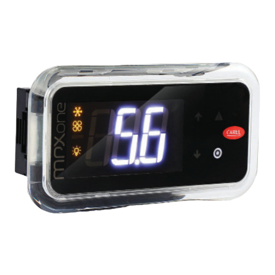
AX3000*小型终端连接到CAREL MPXone控制器时,用作集中商业
制冷应用软件的用户界面,其自带3位数字显示,显示数值范围
是:-999到999。通过NFC界面(近场通信)和BLE(低功耗蓝牙)
实现的无线连接,允许与采用安卓操作系统的移动设备(已安装
了CAREL"APPLICA"应用软件,安卓操作系统可以从Google Play中下
载(如需)此软件)进行交互作用。四键式键盘可允许用户修改
控制器设置。尺寸小、设计简单、与移动设备的可连接性均简化
了现场的参数配置和装置调试。更多信息,请参阅MPXone系统
手册+0300086EN,购买之前,可以在网站www.carel.com上的"文
Model
件"中查阅。
(*)
User terminal, NFC conn., 4
buttons, buzzer
(*)
User terminal, NFC+BLE
conn., 4 buttons, buzzer
(*)
Remote display without
keypad, read-only data
初始操作
用户终端配备了框架,但可以在不影响IP防护等级的情况下轻松
拆除框架。
Model
框架拆卸
框架组装
multiple pack of 10
在面板上安装用户终端
multiple pack of 10
重要事项:仅满足以下条件时,才能保证前端的防护等级为
IP65:
• 矩形孔与平面的最大偏差:≤0.5毫米;
• 配电盘金属板的厚度:0.8-2毫米;
• 安装垫圈的表面最大粗糙度:≤120微米。
注意:用于制作配电盘的金属板(或材料)的厚度必须能够
确保终端安装的安全和牢固。
安装在面板上
30 (1.2)
前端
1.
将配电盘的电缆插入A点(图3);
2.
将电缆穿过电缆接头H;
3.
将控制器放置在开孔中,轻轻按住侧面配件,然后推动前端
直到完全插入为止(侧面接头会弯曲,搭扣会将控制器连接
到面板上)。
30 (1.2)
拆除
从后端打开配电盘(图4):
1.
按住配件,将控制器推出。
显示屏
用户终端
B
图例
1 主域区
C
2 键盘
3 操作模式
图标
图标 功能
2
H
按键
向上
Prg
Always keep the signal cables
and power cable in separate conduits.
Alarm
步骤:在A点(图2)上,按住框架,轻轻向上
推,直到听到"咔哒"一声,然后在B点、C点、D
点上重复上述操作,直至拆下框架。
反向重复拆除框架的操作。
远程显示屏
1
2
1
3
2
图例
主域区
1
操作模式
2
开启
闪烁
电磁阀/压
由计时器启动的压
电磁阀/压缩机启动
缩机
缩机操作
蒸发器风扇
蒸发器风扇启动
-
照明灯
照明灯点亮
-
辅助输出
辅助输出启动
-
时钟
调度机启动
-
Smooth Lines平滑线
节能
-
启动
除霜
除霜启动
等待除霜
维修
维护请求
HACCP 启动
HACCP
-
• 增大/减小该值
• 滚动选择直接访问功能
• LED点亮:滚动选择菜单、参数、直接访问功
向下
能
• LED闪烁:设置参数值
短按该键:
• 保存值,并返回参数代码
• 进入直接访问功能菜单(从主屏幕),并启
用/禁用功能
按住该键(3秒):
• 进入编程模式或返回上一级,但是不保存
• LED点亮:主屏幕/编程模式
• 短按该健:显示屏报警
• 按住该键(3秒):重置报警
• LED点亮/闪烁:确认/启动报警
The AX3000* compact terminals, when connected to a CAREL MPXone
controller, are used as user interfaces for centralized commercial
refrigeration applications. They come with a three-digit display showing
values from -999 to 999. Wireless connectivity via the NFC interface (Near
Field Communication) e BLE (Bluetooth Low Energy), allows interaction
with mobile devices (after having installed the CAREL "APPLICA" app,
available on Google Play (on request) for the Android operating system).
The four-button keypad allows users to modify the controller settings.
Compact dimensions, simple design and connection to mobile devices
all simplify parameter confi guration and unit commissioning in the fi eld.
For further information, see the MPXone system manual +0300086EN,
also available prior to purchase, on the www.carel.com website under
"Documentation".
Preliminary operations
The user terminal is supplied with the frame already fi tted. Nonetheless,
this can be easily removed without aff ecting the IP protection rating.
Removing
Procedure: press the frame gently upwards at point A
the frame
(Fig.2) until hearing a click and repeat the operation at
the other points B, C, D so as to detach the frame
Assembling
Repeat the removal operations in reverse order
the frame
Mounting the terminal on the panel
Important: front IP65 protection is only guaranteed if the following
conditions are met:
• maximum deviation of the drilling rectangle from fl at: ≤ 0.5 mm;
• electrical panel sheet metal thickness: 0.8 - 2 mm;
• maximum roughness of the surface where the gasket is applied:
≤ 120 μm.
Note: the thickness of the sheet metal (or other material) used to make
the electrical panel must be suitable to ensure safe and stable installation of
the terminal.
Mounting on the panel
Front
1.
insert the cable from the electrical panel into point A (Fig.3);
2.
run the cable through the cable gland H;
3.
place the controller in the opening, press lightly on the side tabs and
then on the front until fully inserted (the side tabs will bend, and the
catches will attach the controller to the panel).
Removal
Open the electrical panel and from the rear (Fig.4):
1.
press on the mounting tabs and then push the controller out.
Displays
User terminal
Remote display
1
2
1
3
Key
Key
1 Main fi eld
1
Main fi eld
2 Keypad
2
Operating mode
3 Operating mode
Icons
Icona Function
On
Flashing
Compressor
Solenoid/
Solenoid/compressor
operationforced by
compressor
active
timers
Evaporator fan
Evaporator fan on
-
Lights
Light on
-
Auxiliary output Auxiliary output active -
Clock
Scheduler active
-
Energy saving
Smooth Lines active
-
Defrost
Defrost active
Awaiting defrost
Service
Maintenance request
HACCP
HACCP active
-
Keypad
• Increase/decrease value
• Scroll functions with direct access
• LED on: scroll menu, parameters, direct access
UP
DOWN
functions
• LED fl ashing: modify parameter values
Pressed briefl y:
• save value and return to parameter code
Prg
• enter direct access functions menu (from main
screen) and activate/deactivate functions
Pressed and held (3 s):
• enter programming mode or return to previous
level without saving
• LED on: standard display/programming mode
• Pressed briefl y: display alarms
• Pressed and held (3s): reset alarms
• LED on/fl ashing: acknowledged/active alarm
Alarm
2
Advertisement

Related Manuals for Carel AX3000 Series


Summary of Contents for Carel AX3000 Series
- Page 1 Alarm product, Carel has already completed the checks and tests required by the relevant European directives and harmonised standards, using a typical test setup, which however cannot be considered as representing all possible conditions of the fi nal installatio n.
- Page 2 The lack of such phase of study, which is requested/ 客户须按照与产品有关的文档中所述的方式使用本产品。CAREL的通用合同条款规 indicated in the user manual, can cause the fi nal product to malfunction of which CAREL can S6 +V S1 S3 5V 定了CAREL公司对其产品的责任,该条款可从www.CAREL.com网站和/或与客户达成...
Need help?
Do you have a question about the AX3000 Series and is the answer not in the manual?
Questions and answers