Table of Contents
Advertisement
Quick Links
+0500146IE - rel. 1.1 - 08.06.2022
AX5000*
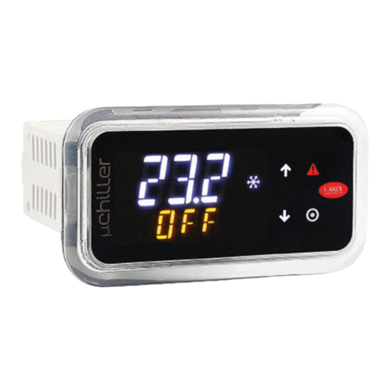
Terminale Utente per μChiller / User terminal for μChiller
Model
Model Type
With NFC
AX
With BTLE
AXB
Dimensioni / Dimensions - mm (in)
con cornice/
46.6
with frame
(1.8)
88.6 (3.5)
senza cornice/
36.5
without frame
(1.4)
78.5 (3.1)
dima di foratura
drilling template
71x29 mm
Fig. 1
Smontaggio della cornice/ Frame dis-assembling
A
D
Fig. 2
Montaggio a pannello/ Panel mounting
1
A
3
Fig. 3
Smontaggio/ Dis-assembling
Fig. 4
ITA
Terminale Utente per μChiller
I terminali AX5000*, sono progettati come interfacce utente per il controllo
CAREL μChiller. Sono dotati di un display a due righe e tastiera con quattro
tasti per fornire all'utente la possibilità di modifi care i parametri di μChiller
in modo facile ed agevole. La gamma off re sempre di serie la connettività
wireless con l'interfaccia NFC (Near Field Communication) e su modelli
dedicati l'interfaccia Bluetooth per interagire con dispositivi mobili
mediante l' A PP Carel "APPLICA" facilitando le operazioni di confi gurazione
dei parametri e di messa in servizio dell'unità in campo. L' A PP APPLICA è
disponibile su Google Play per dispositivi con sistema operativo Android.
Operazioni preliminari (Fig. 2)
Il terminale utente è fornito con la cornice montata. Tuttavia essa può
essere facilmente rimossa senza infl uenzare il grado di protezione IP.
Smontaggio della cornice
Premere delicatamente verso l'alto la cornice nel punto A (Fig.2) fi no a
udire un click e ripetere l'operazione sugli altri punti B, C, D in modo che la
cornice esca dalla sede
Montaggio della cornice
Ripetere le operazioni dello smontaggio nell'ordine inverso
30 (1.2)
Montaggio a Pannello (Fig. 3)
1.
inserire il cavo proveniente dal pannello elettrico nel punto A (Fig.3);
2.
far passare il cavo nel ferma cavo H;
3.
inserire il controllo nell'apertura, premere leggermente sulle alette di
ancoraggio laterali e quindi sul frontalino fi no a fi ne corsa (le alette
di ancoraggio laterali si piegano, i dentini aderiscono e agganciano il
controllo al pannello).
30 (1.2)
Attenzione: il grado di protezione frontale IP65 è garantito solo se
sono soddisfatte le condizioni:
• deviazione massima del rettangolo di foratura dalla superfi cie piana: ≤
0,5 mm;
• spessore della lamiera del quadro elettrico: 0.8 ...2 mm;
• rugosità massima della superfi cie dove è applicata la guarnizione: ≤ 120 μm.
Nota: lo spessore della lamiera (o del materiale) del quadro elettrico
deve essere adeguato per garantire un montaggio sicuro e stabile del
prodotto.
Smontaggio modello a Pannello (Fig. 4)
Aprire il quadro elettrico e dal retro premere sulle alette di ancoraggio e
quindi sul controllo per estrarlo.
B
Attenzione: L'operazione non richiede l'utilizzo di cacciavite o altri
utensili.
Sostituzione: In caso di sostituizione del terminale utente, per evitare
malfunzionamenti:
1.
spegnere (togliere l'alimentazione) l'unità e attendere almeno 1
C
minuto;
2.
sostituire il terminale utente solamente con un terminale nuovo;
3.
riavviare l'unità.
Communicazione Wireless: l'app "Applica" permette di confi gurare il
controllo μChiller da dispositivo mobile (Smartphone, Tablet), tramite
NFC (Near Field Communication) o BLE (Bletooth Low Energy). Procedura
(modifi ca parametri):
1.
scaricare l' A pp CAREL "Applica" per dispositivi Android da Google Play Store;
2.
(nel dispositivo mobile) attivare la comunicazione NFC/Bluetooth e la
connessione dati;
3.
avviare l'app Applica;
2
Tramite NFC (Fig. 5-6)
4a. avvicinare il dispositivo al terminale utente, a una distanza
H
inferiore a 10 mm (per NFC), per eff ettuare il riconoscimento della
confi gurazione
5a. immettere la password richiesta (*);
6a. modifi care i parametri secondo le proprie esigenze;
7a. avvicinare il dispositivo al terminale utente per eff ettuare l'upload
dei parametri di confi gurazione;
Tramite BLE (Bluetooth Low Energy)
4b. premere il tasto "SCANSIONE BLUETOOTH" e selezionare il
dispositivo con cui communicare;
5b. immettere la password richiesta (*);
6b. modifi care i parametri secondo le proprie esigenze.
(*) pre-assegnata dal costruttore dell'unità chiller per permettere la
manutenzione solo al Servizio Assistenza abilitato.
Attenzione: alla prima connessione l'app Applica si allinea alla
versione software del controllo μChiller collegandosi al cloud; pertanto è
necessario, almeno per il primo utilizzo, avere una connessione dati attiva.
Caratteristiche Tecniche
Alimentazione:
Cavo di collegamento al
controllo:
Buzzer:
Sensore di temperatura:
Contenitore
Dimensioni:
Montaggio:
Display:
Condizioni ambientali
funzionamento:
Condizioni ambientali
immagazzinamento:
Connettività NFC:
Connettività BLE:
Grado di protezione:
Grado Inquinamento ambientale: --
Temp. per la prova con la sfera:
Tensione di impulso nominale:
Tipo di azione e disconnessione: 1.Y
ENG
The AX5000* compact terminals are used as user interfaces for CAREL
μChiller control . They come with a two-rows display and four-buttons
Keypad to modify easily and friendly parameters. Wireless connectivity
via the NFC interface (Near Field Communication) e BLE (Bluetooth Low
Energy), allows interaction with mobile devices (after having installed
the CAREL "APPLICA" app; simplify the confi guration of parameters and
commissioning of the unit in the fi eld. CAREL "APPLICA" app is available on
Google Play (on request) for the Android operating system.
Preliminary operations (Fig. 2)
The user terminal is supplied with the frame already fi tted. Nonetheless,
this can be easily removed without aff ecting the IP protection rating.
Removing the frame
press the frame gently upwards at point A (Fig.2) until hearing a click and
repeat the operation at the other points B, C, D so as to detach the frame
Assembling the frame
Repeat the removal operations in reverse order
Mounting the terminal on the panel (Fig. 3)
1.
insert the cable from the electrical panel into point A (Fig.3);
2.
run the cable through the cable gland H;
3.
place the controller in the opening, press lightly on the side tabs and
then on the front until fully inserted (the side tabs will bend, and the
catches will attach the controller to the panel).
Important: front IP65 protection is only guaranteed if the following
conditions are met:
• maximum deviation of the drilling rectangle from fl at: ≤ 0.5 mm;
• electrical panel sheet metal thickness: 0.8 - 2 mm;
• maximum roughness of the surface where the gasket is applied:
≤ 120 μm.
Note: the thickness of the sheet metal (or other material) used to make
the electrical panel must be suitable to ensure safe and stable installation
of the terminal.
Disassembling the panel model (Fig. 4)
Open the electrical panel from the rear and press the anchoring tabs and
then the controller to remove it.
Replacement: if replacing the user terminal, to avoid malfunctions:
1.
switch off (unplug) the unit and wait at least 1 minute;
2.
replace the user terminal only with a new terminal;
3.
restart the unit.
Wireless communication: the "Applica" app can be used to confi gure the
μChiller controller from a mobile device (smartphone, tablet), via NFC
(Near Field Communication) or BLE (Bluetooth Low Energy). Procedure
(modify parameters):
1.
download the CAREL "Applica" app for Android devices from Google
Play Store;
2.
(on the mobile device) enable NFC/Bluetooth communication and
mobile data;
3.
start Applica;
Via NFC (Fig. 5-6)
4a. move the mobile device near to the user terminal, maximum distance
10 mm (for NFC), so as to recognise the
confi guration
5a. enter the password (*);
6a. set the parameters as needed;
7a. move the mobile device near to the user terminal to upload
the confi guration parameters;
Via BLE (Bluetooth Low Energy)
4b. press the "SCAN BLUETOOTH" button and select the device to connect to;
5b. enter the password (*);
6b. set the parameters as needed.
(*) pre-assigned by the chiller manufacturer to allow maintenance only by
authorised service technicians.
Important: during the fi rst connection, Applica aligns itself with the
software version on the μChiller controller via a cloud connection; this
means a mobile data connection is needed at least for this fi rst connection.
Technical specifi cations
Power supply:
13 Vdc ± 10% ottenuta da controllo
ACU; assorbimento 250 mA max.
Alimentazione raccomandata per il
Controller connection
controllo collegato: SELV o PELV
cable
Lunghezza max: 10 m (dispositivo da
Buzzer:
incorporare) Sezione: AWG: 26
Temperature sensor
disponibile in tutti i modelli
Casing
incoporato
Dimensions:
Materia plastica in policarbonato
Mounting:
vedere fi gure
Display:
A pannello
LED 2 righe, punto decimale e icone
Ambient operating conditions:
polifunzionali
Ambient storage conditions:
-20T60 ˚C, <90% U.R. non
NFC:
condensante
-40T85 ˚C, <90% U.R. non
BLE:
condensante
Max distanza 10mm, variabile secondo
Protection index:
il dispositivo mobile utilizzato
Environmental pollution:
Max distanza 10m, variabile secondo
Ball pressure test:
il dispositivo mobile utilizzato
Rated impulse voltage:
IP65 sul frontale, IP20 sul retro
Type of action and
disconnection:
125°C
Construction of the control
0.8 kV
device
Classifi cation according to
protection against electric shock
User terminal for μChiller
Important: The operation does not require the use of a screwdriver
or other tools.
13 Vdc ± 10% supplied by ACU
controller; max current 250 mA.
Power supply recommended for the
connected controller: SELV or PELV
Max length: 10 m (device to be
incorporated) Size: AWG: 26
Available on all models
Built-in
Polycarbonate material
see fi gures
Panel mounting
LED 2 rows, decimal point, and multi-
function icons
-20T60 ˚C, <90% U.R. non-condensing
-40T85 ˚C, <90% U.R. non-condensing
Max distance 10 mm, variable
according to the mobile device used
Max distance 10 mm, variable
according to the mobile device used
P65 at front, IP20 at rear
3
125°C
0.8 kV
1.Y
Device to be incorporated
To be incorporated in class 1 or 2
appliances
Advertisement
Table of Contents

Related Manuals for Carel AX5000


Summary of Contents for Carel AX5000
- Page 1 I terminali AX5000*, sono progettati come interfacce utente per il controllo The AX5000* compact terminals are used as user interfaces for CAREL CAREL μChiller. Sono dotati di un display a due righe e tastiera con quattro μChiller control . They come with a two-rows display and four-buttons tasti per fornire all’utente la possibilità...
- Page 2 The lack of such phase of study, which is requested/indicated in the user manual, can cause the fi nal product to malfunction of which CAREL can not be held responsible. The fi nal client must use the product only in the Pressione breve: Conferma il valore del parametro in manner described in the documentation related to the product itself.
Need help?
Do you have a question about the AX5000 and is the answer not in the manual?
Questions and answers