Table of Contents
Advertisement
Quick Links
+05C001895 - rel. 1.4 - 02.03.2020
pGDx
pGDx Touch 4.3" - User terminal pGDx Touch 4.3"
(mm) / Dimensions (mm)
31,6
116,6
WRONG
133,8
RIGHT
4
151,5
33,1
8,9
(
3d) -
PGTA00SM40
Accessory for wall surface installation (ref. Figure 3d) - P/N: PGTA00SM40
31,9
151,7
23
133,8
(
3c) -
PGTA00RM40
Accessory for fl ush-mounted wall installation (ref. Figure 3c) - P/N: PGTA00RM40
150,8
63,1
133,8
54,2
to remove for plasterboard installation
Fig. 1
(mm) / Assembly and installation (mm)
/ Frontal
Frame code:
PGTA**F[B,W][0,1]*
Tightening torque 0.4 Nm
Fig.3a
/ Back
Important:
keep the fl at cable
isolated from the
metal panel
Carel
Not supplied by Carel
Fig.3b
Wall mounting
Note:
Do not run power
cables inside the
fl ush-mount box
Frame code:
PGTA**F[T,H][0,1]*
Fig.3c
Wall surface
Note:
can only be used
PG*******[B,E,W,H]***
with models
PG*******[B,E,W,H]***
Frame code:
Fig.3d
PGTA**F[T,H][0,1]*
pGDx 4.3
RS485
PGR04****A***
PGR04****B***
PGR04****C***
PGR04****R***
PGR04****W***
PG[B,R]04****E***
134
PG[B,R]04****H***
Ø 4
dima di foratura
drilling template
pGDx
127x69 mm
Wi-Fi
PGTA00TRX0
133,8
125,7
83,5
RIGHT side connection STANDARD 503
57,3
RIGHT side connection CHI/DE STANDARD
–
–
–
57,3
LEFT side connection CHI/DE STANDARD
83,5
LEFT side connection (Ethernet version) STANDARD 503
RP-SMA
148,3
to remove for plasterboard installation
c.touch
HMI
c.touch
(.ZIP fi le)
pGDx
0.4 Nm
"Update...")
(
pGDx
)
Flat cable passage
(only in case
settings"
of external keypad)
/ Wall box
standard ITA/CHN/DEU/USA
65K
ETH
RJ12
Wi-Fi
-
-
-
1
1
-
-
-
1
1
-
-
1
1
-
1
-
-
-
1
-
-
-
1
-
RS485
PG*04***D[H,R,W ]***
Ethernet RS485
WiFi
(500 Vac
IEC 60730-1)
IP65
0 4 Nm
boot
"Update package" )
USB
USB
pGDx
USB
"Show system
c.touch
pGDx
BSP
pGDx
IP
(
DHCP DNS)
WiFi
Modbus
pGDx
...
pGDx BSP
(Confi gOS, MainOS, Bootloader
...)
Introduction
pCO sistema
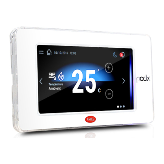
The pGDx 4.3 inch graphic terminal is part of the family of touchscreen terminals designed
to simplify user interface with the pCO sistema family controllers. The electronic technology
used and the new 65K colour display means high quality images and advanced functions
are available for a superior appearance. The touchscreen panel moreover makes interaction
between the user and the unit much easier by simplifying navigation between the various
screens. Diff erent types of installation are available, depending on the model: front or
back panel, wall surface or fl ush-mount. In any case, the device can be mounted either
horizontally or vertically.
Part numbers
-
No. RS485
No. ETH
Codice
1
ports
ports
1
PGR04****A***
-
1
PGR04****B***
1
1
PGR04****C***
1
1
PGR04****R***
1
1
PGR04****W***
1
PG[B,R]04****E***
-
PG[B,R]04****H***
-
Packaging contents
pGDx; power supply and RS485 connectors (only on models where featured); fastening
screws; technical leafl et, Wi-Fi antenna (only for models where fi tted, PG*04***D[H,R,W]***).
Not included: frame, PGTA00TRX0 power supply and wall mounting boxes .
Installation warnings
For correct installation contact a qualifi ed installer.
Do not install the terminals in environments with the following characteristics:
• relative humidity greater than the value specifi ed in the technical specifi cations;
• strong vibrations or knocks;
• exposure to aggressive and polluting atmospheres (e.g.: sulphur and ammonia fumes,
salt spray, smoke) so as to avoid corrosion and/or oxidation;
• strong magnetic and/or radio frequency interference (therefore avoid installing the units
near transmitting antennae);
• exposure to direct sunlight or the elements in general;
• large and rapid fl uctuations in the room temperature;
• environments where explosives or mixes of fl ammable gases are present.
The following requirements shall be met:
• with built-in temperature/humidity sensor, it is recommended to:
– only use faceplates fi tted ventilation openings
– install the display away from air streams coming from heating/cooling systems
– if installed vertically, position the probe at the bottom of the display
• only use shielded cables for Ethernet and RS485 communication networks;
• power supply voltages other than those specifi ed may seriously damage the system;
• use cable ends suitable for the corresponding terminals. Loosen each screw and insert the
cable ends, then tighten the screws. When the operation is completed, slightly tug the cables
to check they are suffi ciently tight;
• in models with an external WiFi antenna, ensure at least basic insulation (500 Vac
according to IEC 60730-1) between the RP-SMA connector and the protective earth;
• do not open the product when powered;
• operation at low temperatures may cause a noticeable decline in the response speed of the
display. This should be considered normal and does not indicate a malfunction.
• for one correct installation of IP65 models be safe of a 0,4 Nm screws tightening and a
correct assembly of the gasket.
• avoid any contact of the product with live parts.
• be sure that cables are accurately fi xed in order to avoid contact with live parts in case of
their accidentally disconnection.
Meaning of the colours on the notifi cation bar
At power-on, the notifi cation bar briefl y shows a blue signal to indicate the start of the
boot phase. The subsequent signals are then managed by the application program
developed using c.touch.
HMI Runtime and/or application update
1. Copy the update package (.ZIP fi le) containing the runtime
or application, or both, depending on the options selected
when generating the "Update package" using c.touch, to a
USB pendrive and then plug the pendrive into the pGDx and
hold the pGDx terminal screen for a few seconds until the
shortcut menu is displayed, disableable application side (see
the fi gure on the side):
2. Select "Update..." to
start the Runtime and/
or application update
procedure. The update
utility will start and the
following window will
be displayed:
System settings
Touch and hold the pGDx terminal screen
for a few seconds until the shortcut
menu is displayed (see the fi gure below).
Select "Show system settings"; the main
confi guration program screen will be
displayed (fi gure on the side):
Below is a list of the functions relating to the diff erent menu items:
Language
Set the system language (not the c.touch application)
Contains information on the pGDx: BSP version, Memory, Timers
System
and temperature / humidity sensor (if featured)
Logs
Download the system log fi les
Date & Time
Set pGDx date and time using the automatic or manual procedure
Show current system IP data (address, subnet, Gateway, DHCP, DNS)
Network
and access the Ethernet and WiFi interface
Start/stop various system services (Modbus server port, pGDx
Services
network address,...)
Update the diff erent pGDx BSP partitions (Confi gOS, MainOS,
Management
Bootloader, Splash image, etc....)
Set brightness, backlight timeout, screen orientation and touch
Display
panel calibration
Restart
Restart the system
Authentication
Set the password used to access
EXIT
Exit the menu
Wi-Fi
No. RJ12
Power supply
connectivity
ports
port
-
-
1
-
-
-
-
1
1
-
-
1
1
-
1
-
-
1
1
-
-
1
1
-
1
3. Then follow the
guided procedure,
selecting the fi le
saved on the USB
pen drive and
clicking the next
button to confi rm.
Advertisement
Table of Contents

Related Manuals for Carel pGDx Touch 4.3


Summary of Contents for Carel pGDx Touch 4.3
- Page 1 +05C001895 - rel. 1.4 - 02.03.2020 pGDx pGDx Touch 4.3” - User terminal pGDx Touch 4.3” Introduction pGDx 4.3 pCO sistema The pGDx 4.3 inch graphic terminal is part of the family of touchscreen terminals designed to simplify user interface with the pCO sistema family controllers. The electronic technology used and the new 65K colour display means high quality images and advanced functions are available for a superior appearance.
- Page 2 正式授权的系统中造成干扰。 can cause the fi nal product to malfunction of which CAREL can not be held responsible. The fi nal client must use the interference in duly authorized systems. product only in the manner described in the documentation related to the product itself. The liability of CAREL in relation...
Need help?
Do you have a question about the pGDx Touch 4.3 and is the answer not in the manual?
Questions and answers