Advertisement
Quick Links
+05C001475 - rel. 1.3 - 01/06/2012
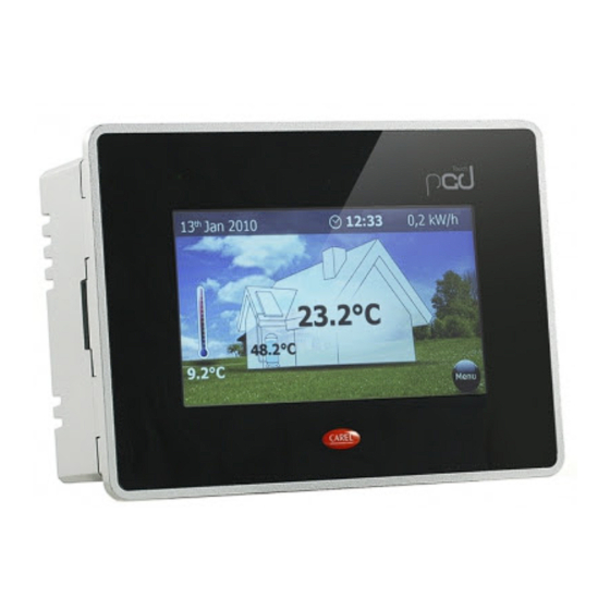
pGD touch
触摸式用户手操器 pGD Touch 4.3" - User terminal pGD Touch 4.3"
触摸式用户手操器 / Assembly and installation
尺寸与开孔模板 / Dimensions and drilling template (in mm/inc.)
55.80
147
Fig.1
H mm (inc)
尺寸 / Dimensions
107 (4.2)
开孔 / Drilling template
96 (3.8)
比例2:1
Note: flat side of the gasket facing the terminal
注意: 平整一面的垫圈朝向手操器
Fig.2
Fig.3
注意: 调节每个固定螺丝直到框角与面板接上。 / Screw each fixing screw until the
bezel corner gets in contact with the panel.
PGDT 可以安装在最大厚度为6mm的面板上 / PGDT could be mounted on pannels with
a maximum thickness of 6mm.
电池更换 / Battery replacement:
To access the battery for replacement or disposal, power down the device
and remove the rear cover (remove the 4 screws on the corners). Use model
BR2330 lithium batteries (non-rechargeable)./ 要更换或处理电池,关闭设
备电源,拆下后盖(拆下角上的4个螺丝)。使用型号为 BR2330 的锂
电池(不可重复充电的)。
注意!如果使用不正确的电池,会有爆炸的危险。 / Warning! danger
of explosion if an incorrect battery is used.
Ethernet 网络 (仅适用于 PGDT04000F02*) / Ethernet network
(PGDT04000F02* only)
这两个Ethernet端口都是连接到一个内部交换器上,用于终端管理Ethernet网
络上的通讯。因此,无须外部的交换器,即可创建一个由几个设备组成的网
络。这个交换器具有Auto–MDIX(自动转线路),说明这种网络可以使用常规
的软线创建,无需交叉线连接两台设备(NIC)。
必须指出的是当终端未上电时从门户1到2的通讯是中断的,反之亦然。
对于Ethernet连接,使用CAT-5 STP屏蔽线。
The two Ethernet ports are connected to an internal hub-switch that manages the
Ethernet traffic transiting over the network for the terminal. Consequently, a network
of several devices can be created without requiring an external hub. The switch
features Auto–MDIX (auto crossover), meaning the network can be created using
normal patch cables, without needing crossover cables to connect two devices (NIC).
It must be remembered that when the terminal is not powered, traffic from door 1 to
2 and vice-versa is interrupted.
For the Ethernet connections use CAT-5 STP shielded cables.
Meaning of LED on RJ45 connector /
Green -
RJ45 连接器上的LED的含义
Link/Act
产品简介
pGD Touch 4.3寸图形化终端是触摸式终端系列产品中的一个组成部分,专为
简化与pCO sistema的用户操作而设计。
本产品所采用的电子技术和新型的65K色彩显示意味着高分辨率的图像和先进
的功能,可达到更为出众的显示效果。通过简化不同界面之间的导航,触摸
式的面板使用户与机组之间的互动更加简单。
型号代码
代码
PGDT04000FS00
PGDT04000F020
包装内容
• pGD Touch;
• 电源和RS485连接头;
• 带螺丝的紧固支架组件;
• 说明书;
+0,50
136 - 0,50
安装注意事项
为了确保正确安装,请联络有资质的安装商。
请不要将产品安装在具有下列特征的环境中:
• 相对湿度大于产品技术规格中的标定值;
W mm (inc)
P mm (inc)
• 强振动或碰撞;
147 (5.8)
55.8 (2.2)
136 (5.3)
• 暴露在侵袭性和污染的大气中(例如硫磺和氨气,含盐的雾,烟尘);
Tab. 1
• 强磁的和/或无线电频率干扰(因此避免将产品安装在发送天线近处);
• 暴露在阳光直射处;
• 室温变动大且快速;
• 存在爆炸物或混合了易燃气体的环境;
以下注意事项必须遵守:
• 对于Ethernet和RS485通讯网络仅使用屏蔽线;
• 不能使用非标定的电压,否则可能会严重损坏系统;
• 使用适用于相应接线端的线缆末端。松开每个螺丝,将线缆末端插入,然
后紧固螺丝。完成后,轻轻地拉动线缆,检查它们是否是十分固定;
• 在电源开启时不要打开产品;
• 在低温下操作可能导致显示屏的响应速度明显放慢。这必须被视为正常而
不是表示一个故障。
A
前面板上LED灯的含义
PGDT04000FS0
绿色/Green
开机
红色/Red
不存在
HMI和/或程序更新
将包含了Runtime或程序或两个都包含的更新包(.ZIP文件)复
制到一个USB驱动器上,取决于当使用1Tool-TE生成"更新包"
package")时所选择的选项,然后将驱动器插到
("Update
pGDTouch上。触摸并按住pGD Touch终端的屏幕持续几秒钟
直到显示快捷菜单。
选
择
更
( "Update...") 启
动 Runtime或 者 程
序更新。更新进程
将开始并且将显示
下列窗口。
系统设定
触摸pGD Touch
终端的屏幕持续
几秒钟直到显示
快捷菜单:
按上一步和下一步按钮循环滚动不同的功能,当所需功能以浅蓝色突出显示
时,按下选择,运行这个功能。
功能名称
Fig. 4
校准触摸屏
显示设定
时间
BSP 设定
网络
设定设备地址
Yellow - On/O =
100MBps/10MBps
Fig. 5
技术规格
显示
类型
分辨率
有效显示区
色彩
说明
分辨率
1个485端口
480 x272
1个USB端口
1个光电隔离485端口
480 x272
1个host2.0 USB端口
2个Ethernet端口
1个SD卡连接口
1个可选择键盘连接口
PGDT04000F02
上电
如果闪烁,表明设备通讯是启用的
开启,当系统启动时
如果是稳定不动的,表示时间设定已经丢
失因为电池没电了
选 择 " 自 动 选
新
择 最 匹 配 的 "
"Auto select best
match"然 后 按
下 下 一 步 以 启
动更新程序。
待程序结束后,按下关闭"Close"。
选择"显示系统
设定",将出现
主设置程序
界面将出现(如右图)
说明
重新校准触摸屏。按照下面的指导说明使用一根触摸笔精确地
按下十字标。
访问系统菜单以设定背光自动终止时间和调节亮度。
默认值 = 5' 。自动关闭,无需被禁用
用于设定系统时钟和时区(始终设定为GMT)
版本:显示操作系统版本
定时器:显示系统运行时间和背光时间
蜂鸣器:蜂鸣器响,当触摸触摸屏时
显 示 当 前 系 统 I P 数 据 (
如 下 图 ) ( 地 址 , 子 网 ,
网 关 , D H C P , D N S ) 和
Ethernet端口设置菜单
设定通讯协议需要的设备
地址 (Modbus RTU Server,
Bacnet)。只能为正在运行
的协议改变地址。选择
通讯端口(Ethernet, Com1,
Com2),使用上方的箭头。
RC
确保协议正是您所需要的。使用数字键盘输入地址,地址须在
最小值和最大值之间。按键
删除最后一位数字,Clear 按键删
除所有数字。默认值是1ToolTE编辑器指定的。 Cancel按键取消变
更, OK按键使变更生效,如果输入的值是有效地的,否则将显
示一个错误信息。
LCD TFT
480x272 宽
对角4.3"
64 K
Introduction
The pGD Touch 4.3 inch graphic terminal is part of the family of touchscreen terminals
designed to simplify user interface with the pCO sistema family controllers.
The electronic technology used and the new 65K colour display means high
quality images and advanced functions are available for a superior appearance. The
touchscreen panel makes interaction between the user and the unit much easier by
simplifying navigation between the various screens.
Model codes
Code
Description
PGDT04000FS00
1 485 port
1 USB port
PGDT04000F020
1 optically-isolated 485 port
1 Host 2.0 USB port
2 Ethernet ports
1 SD card connector
1 optional keypad connector
Packaging contents
• pGD Touch;
• power supply and RS485 connectors;
• fastening bracket kit with screws;
• instruction sheet.
Installation warnings
For correct installation contact a qualified installer.
Do not install graphic terminal in environments with the following characteristics:
• relative humidity greater than the value specified in the technical specifications;
• strong vibrations or knocks;
• exposure to aggressive and polluting atmospheres (e.g.: sulphur and ammonia
fumes, saline mist, smoke) so as to avoid corrosion and/or oxidation;
• strong magnetic and/or radio frequency interference (therefore avoid installing
the units near transmitting antennae);
• exposure to direct sunlight or the elements in general;
• large and rapid fluctuations in the room temperature;
• environments where explosives or mixes of flammable gases are present;
The following warnings must be observed:
• only use shielded cables for Ethernet and RS485 communication networks;
• power supply voltages other than those specified may seriously damage the system;
• use cable ends suitable for the corresponding terminals. Loosen each screw and insert
the cable ends, then tighten the screws. When finished, slightly tug the cables to check
they are sufficiently tight;
• do not open the product when powered;
• operation at low temperatures may cause a visible decline in the response speed of the
display. This should be considered normal and does not indicate a malfunction.
Meaning of the LED on the front panel
PGDT04000FS0
PGDT04000F02
Green
Power on
Power on
If blinking reports device communication active
Red
Not present
On during system start-up
If on steady indicates time setting has been lost
due to battery discharge
HMI Runtime and/or application update
Copy the update package (.ZIP file) containing the runtime or
application, or both, depending on the options selected when
generating the "Update package" using 1Tool-TE, to a USB pendrive
and then plug the pendrive into the pGD Touch. Touch and hold
the pGD Touch terminal screen for a few seconds until the shortcut
menu is displayed:
Select "Update... " to
Select "Auto
start the Runtime
select best
and/or application
match" and
update procedure
press next;
The update utility
this starts
will start and the
the update
procedure. Wait for the procedure to finish
following window
and press "Close".
appears:
System settings
Hold your finger
Select "Show
on the pGDTouch
system
terminal for a few
settings";
seconds until the
the main
menu is displayed:
configuration
program
screen will appear (following figure).
The Next and Back buttons scroll the various functions cyclically; when the required
function is highlighted in light blue, pressing the selection runs the function.
Function
Description
name
Calibrate
Recalibrates the touch screen. Use a stylus and carefully press the crosses
touch
following the proposed indications.
Display
Access the system menu to set the backlight auto shut off time and adjust the
settings
brightness. Default = 5' . Auto shut off does not need to be disabled
Time
Allows the adjustment of the system clock and time zone (always set at GMT)
BSP
Version: Shows the operating system version
Settings
Timers: shows the hours of operation of the system and the backlight
Buzzer: allows you to activate the buzzer sound when touching the touch
screen
Network Shows the current IP data of the
system (see following fig.) (address,
subnet, Gateway, DHCP, DNS) and
allows access to the ethernet port
configuration menu
Set
Setting the device address for
device
protocols that require it (Modbus
address
RTU Server, Bacnet). The address
can only be changed for protocols
that are running. Select the
communication port (Ethernet,
Com1, Com2) using the arrow keys
at the top.
Make sure the protocol is the one you want. Use the numeric keypad to insert
the address, within the minimum and maximum values. The key
the last number, the Clear key removes all the numbers. The default value is
assigned through 1ToolTE editor. The Cancel key cancels the change, the OK
key makes the change effective if the value entered is valid, otherwise an error
message is displayed.
Technical specifications
Display
Type
LCD TFT
Resolution
480x272 Wide
Active display area
4.3" diagonal
Colours
64 K
Resolution
480 x272
480 x272
removes
Advertisement

Related Manuals for Carel pGD touch PGDT04000FS00


Summary of Contents for Carel pGD touch PGDT04000FS00
- Page 1 +05C001475 - rel. 1.3 - 01/06/2012 pGD touch 触摸式用户手操器 pGD Touch 4.3” - User terminal pGD Touch 4.3” Introduction 产品简介 The pGD Touch 4.3 inch graphic terminal is part of the family of touchscreen terminals pGD Touch 4.3寸图形化终端是触摸式终端系列产品中的一个组成部分,专为 designed to simplify user interface with the pCO sistema family controllers. 简化与pCO sistema的用户操作而设计。...
- Page 2 CAREL can not be held responsible. The final client must use the product signal cables from the cables carrying inductive loads and power cables to avoid (to size the device see the rated data shown under “Ratings”...
Need help?
Do you have a question about the pGD touch PGDT04000FS00 and is the answer not in the manual?
Questions and answers