Table of Contents
Advertisement
Quick Links
+050000135 - rel. 1.1 - 19.09.2007
IR*U* e IR*X*
- Terminali e visualizzatori a led / LED terminals and displays
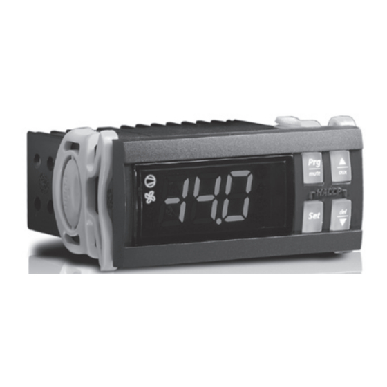
IR*U* (con tasti) / IR*U* (with buttons)
IR*X* (senza tasti) / IR*X* (no buttons)
Connessioni elettriche IR*U* e IR*X* (vista posteriore)
IR*U* and IR*X* electrical wiring (back wiew)
A
Power Supply
GND
Rx/Tx
GND
0 T 5 0
1 2 3
26
GND
MPXPRO
T.U.I.
24
Scheda base
Tx/Rx
Main Board
25
VL
Montaggio a pannello IR*U* e IR*X* (visione laterale)
IR*U* and IR*X* panel mounting (side view)
B
Rimozione terminali IR*U* e IR*X* (visione laterale)
Removing the IR*U* and IR*X* terminals (side view)
D
Porta commissioning / Commissioning port
A
B
C
Caratteristiche generali
I terminali IR* U* e IR* X* (Fig. 1) collegati ad un controllo CAREL visualizzano la
temperatura trasmessa dal controllo e ne registrano eventuali anomalie di funzionamento.
Nei modelli provvisti di tasti (IR* U*) il terminale è anche in grado di impostare i valori
trasmessi dal controllo.
Cavo di collegamento
Il cavo per collegare IR*U* o IR*X* ad un controllo CAREL non è incluso; è necessario
munirsi di un cavo con le seguenti caratteristiche:
- a 3 conduttori;
- con una distanza massima di 10 mt tra il controllo e il terminale;
- sezione di 0,5...2,5 mm
Fig. 1
Installazione e collegamenti (Fig. 2)
- Eseguire tutti i collegamenti elettrici necessari
(consultare il manuale d'uso del controllo per maggiori informazioni sui collegamenti);
- Inserire il terminale nel foro del pannello
verso altre interfacce utente
- Applicare le 2 staffette laterali facendole scorrere sui binari laterali del terminare
to other user interfaces
(PSTCON0%B0)
Per rimuovere il terminale, premere ed estrarre le 2 staffette laterali, estrarre il terminale
dal pannello ed infine togliere i collegamenti elettrici. Per l'estrazione delle staffette
premere come indicato da figura
Porta commissioning (Fig. 3)
I terminali IR* U* e IR* X* sono dotati di porta commissioning che permette il
collegamento tra un PC ed un controllo MPX PRO.
Per individuare tale porta nel terminale è necessario:
• Rimuovere la placchetta del terminale/visualizzatore inserendo un cacciavite a lama
piatta nell'apertura in basso a sinistra della placchetta
C
• Rimuovere la gomma della pulsantiera
• Collegare il cavo tLAN, in dotazione con il convertitore USB-tLAN (IROPZTLN00)
Consultare il manuale d'uso di MPX PRO per un corretto collegamento ed utilizzo della
porta commissioning.
Caratteristiche tecniche (Fig. 4)
Alimentazione
Contenitore
Montaggio
Fig. 2
Display
Temperatura di
cavo tLAN / tLAN cable
funzionamento
Umidità di
funzionamento
Temperatura di
immagazzinamento
Umidità di
immagazzinamento
Grado di protezione
Fig. 3
frontale
2
.
A
A
A
estraendo i cavi dal foro del pannello
B
B
;
B
C
C
C
D
.
D
D
A
A
;
B
;
B
C
C
D
Tensione 10...15 V ottenuta dal controllo collegato;
D
assorbimento 60 mA max.;
si raccomanda che l'alimentazione utilizzata per il controllo collegato
sia di tipo SELV (tipo di alimentazione con isolante galvanico di
grado rinforzato).
Materia plastica;
dimensioni 35x76.4x39.4 mm;
profondità incasso 31mm.
A pannello liscio, rigido ed indeformabile e mediante staffe di
fissaggio laterali, da pressare fino a fine corsa;
dima di foratura dimensioni 28.8±0.2 x 70.8±0.2 mm.
3 cifre digit LED, con punto decimale sulla seconda cifra;
visualizzazione –99...999;
stati di funzionamento indicati con 10 icone grafiche sul display.
0T50 °C
<90% U.R. non condensante
-20T70 °C
<90% U.R. non condensante
IP65 (montaggio su pannello liscio ed indeformabile con
guarnizione)
General features
IThe IR* U* and IR* X* terminals (Fig. 1) connected to a CAREL controller display the
temperature transmitted by the controller and record any operating anomalies. In the
Models with buttons (IR* U*), the terminal can also be used to set the values transmitted
by the controller.
Connection cable
The cable used to connect IR*U* or IR*X* to a CAREL controller is not included; use a
cable with the following characteristics:
- 3 wires;
- maximum distance 10 m between the controller and the terminal;
- cross-section of 0.5 to 2.5 mm
2
.
A
Installation and connections (Fig. 2)
- EMake all the electrical connections required
A
B
opening on the panel (see the controller user manual for further information on the
connections);
B
- Insert the terminal in the opening on the panel
C
;
- Apply the 2 side brackets, sliding them on the side rail of the end
C
To remove the terminal, press and remove the 2 side brackets, remove the terminal from
D
the panel and finally remove the electrical connections. To remove the brackets, press as
shown in the figure
D
.
Commissioning port (Fig. 3)
The IR* U* and IR* X* terminals come with a commissioning port, which is used for
A
connection between a PC and an MPX PRO controller.
To identify this port on the terminal, proceed as follows:
A
B
• Remove the frame from the terminal/display by inserting a flat-head screwdriver in
the opening on the bottom left of the frame
• Remove the rubber from the keypad
B
C
.
• Connect the tLAN cable, supplied with the USB-tLAN converter (IROPZTLN00)
Refer to the MPX PRO user manual for the correct connection and use of the commissio-
C
D
ning port.
Technical specifications (Fig. 4)
D
Power supply
Voltage 10 to 15 V from the controller connected;max. current
input 60 mA;
the power supply to the controller connected should be SELV
(power supply with reinforced insulation).
Case
Plastic;
dimensions 35x76.4x39.4 mm;
mounting depth 31mm.
Assembly
Smooth, hard and indeformable panel using side fastening
brackets, pressed in fully;
drilling template dimensions 28.8±0.2 x 70.8±0.2 mm.
Display
3 LED digits, with decimal point on the second digit;
display –99 to 999;
operating status indicated by 10 graphic icons on the display.
Operating
0T50 °C
temperature
Operating humidity <90% RH non-condensing
Storage
-20T70 °C
temperature
Storage humidity
<90% RH non-condensing
RH non-condensing
Front panel index of
IP65 (assembly on smooth and indeformable panel with gasket)
protection
A
A
by removing the cables from the
A
B
B
B
;
C
;
C
C
D
D
D
A
B
A
;
;
C
.
B
D
C
D
Advertisement
Table of Contents

Related Manuals for Carel IR U Series


Summary of Contents for Carel IR U Series
- Page 1 Il cavo per collegare IR*U* o IR*X* ad un controllo CAREL non è incluso; è necessario The cable used to connect IR*U* or IR*X* to a CAREL controller is not included; use a munirsi di un cavo con le seguenti caratteristiche: cable with the following characteristics: - a 3 conduttori;...
- Page 2 COLOUR: X terminale solo visualizzatore Colori display: R= rosso The liability of CAREL in relation to its products is specified in the CAREL general contract X terminal with display only Display colours: R= red U terminale con visualizzatore e comando a 4 tasti conditions, available on the website www.carel.com and/or by specific agreements with...
Need help?
Do you have a question about the IR U Series and is the answer not in the manual?
Questions and answers