
Related Manuals for Carrier AquaSnap 30RB 017


Summary of Contents for Carrier AquaSnap 30RB 017
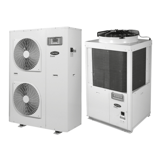
- Page 1 I N S TA L L AT I O N , O P E R AT I O N A N D M A I N T E N A N C E I N S T R U C T I O N S Air-cooled liquid chillers and reversible cycle air-water heat pump with integrated hydraulic module...
-
Page 2: Table Of Contents
CONTENTS PHYSICAL DATA AND ELECTRICAL DATA ............................. 4 Model 30RB ......................................4 Model 30RQ ......................................5 DIMENSIONS AND LOCATION OF HYDRAULIC CONNECTIONS (MM) ..................6 Mod. 30RB/30RQ 017-021 .................................. 6 Mod. 30RB/30RQ 026-040 .................................. 7 USER INTERFACE AND MAIN SWITCH ............................7 CLEARANCES (MM) .................................. - Page 3 AIR-COOLED LIQUID CHILLERS AND REVERSIBLE AIR-TO-WATER HEAT PUMPS WITH INTEGRATED HYDRONIC MODULE For the use of the control system, refer to the Pro-Dialog+ control manual.
-
Page 4: Physical Data And Electrical Data
1 - PHYSICAL DATA AND ELECTRICAL DATA 1.1 - Model 30RB Table I: Physical data 30RB 026-A 033-A 040-A Operating weight With hydraulic module Refrigerant charge R-410A Compressor One scroll compressor Evaporator One plate heat exchanger Net water volume 1,52 1,71 2,28 Water connections (MPT gas) -
Page 5: Model 30Rq
1 - PHYSICAL DATA AND ELECTRICAL DATA 1.2 - Model 30RQ Table I: Physical data 30RQ 026-A 033-A 040-A Operating weight With hydraulic module Without hydraulic module Refrigerant charge R-410A Compressor One scroll compressor Evaporator One plate heat exchanger Net water volume 1,52 2,28 2,85... -
Page 6: Dimensions And Location Of Hydraulic Connections (Mm)
2 - DIMENSIONS AND LOCATION OF HYDRAULIC CONNECTIONS (MM) 2.1 - Mod. 30RB/30RQ 017-021 1135 (Fixing holes ø 10) Water inlet Water outlet Fill kit connection Relief valve outlet Electrical connections... -
Page 7: Mod. 30Rb/30Rq 026-040
2 - DIMENSIONS AND LOCATION OF HYDRAULIC CONNECTIONS (MM) 2.2 - Mod. 30RB/30RQ 026-040 (Fixing holes ø 10) 710 (Fixing holes ø 10) 1002 Water inlet Water outlet Automatic fill kit connection (optional) Electrical connections 3 - USER INTERFACE AND MAIN SWITCH Service door User interface Disconnector... -
Page 8: Clearances (Mm)
4 - CLEARANCES (MM) 4.1 - For horizontal outlet unit (30RB-30RQ 017-021) 200 mm 700 mm 200 mm 300 mm 700 mm 200 mm 400 mm 300 mm 200 mm 400 mm 400 mm 400 mm 500 mm 1000 mm 1000 mm 4.2 - For vertical outlet unit (30RB-30RQ 026-040) 500 mm... -
Page 9: General Information And Hydraulic Module
15 l of condensate. under conditions other than those indicated in Tables “Operating On demand, Carrier may supply an optional condensate drain pan limits”, will immediately void the unit warranty. to be placed under the unit. The corresponding codes are ■... - Page 10 5 - GENERAL INFORMATION AND HYDRAULIC MODULE Siting the unit Check that: ■ The location is able to support unit operating weight (Table I). ■ There is sufficient space for servicing and air flow around the unit (see “Clearances”figure). ■ The selected site is without dust or foreign material which could obstruct the coil. ■...
-
Page 11: Hydraulic Module
5 - GENERAL INFORMATION AND HYDRAULIC MODULE 5.2 - Hydraulic module The hydraulic module is factory-installed. This eliminates the need to install the necessary components on-site, making the unit more compact and easy to install. 5.2.1 - Hydraulic module for 30RB/30RQ 017-021 unit Automatic purge Drain valve Pump... -
Page 12: Water Connections
6 - WATER CONNECTIONS Typical diagram of hydraulic circuit with hydraulic module 17-21kw R S V Typical diagram of hydraulic circuit with hydraulic module 26-40kw R S V Hydraulic module (units with hydraulic module) - - - Water supply automatic system (optional) Legend Hydraulic components System components... - Page 13 2. It is advisable to install shut-off valves to allow isolation of the most important circuit components, as well as the heat Carrier recommendations on heat exchange fluids: exchanger itself. These valves (ball, globe or butterfly valves) should produce ■...
-
Page 14: Outlet Available Static Pressure Of The Unit With Hydraulic Module
6 - WATER CONNECTIONS 6.1 - Outlet available static pressure of the unit with hydraulic module Data applicable for: ■ Fresh water 20°C ■ In case of use of the glycol, the maximum water flow is reduced. Water flow rate, l/s Legend 30RB-RQ 017 30RB-RQ 021... -
Page 15: Electrical Connections And Refrigerant Charge
CAUTION: atmosphere during installation, maintenance or equipment disposal. Operation of the unit on improper line voltage constitutes abuse and is not covered by the Carrier warranty. 3. The deliberate gas release into the atmosphere is not allowed. IMPORTANT: 4. If a refrigerant leak is detected, ensure that it is stopped To ensure the correct unit power supply (cable entry, and repaired as quickly as possible. -
Page 16: Refrigerant Charge And Electronic Control
7 - ELECTRICAL CONNECTIONS AND REFRIGERANT CHARGE 8. A logbook must be established for equipments subject to Checking the charge periodic leak tests. It should contain the quantity and the CAUTION: type of fluid present within the installation (added and Accidental exhaust of refrigerant, whether due to a small leak recovered), the quantity of recycled fluid, regenerated or or to a large discharge from a piping rupture, can cause... -
Page 17: Electronic Control
8 - REFRIGERANT CHARGE AND ELECTRONIC CONTROL A powerful control system CAUTION: If brazing is to be done, the refrigerant circuit must be filled The PID control algorithm with permanent compensation for the with nitrogen. difference between entering and leaving water temperature and Combustion of refrigerant produces toxic phosgene gas. -
Page 18: Start-Up, Compressor Replacement
9 - START-UP, COMPRESSOR REPLACEMENT 9.1 - Start-up 9.2 - Compressor replacement Unit start-up is done by the electronic control described above, As the compressors are hermetic, when an internal fault occurs, and must always be carried out under the supervision of a qualified the compressor must be replaced. -
Page 19: Pump Replacement, Unit Protection Devices
Air entering temperature °C External relief valve (1) Contact Carrier if an entering water temperature lower than 7.8°C is necessary. (2) For low-temperature applications, where the leaving water temperature is below (1) Classified for protection in normal service situations. 5°C, a frost protection solution must be used. -
Page 20: Operating Limits 30Rq
Plate heat exchanger °C We recommend consulting the factory for these particular (1) Contact Carrier if an entering water temperature lower than 7.8°C is necessary. applications. (2) For low-temperature applications, where the leaving water temperature is below 5°C, a frost protection solution must be used. -
Page 21: Unit Protection Devices, Operating Limits And Operating Range
For information: The protection values given by our supplier, based It is recommended to change the fittings or the pump on the antifreeze solutions used in the Carrier Montluel laboratory, regularly. are as follows: (these values can change for different suppliers). -
Page 22: Maximum Water Content Of Hydraulic Circuit
11 - UNIT PROTECTION DEVICES, OPERATING LIMITS AND OPERATING RANGE 11.2 - Maximum water content of hydraulic Operating range - 30RB units circuit The units provided with hydraulic module are supplied with an expansion vessel (in option) to limit the water content of the hydraulic circuit. -
Page 23: General Maintenance, Maintenance And Final Recommendations
12 - GENERAL MAINTENANCE, MAINTENANCE AND FINAL RECOMMENDATIONS 12.1 - General maintenance To achieve optimum cleaning the acid solution should be circulated at a minimum of 1.5 times the normal operational flow speed, and CAUTION: Before starting any servicing or maintenance preferably in reverse direction. -
Page 24: Maintenance
- Only work on condensers with the fans switched off. - For this type of operation switch off the HVAC unit if service ■ Use only Carrier Original Spare Parts when repair is required. considerations allow this. Always make sure the spare parts are installed correctly. Always - Clean condensers guarantee optimal operation of your HVAC install the spare parts in the original position. -
Page 25: Final Recommendations
12.5 - Log book invalidated. Repair and maintenance work should always be left to the installer. Carrier recommends the following drafting for a logbook (the table We recommend to apply the EN 378-4. below should be considered as reference and does not involve... -
Page 26: Troubleshooting
13 - TROUBLESHOOTING There follows a list of failures which might occur and their possible The unit stops because of high pressure alarm: causes and repairs. ■ Failure of high pressure switch; In case the unit is not working properly, disconnect it from the CHECK AND REPLACE PRESSURE SWI TCH IF NECESSARY. -
Page 27: Start-Up Check List
14 - START-UP CHECK LIST ......Start up date ..................Equipment sold by: ...............Contract No: ..................Installed by: ......Contract No: ..................Site address......................................Equipment type and serial No: 30RB ..........................30RQ ..........................ELECTRICAL DATA: Supply voltage Ph 1: ....V Ph 2: ....V Ph 3: ...........V Nominal voltage: ..........V % network voltage .................. - Page 28 CARRIER participates in the ECP programme for LCP-HP Check ongoing validity of certificate: www.eurovent-certification.com The quality management system of this product’s assembly site has been certified in accordance with the requirements of the ISO 9001 standard (latest current version) after an assessment conducted by an authorized independent third party.
Need help?
Do you have a question about the AquaSnap 30RB 017 and is the answer not in the manual?
Questions and answers