Table of Contents
Advertisement
Quick Links
Advertisement
Table of Contents

Related Manuals for ADTRAN Modem-16 Module


Summary of Contents for ADTRAN Modem-16 Module
- Page 1 Modem-16 Module User Manual Part Number 1200181L1 61200181L1-1A August 1998...
- Page 2 901 Explorer Boulevard P.O. Box 140000 Huntsville, AL 35814-4000 (256) 963-8000 © 1998 ADTRAN, Inc. All Rights Reserved. Printed in U.S.A.
- Page 3 Change or modifications to this unit not expressly approved by the party responsible for com- pliance could void the user’s authority to operate the equipment. 61200181L1-1 Modem-16 Module User Manual...
- Page 4 Modem-16 Module User Manual 61200181L1-1...
-
Page 5: Table Of Contents
Modem-16 Menu Descriptions ........................3-2 Modem-16 Module Submenus ........................3-4 Info ................................3-5 Status ................................3-5 Configuration ............................3-14 ATLAS Features used with Modem-16 Module Options ................ 3-17 Factory Restore............................3-17 System Self-Test ............................3-17 61200181L1-1 Modem-16 Module User Manual... - Page 6 Table of Contents Modem-16 Module User Manual 61200181L1-1...
- Page 7 List of Figures Figure 1-1. ATLAS Remote Access Application ..................1-1 Figure 1-2. Modem-16 Option Module ......................1-3 Figure 2-1. Installing the Modem-16 Module....................2-1 Figure 3-1. Modules Menu..........................3-2 Figure 3-2. Menus Panel ..........................3-4 Figure 3-3. Modules/Info Panel........................3-5 Figure 3-4.
- Page 8 List of Figures viii Modem-16 Module User Manual 61200181L1-1...
- Page 9 List of Tables Table 3-1. Management Methods for the Modem-16 Module ............... 3-1 Table 3-2. Modem-16 Module Status Menu Messages ................3-4 Table 3-3. Analog Call Resource Status ..................... 3-6 Table 3-4. Digital Call Resource Status ....................3-11 Table 3-5. Configuration Analog Call Resource Status ................. 3-15 Table 3-6.
- Page 10 List of Tables Modem-16 Module User Manual 61200181L1-1...
-
Page 11: Chapter 1. Introduction
Figure 1-1. ATLAS Remote Access Application FUNCTIONAL DESCRIPTION The Modem-16 Module installs into any available slot in the ATLAS 800 chassis. The status of the module itself, as well as the circuits to which it interfaces, can be viewed from the ATLAS front panel. Additional status information is available via the terminal menu, accessible through either a VT-100 terminal connected to the ATLAS Base Unit’s control port, or via a Telnet session established through the... -
Page 12: Features
Basic Hayes AT command set capability Digital Resources • Sixteen digital resources per modem module • 56 Kbps and 64 Kbps data rates • Individual enable / disable of digital resources available in the system Modem-16 Module User Manual 61200181L1-1... -
Page 13: Specifications
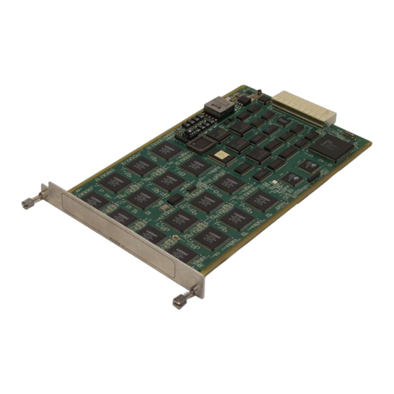
The Modem-16 Module provides no external interfaces. Both the network and customer interfaces are provided on other ATLAS components. Information is passed to and from the Modem-16 Module via ATLAS’ internal bussing scheme. See Figure 1-2 for an illustration of the Modem-16 Module. - Page 14 Chapter 1. Introduction Physical Description Specifications Modem-16 Module User Manual 61200181L1-1...
-
Page 15: Chapter 2. Installation
Remove the cover plate (corresponding to the slot in which the Modem-16 Module will be installed) from the ATLAS chassis rear panel. Slide the Modem-16 Module into the ATLAS chassis until the module is posi- tioned firmly against the front of the ATLAS unit. -
Page 16: Power-Up And Initialization
Failed Self-Test POWER-UP AND INITIALIZATION When the Modem-16 Module is inserted into the ATLAS chassis, the front panel STATUS indicator blinks red, yellow, and green for a time. Previously configured settings for the Modem-16 Module are automatically restored upon power-up. -
Page 17: Chapter 3. Operation
Operation Chapter 3 OVERVIEW You can configure and control the Modem-16 Module from several sources, as shown in Table 3-1. The ATLAS User Manual provides detailed instructions on operating each of the supported management approaches. The remainder of this chapter describes the menu items available for managing the Modem-16 Module using the terminal menu. -
Page 18: Menu Access
Displays the module type currently installed in the slot or the module type you plan to install in the slot. If a Modem-16 Module is installed, the Type field auto- matically defaults to M56K-16 (the Modem-16 Module). You can use this field to preconfigure the system before installing modules by specifying the module that you want to install into each slot. - Page 19 Displays whether there is an alarm condition on the Modem-16 Module. Press Enter in this field to activate the Alarm menu. Test Read security: 5 Displays whether the Modem-16 Module is executing a test. Press Enter in this field to activate the Test menu. State Read security: 5 Displays whether the module is online or offline.
-
Page 20: Modem-16 Module Submenus
Modem-16 should take less than two minutes. MODEM-16 MODULE SUBMENUS Figure 3-2 shows the Menus submenus for the Modem-16 Module. The following sections describe these options. Figure 3-2. Menus Panel Modem-16 Module User Manual 61200181L1-1... -
Page 21: Info
Read Security: 5 Displays the Modem-16 Module’s serial number in a read-only field. Board Revision Read Security: 5 Displays the printed circuit board revision of the Modem-16 Module in a read-only field. Firmware Revision Read Security: 5 Displays the firmware revision of the Modem-16 Module in a read-only field. -
Page 22: Figure 3-4. Status Submenu
Figure 3-4. Status Submenu Resource Read Security: 5 Indicates the resource number of the analog resource listed. On the Modem-16 Module, analog resources are numbered 1-16 and digital ISDN resources are numbered 17-32. Resource Status Read Security: 5 Indicates the current status of the particular analog call resource and displays new activity as it occurs. - Page 23 This information may be used when troubleshooting modem connection problems with the Modem-16 Module. Analog Resource Connection Statistics Read Security: 5 This menu option displays the connection statistics for the analog resources avail- able on the Modem-16 Module (see Figure 3-5). 61200181L1-1 Modem-16 Module User Manual...
-
Page 24: Figure 3-5. Analog Resources Connection Status Submenu
Read Security: 5 Displays the input and output statistics for the analog resources available on the option module (see Figure 3-6). All statistics are for the current active call and are reset once the call becomes disconnected. Modem-16 Module User Manual 61200181L1-1... -
Page 25: Figure 3-6. Analog Resources I/O Statistics Submenu
Modem-16 Module Submenus Chapter 3. Operation Status • Transmit direction refers to data flow from the Modem-16 Module analog re- source to the remote client modem. • Receive direction refers to data flow from the remote client modem to the Mo- dem-16 Module analog resource. -
Page 26: Figure 3-7. Digital Resource Session Status Panel
Figure 3-7. Digital Resource Session Status Panel Resource Read Security: 5 Indicates the resource number of the digital resource listed. On the Modem-16 Module, analog resources are numbered 1-16 and digital resources are numbered 17-32. Resource Status Read Security: 5 Indicates the current status of the particular digital call resource. -
Page 27: Figure 3-8. Digital Resource Connection Statistics Panel
Digital Resource Connection Statistics Read Security: 5 Displays the connection statistics for the digital resources available on the Modem-16 Module (see Figure 3-8). Figure 3-8. Digital Resource Connection Statistics Panel 61200181L1-1 Modem-16 Module User Manual... - Page 28 Digital Resource I/O Statistics Read Security: 5 Displays the input and output statistics for the digital resources available on the Modem-16 Module (see Figure 3-9). All statistics are for the current active call and are reset once the call becomes disconnected. •...
-
Page 29: Figure 3-9. Digital Resource I/O Statistics Panel
Displays the number of receiver overruns which occurred on the digital resource during the current call. A receiver overrun occurs when the client device transmits data too fast for the Modem-16 Module digital resource to keep up. This causes data to be lost. Once the call is disconnected, this parameter is reset. -
Page 30: Configuration
Figure 3-10. Analog Resource Panel Resource Read Security: 5 Indicates the resource number of the analog resource listed. On the Modem-16 Module, analog resources are numbered 1-16 and digital resources are numbered 17-32. Resource Status Read Security: 5 Indicates the current status of the particular analog call resource. Table 3-5 defines the status display values. -
Page 31: Table 3-5. Configuration Analog Call Resource Status
Reset a specific analog resource on the modem module. Any calls currently active will be dropped. Digital Resource Read Security: 5 Displays the configuration parameters for the digital resources available on the modem module. 61200181L1-1 Modem-16 Module User Manual 3-15... -
Page 32: Table 3-7. Configuration Digital Call Resource Status
Configuration Resource Read Security: 5 Indicates the resource number of the digital resource listed. On the Modem-16 Module, analog resources are numbered 1-16 and digital resources are numbered 17-32. Resource Status Read Security: 5 Indicates the current status of the particular digital call resource. Table 3-7 defines the status display values. -
Page 33: Atlas Features Used With Modem-16 Module Options
ATLAS FEATURES USED WITH MODEM-16 MODULE OPTIONS In addition to the Modem-16 Module menu items, two additional ATLAS menu items may be operated in conjunction with the Modem-16 Module. These are Fac- tory Restore and System Self-test. Factory Restore... - Page 34 Chapter 3. Operation ATLAS Features used with Modem-16 Module Options System Self-Test 3-18 Modem-16 Module User Manual 61200181L1-1...
- Page 35 3-8 client-to-server data rates 1-3 connection completions, number of 3-8 configuration submenu 3-14 connection failures, number of 3-8 configuring Modem-16 Module 3-1 connection rate statistics 3-8 connection statistics 3-7 data compression mode 3-7 data format 1-3...
- Page 36 Modem-16 3-3 digital resources 1-3 status submenu 3-5 framing options 1-3 submenus line code 1-3 configuration 3-14 line rate 1-3 info 3-5 modules menu status 3-5 alarm 3-3 menu (submenus) 3-3 Index-2 Modem-16 Module User Manual 61200181L1...
- Page 37 3-7 system self-test 3-17 type menu 3-2 terminal menu structure 3-1 viewing module status 1-1 test menu 3-3 tests power up 2-2 warranty 2-2 self-test, failed 2-2 system self-test 3-17 61200181L1 Modem-16 Module User Manual Index-3...
- Page 38 Index Index-4 Modem-16 Module User Manual 61200181L1...
- Page 39 (888) 4ADTRAN Repair and Return If ADTRAN Technical Support determines that a repair is needed, Technical Support will coordinate with the Customer and Product Service (CAPS) department to issue an RMA number. For information regarding equipment currently in house or possible fees associated...
Need help?
Do you have a question about the Modem-16 Module and is the answer not in the manual?
Questions and answers