Table of Contents
Advertisement
Quick Links
Vehicle identification no:
Manufacturer
FAUN GmbH
Postfach 10 01 08
D - 91205 Lauf a.d. Pegnitz
Phone: +49 (0) 9123 185 - 0
Fax: +49 (0) 9123 7 53 20
TX: 62 29 90
Operating, Service
Maintenance Manual
ATF 220G - 5
WFN5 RUG R1 62036...
and
After-Sales Service:
TADANO FAUN GmbH
Postfach 10 02 64
D - 91205 Lauf a.d. Pegnitz
Phone: +49 (0) 9123 955 - 0
Fax: +49 (0) 9123 18 51 55
TX: 62 29 90
Advertisement
Chapters
Table of Contents

Related Manuals for Tadano FAUN ATF 220G-5


Summary of Contents for Tadano FAUN ATF 220G-5
- Page 1 Vehicle identification no: WFN5 RUG R1 62036… Manufacturer After-Sales Service: FAUN GmbH TADANO FAUN GmbH Postfach 10 01 08 Postfach 10 02 64 D - 91205 Lauf a.d. Pegnitz D - 91205 Lauf a.d. Pegnitz Phone: +49 (0) 9123 185 - 0...
- Page 3 Dear Customer, We have gone to great lengths to provide the conditions for a long service life of your FAUN crane. High-grade coatings, multi-layer paint systems and high-performance application procedures with a high process reliability characterize the excellent visual appearance of our FAUN cranes. Service and upkeep are indispensable to maintain this finish: Paint takes some time to develop its maximum resistance.
- Page 5 TABLE OF CONTENTS 0015_EN_ALLGE_I_00_00_00...
- Page 7 TABLE OF CONTENTS P R E F A C E How to use this Operating Manual Technical data, operation, maintenance, troubleshooting Handling of this Operating Manual Mounting locations of the vehicle identification number and of the nameplates 0020_EN_FA036_I_01_00_00 1/22 2002-12...
-
Page 8: Table Of Contents
TABLE OF CONTENTS P a r t A ) T e c h n i c a l D e t a i l s General technical details (chassis) Dimensions and weights Driving performance data (according to DIN 70020) Details of components (chassis) Engine Gearbox Transfer box... - Page 9 TABLE OF CONTENTS P a r t A ) T e c h n i c a l D e t a i l s ( c o n d ’ t . ) Technical details of components (superstructure) Engine Hydraulic system Hoisting gear Telescopic boom...
- Page 10 TABLE OF CONTENTS P a r t B 0 ) S a f e t y I n s t r u c t i o n s Requirements and conditions for vehicles used in public road traffic. Important instructions regarding the load ratings of tires depending on the maximum travelling speeds and the stress to which the rims are subject Instructions for the crane operator Applications planning...
- Page 11 TABLE OF CONTENTS P a r t B ) O p e r a t i n g I n s t r u c t i o n s B 1 ) C h a s s i s General instructions concerning operation of the vehicle Warning and instruction plates Components, assemblies - installation location and position...
- Page 12 TABLE OF CONTENTS P a r t B ) O p e r a t i n g I n s t r u c t i o n s (cont’d) B 1 ) C h a s s i s Gearshift and driving operation Gearbox Transfer box...
- Page 13 TABLE OF CONTENTS P a r t B ) O p e r a t i n g I n s t r u c t i o n s (cont’d) B 1 ) C h a s s i s 10 Attachments, optional equipment and accessories 10.1 Acoustic reversing signal - warning device 10.2 City / country horn (Supertone horn)
- Page 14 TABLE OF CONTENTS P a r t B ) O p e r a t i n g I n s t r u c t i o n s B 2 ) S u p e r s t r u c t u r e General information about operation Warning and instruction plates Location of the warning and instruction plates...
- Page 15 TABLE OF CONTENTS P a r t B ) O p e r a t i n g I n s t r u c t i o n s (cont’d) B 2 ) S u p e r s t r u c t u r e Crane movements in no-load condition Instructions regarding actuation of the crane control levers Actuation of the hoisting gear (main hoisting gear)
- Page 16 TABLE OF CONTENTS P a r t B ) O p e r a t i n g I n s t r u c t i o n s (cont’d) B 2 ) S u p e r s t r u c t u r e 11 Attachments, optional equipment and accessories 11.1 Optional equipment mentioned in other sections 11.2 Positioning the double ladder for mounting the jibs, and for access to the crane superstructure...
- Page 17 TABLE OF CONTENTS P a r t C ) S e r v i c e a n d M a i n t e n a n c e C 1 ) C h a s s i s General information Before starting service and maintenance work Welding and straightening work...
- Page 18 TABLE OF CONTENTS P a r t C ) S e r v i c e a n d M a i n t e n a n c e (cont’d) C 1 ) C h a s s i s Axles Checking the oil level in the axle drive assemblies of the steering driven axles and the planetary gears Oil change in the axle drive assemblies and planetary gears...
- Page 19 TABLE OF CONTENTS P a r t C ) S e r v i c e a n d M a i n t e n a n c e (cont’d) C 1 ) C h a s s i s 11 Brakes 11.1 Drainage valves in the compressed air tanks 11.2 Air drier...
- Page 20 TABLE OF CONTENTS P a r t C ) S e r v i c e a n d M a i n t e n a n c e (cont’d) C 1 ) C h a s s i s 15 Driver’s cab 15.1 Warm water heating 15.2 Wiper-blade elements / washing system...
- Page 21 TABLE OF CONTENTS P a r t C ) S e r v i c e a n d M a i n t e n a n c e C 2 ) S u p e r s t r u c t u r e Maintenance intervals Maintenance schedule Engine...
- Page 22 TABLE OF CONTENTS P a r t C ) S e r v i c e a n d M a i n t e n a n c e (cont’d) C 2 ) S u p e r s t r u c t u r e Swing mechanism Check for correct oil level and leakage Oil change...
- Page 23 TABLE OF CONTENTS P a r t C ) S e r v i c e a n d M a i n t e n a n c e (cont’d) C 2 ) S u p e r s t r u c t u r e Electrical equipment Batteries Three-phase generator...
- Page 24 TABLE OF CONTENTS P a r t D ) D i a g r a m s D 1 ) D i a g r a m s o f c h a s s i s Diagrams Electric circuit diagrams Chassis (99707782035) ABV (99707782035) Gearbox control (99707782035)
- Page 25 TABLE OF CONTENTS P a r t D ) D i a g r a m s D 2 ) D i a g r a m s o f s u p e r s t r u c t u r e Electric circuit diagrams Chassis control system (99707792040) Superstructure (99707792040)
- Page 26 TABLE OF CONTENTS P a r t E ) C r a n e t e s t i n g i n s t r u c t i o n s Inspection of supporting steel structures Guidelines for areas to be checked Inspection of the hook blocks Inspection for widening of the hook mouth Inspection for wear...
- Page 27 TABLE OF CONTENTS P a r t F ) T r o u b l e s h o o t i n g F 1 ) C h a s s i s Troubleshooting Engine Gearbox Transfer box Axle differential locks and drive assemblies Hydraulic system in general Steering system - mechanical section Steering system - hydraulic / electrical section...
- Page 28 TABLE OF CONTENTS P a r t F ) T r o u b l e s h o o t i n g (cont’d) F 4 ) C o n n e c t i o n d i a g r a m C h a s s i s Connection diagram - Chassis P a r t G ) A n n e x G 1 ) C h a s s i s...
- Page 29 PREFACE 0025_EN_ALLGE_V_00_00_00...
- Page 31 How to use this Operating Manual How to use this Operating Manual This Operating Manual provides vital information which is a prerequisite for working safely with the machine. The chassis (undercarriage) and the superstructure are covered by separate sections. This Operating Manual is intended primarily for the crane operator and for maintenance specialists. It must be available to the operator and maintenance staff at all times.
- Page 32 How to use this Operating Manual Memo: 2002-12 0030_EN_FA036_V_01_00_00_FA029...
- Page 33 After-Sales Service Department of TADANO FAUN will be pleased to perform such repairs for you. Use only genuine TADANO FAUN spare parts. We cannot accept any warranty claims for damage resulting from the neglect of the Operating Manual and the information it contains, or due to the crane carrier being used outside its intended fields of application.
- Page 34 Technical data, operation, maintenance, troubleshooting Memo: 2002-12 0035_EN_FA036_V_02_00_00_FA029...
- Page 35 Handling of this Operating Manual Handling of this Operating Manual This Operating Manual covers the machine model supplied plus any optional equipment that may be avail- able. To find the information you need, please consult the Table of Contents. Moreover, the headline of the corresponding chapter appears in the header of each page.
- Page 36 Handling of this Operating Manual Memo: 2002-12 0040_EN_FA036_V_03_00_00_FA029...
- Page 37 Mounting locations of the vehicle identification number and of the nameplates Mounting locations of the vehicle identification number and of the nameplates These plates are provided on the chassis in the following locations: The vehicle identification number (1) is stamped on the frame, on the right side of the chassis, between the and 3 axles.
- Page 38 Mounting locations of the vehicle identification number and of the nameplates Memo: 2002-12 0045_EN_FA036_V_04_00_00...
- Page 39 Part A Technical Details 0050_EN_ALLGE_A_00_00_00...
-
Page 41: General Technical Details (Chassis)
General technical details (chassis) General technical details (chassis) Dimensions and weights 1.1.1 Dimensions of the chassis 3000 with tires 445/95 R 25 (16.00 R 25) Overall width 3200 with tires 525/80 R 25 (20.5 R 25) Overall length 15105 Length of chassis 13425 Overall height 3990... -
Page 42: Driving Performance Data (According To Din 70020)
General technical details (chassis) Driving performance data (according to DIN 70020) In manoeuvring mode, speeds as of 0 km/h are possible. At the same time, the clutch position is controlled electronically via the accelerator pedal position (slipping clutch). With the clutch engaged, a minimum speed of 1.0 km/h is possible in the 1 gear (off-road), at 800 rpm. -
Page 43: Details Of Components (Chassis)
Details of components (chassis) Details of components (chassis) Engine Mercedes-Benz 8 cylinder diesel engine, type OM502LA, certified for EUROMOT III A and EPA Tier 3, water-cooled, hydrostatically driven fan, controlled by thermostat. Power KW (HP) 380 (517) at r.p.m. 1,800 Max. -
Page 44: Transfer Box
Details of components (chassis) Transfer box Two-step transfer box, type VG 3750, with on-road and off-road gear, neutral position for towing. Reduction ratios: On-road gear: 0.8 Off-road gear: 1.836 Axles Drive 10x6 Drive 10x8 1st axle: Steering axle, non-driven Driven, steering axle, i = 8.47 2nd axle: Driven, steering axle, I = 8.47 Driven, steering axle (connectable), i = 8.47... -
Page 45: Wheels And Tires
Details of components (chassis) Wheels and tires 2.7.1 Rims Steel disc rims 9.50-25 / 1.7 (385/95 R 25/14.00 R 25)**). Steel disc rims 11.00-25 / 1.7 (445/95 R 25/16.00 R 25). Steel disc rims 17.00-25 / 1.7 (525/80 R 25/20.5 R 25) 2.7.2 Tires Tires 385/95 R 25 (14.00 R25) with on-road and off-road tread pattern**). -
Page 46: Steering
Details of components (chassis) Steering ZF Servocom dual-circuit hydraulic steering, mechanical with hydraulic assistance. The permanent steering is effective on the 1 and 2 axles with mechanical connection to the steering gear. In on-road mode, the 4 and 5 axles are steered electronically depending on the speed according to the current steering angles of the 1 and 2 axles. -
Page 47: Driver's Cab
Details of components (chassis) 2.12 Driver’s cab Front cab for two persons, of steel/plastic composite design, windshield made of laminated glass, side panes made of tempered glass, side panes movable. Driver’s and passenger’s seats with integrated three-point seat belt systems, with height, inclination and length adjustment, and headrests. -
Page 48: Fuel System
Details of components (chassis) 2.16 Fuel system Approx. 530 l fuel tank with lockable cap. 2.17 Standard equipment Tools, first-aid kit, warning light, warning triangle, 4 wheel chocks, fire extinguisher in the carrier cabin, inspection by TÜV (German technical inspection authority). 2.18 Painting Single-color painting. -
Page 49: Technical Details Of Components (Superstructure)
Technical details of components (superstructure) Technical details of components (superstructure) Engine Mercedes-Benz 6 cylinder diesel engine, type OM 906 LA, certified for EUROMOT III A and EPA Tier 3, water-cooled. The engine speed can be varied progressively via a pedal. Power kW (HP) 138 (188) -
Page 50: Telescopic Boom
Technical details of components (superstructure) Telescopic boom Seven-section telescopic boom made of high-tensile fine grain steel, consisting of a basic boom and 6 telescopic elements with 1 telescopic cylinder to extend and retract the telescopes. The telescopes are extended and retracted fully automatically, and locked fully automatically in the working position in question. The telescopes can be extended and retracted hydraulically under partial load. -
Page 51: Superstructure Cabin
Technical details of components (superstructure) Superstructure cabin Crane cabin (extra-large and optimized ergonomically speaking) in steel / plastic design with sliding door, safety glass with tinted panes, electrically actuated hinged windscreen, glued-in skylight made of bullet-proof safety glass, and hinged backlight. To ensure an optimum vision during crane work, the work place can be tilted progressively via the FAUN inclination technique integrated in the cab. -
Page 52: Counterweight
Technical details of components (superstructure) 3.10 Counterweight Total counterweight 71t, divisible. Partial counterweight can be deposited via hydraulic cylinders. Actuation from the crane cabin. The swing radius is 4.98 m; up to a 12t counterweight, the width is 3.0m, up to 47t, the width is 3.6m, up to 71t, the width is 5.6m. -
Page 53: Heating System
Technical details of components (superstructure) 3.11 Heating system Engine-fed warm water heater and autonomous auxiliary heating with engine pre-heating (water heater Webasto Thermo 90S), diesel-operated. 3.12 Superstructure frame Torsion-resistant welded structure with single-race ball-bearing slewing device with external gearing, rotating through 360°. -
Page 54: Optional Equipment
Technical details of components (superstructure) 3.15 Optional equipment 1. 5.4 m jib which can be positioned at offset angles of 0°/20°/40°, with AML extension feature, hoist limit switch and ladder for mounting the fly jib. It features 2 pulleys and a maximum lifting capacity of 33 t. 2. -
Page 55: Noise Level When The Engine Is Operating Under Load And At Working Speed (1,500 R
Technical details of components (superstructure) 3.16 Noise level when the engine is operating under load and at working speed (1,500 r.p.m) Noise level when Noise level when Noise at a distance superstructure cabin is superstructure cabin is open of 7 m closed (driver's ear) (driver's ear) - Page 56 Technical details of components (superstructure) Memo: 0065_EN_FA036_A_03_00_00 2003-01...
-
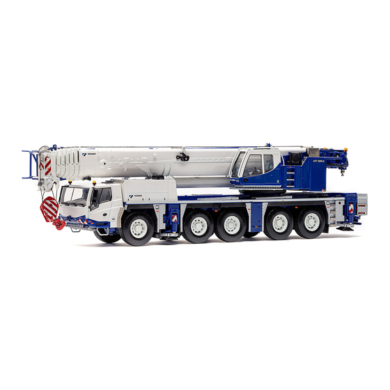
Page 57: Illustration Of The Vehicle
Illustration of the vehicle Illustration of the vehicle Lenkschema = Steering pattern; Strasse = On-road gear; Baustelle = Construction site; durch Federung = by suspension 0070_EN_FA036_A_04_00_00 2001-06... - Page 58 Illustration of the vehicle Memo: 0070_EN_FA036_A_04_00_00 2001-06...
-
Page 59: Notes Referring To The Load (Lifting Capacity) And Supporting Forces Charts
Notes referring to the load (lifting capacity) and supporting forces charts Notes referring to the load (lifting capacity) and supporting forces charts Explanation regarding a load chart The following diagram represents a load chart example. The load charts are classified in various categories, depending on the crane's working position. For each job, the operator must select the table which is as close as possible to the actual working position. -
Page 60: Supporting Forces Charts
Notes referring to the load (lifting capacity) and supporting forces charts Supporting forces charts Besides the load chart column, the supporting forces charts contain the maximum supporting forces which might arise when the crane is supported by outriggers, when the loads specified in the load charts are slewed through 360°. - Page 61 Part B0 Safety Instructions 0080_EN_ALLGE_B0_00_00_00...
-
Page 63: Requirements And Conditions For Vehicles Used In Public Road Traffic
Requirements and conditions for vehicles used in public road traffic. B0-1 SAFETY INSTRUCTIONS FOR DRIVING AND CRANE OPERATION Requirements and conditions for vehicles used in public road traffic. The crane has been approved for use in public road-traffic, and has been registered by the competent, authorized government agencies subject to the appropriate legal provisions. - Page 64 Requirements and conditions for vehicles used in public road traffic. B0-1 (cont'd.) 1 Requirements and conditions for vehicles used in public road traffic. • Attachments and superstructure components must be secured so that they cannot slip or fall down. • Objects which are not sufficiently secured must not be deposited on the platforms of the chassis and the superstructure.
-
Page 65: Important Instructions Regarding The Load Ratings Of Tires Depending On The Maximum Travelling Speeds And The Stress To Which The Rims Are Subject
Requirements and conditions for vehicles used in public road traffic. B0-1 Important instructions regarding the load ratings of tires depending on the maximum travelling speeds and the stress to which the rims are subject • The axle loads of the crane carrier have to be observed in view of the legal regulations valid in the country where the machine is to be registered. - Page 66 Requirements and conditions for vehicles used in public road traffic. B0-1 Memo: 0085_EN_FA036_B0_01_00_00 2003-01...
-
Page 67: Instructions For The Crane Operator
Instructions for the crane operator B0-2 Instructions for the crane operator As the operator of the mobile crane, you have a number of responsibilities, i.e.: • You should ensure that the mobile crane is always in a safe operating and road condition. Recurrent inspections according to VBG 9, §... -
Page 68: Applications Planning
Instructions for the crane operator B0-2 Applications planning The basis of trouble-free operation is thorough planning of the application. In good time before the operator drives the machine to the site of operation, he must obtain or provide himself with all the data and documents required for the work as a whole, especially as regards: •... -
Page 69: Steps To Be Taken Before Crane Operation
Instructions for the crane operator B0-2 Steps to be taken before crane operation • The ground conditions on the site of crane operation should be checked with regard to stability (load-bearing capacity); if necessary, the ground should be reinforced with sheet metal plates. •... - Page 70 Instructions for the crane operator B0-2 2.2.1 Checking the ground quality A fundamental prerequisite of safe crane work is that the machine is used on sufficiently solid ground. The choice of the appropriate site of installation for the crane is also decisive for correct execution of the planned work.
- Page 71 Instructions for the crane operator B0-2 2.2.2 Admissible ground pressures (excerpt from German Industrial Standard DIN 1054) Nature of soil daN/cm2 Loosely tipped soil, not artificially compacted: Natural soil, obviously virgin soil: Mud, turf, moorland Fine to medium-fine sand Coarse sand to gravel Binding soil: Very soft Soft...
- Page 72 Instructions for the crane operator B0-2 2.2.3 Distance of the crane from ditches, slopes and excavations Once the site of installation of the crane has been chosen, it must be ensured that the crane is not installed too close to ditches, slopes or excavations. There is a risk that the edge of the slope or the excavation might slip away under the load of the outriggers, causing the crane to tip over.
-
Page 73: Supporting By Outriggers
Instructions for the crane operator B0-2 Supporting by outriggers It is extremely important that the outriggers are extended according to the selected load chart and to the extension width specified there, and that the load is divided up between all outriggers. Make sure that the crane's actual supporting base does not fall short of the extension width specified in the selected load chart. -
Page 74: Counterweight
Instructions for the crane operator B0-2 (cont'd.) 2.3 Supporting by outriggers Besides the correct and safe supporting of all outrigger floats and besides complying with the correct extension width, the horizontal alignment of the crane's plane of rotation is extremely important for safe crane operation. In the case of a crane with a boom of 60 m, which is placed at an inclination angle of 5°, the working radius is increased by approx. -
Page 75: Hoist Winch And Reeving Of The Winch Rope
Instructions for the crane operator B0-2 Hoist winch and reeving of the winch rope The lifting capacity of a crane depends on the traction force of the hoist winch and on the selected number of rope falls. When the work is effected with "direct" rope arrangement (= one rope fall), the crane can only lift the weight which can be pulled by the hoist winch. - Page 76 Instructions for the crane operator B0-2 (cont'd.) 2.6 Taking account of the wind speeds The following table contains a few reference values enabling the assessment of the prevailing wind speeds. Wind intensity Wind speed Evaluation of wind Beaufort Description km/h in continental areas scale calm...
- Page 77 Instructions for the crane operator B0-2 (cont'd.) 2.6.1 Influence of and attention to the action of wind DANGER Before the crane operator starts any crane work, he has to obtain information about the wind speeds which must be expected; if necessary, he may have to check the wind speeds which may occur with the competent meteorological authority.
- Page 78 Instructions for the crane operator B0-2 noch: 2.6.1 Influence of and attention to the action of wind Diagram 1 - Dynamic pressure - Wind velocity (km/h or m/s) 0090_EN_FA036_B0_02_00_00_FA029 12/24 2003-01...
- Page 79 Instructions for the crane operator B0-2 noch: 2.6.1 Influence of and attention to the action of wind Diagram 2 - Load wind area - admissible load wind area A incl. c wzul 0090_EN_FA036_B0_02_00_00_FA029 13/24 2003-01...
-
Page 80: Hand Signals Recommended For Communication Between The Crane Operator And His Assistant
Instructions for the crane operator B0-2 Hand signals recommended for communication between the crane operator and his assistant During all intended crane movements (with or without load), the crane operator must always have the load or the load lifting device in his field of vision. Loads fixed by hand may only be moved by the crane operator after he has received a corresponding signal from the person fixing the load or from another responsible person who has been determined in advance. -
Page 81: Work In The Vicinity Of Electrical Overhead Lines
Instructions for the crane operator B0-2 Work in the vicinity of electrical overhead lines When crane work is performed near electrical overhead lines, serious accidents may occur if the crane moves the boom or the load too close to, or even touches, the overhead line. In case of voltages below 1000 V, only direct contact with the overhead line will in general involve a risk;... -
Page 82: How To Behave In Case Of Spark-Over (If The Crane Has Touched The Power Line)
Instructions for the crane operator B0-2 How to behave in case of spark-over (if the crane has touched the power line) If an overhead line has been touched or a current spark-over has occurred in spite of all precautions, please observe the following instructions: •... -
Page 83: Grounding The Crane And The Load
Instructions for the crane operator B0-2 2.10 Grounding the crane and the load During crane work, the crane and the load might be charged electrically under certain circumstances. This may occur, e.g., during work near powerful radio transmitters or RF change-over stations. The crane may be electrified especially if the crane's outrigger floats are supported with insulating material (e.g. -
Page 84: Work In The Vicinity Of Supply Lines
Instructions for the crane operator B0-2 2.11 Work in the vicinity of supply lines DANGER Particular caution is required in the area of exposed supply lines. Damage to such lines and any resulting leakage may have imprevisible consequences. Before crane work begins, it must be ensured which fluids are transported in the supply lines. To this effect, the operating company involved must definitely be contacted. -
Page 85: Notes Regarding Work With Two Cranes
Instructions for the crane operator B0-2 2.13 Notes regarding work with two cranes Sometimes two cranes may be required to move bigger and considerably heavy loads. DANGER Executing such work requires a high degree of operator experience and attention, as otherwise there is a considerable R i s k o f a c c i d e n t s ! When working with two cranes, take note of the following instructions:... -
Page 86: Crane Application In Accordance With The Intended Use
Instructions for the crane operator B0-2 2.15 Crane application in accordance with the intended use Crane application in accordance with the intended use is operation as an assembly crane, and consequently, lifting and transporting of loads. The machine has been designed and built only for operation in areas where there is no risk of explosion. 2.16 Crane application not in accordance with the intended use Crane application not in accordance to the intended use includes piling, vibrating and clamshell operation,... - Page 87 Instructions for the crane operator B0-2 2.17.2 Causes for faults during crane operation Such causes and faults may occur during crane operation for the following reasons: • the crane is not mounted with the outrigger beams extended and secured as specified in the load chart; •...
-
Page 88: Fire, Smoke, Inflammation And Explosion Hazard
Instructions for the crane operator B0-2 2.17.3 Servicing faults which may cause accidents • Lack of oil, grease or anti-freeze agent in the various assemblies. • Only the specified lubricants and oils may be used in accordance with the chart of approved lubricants. •... -
Page 89: Instructions And Regulations Concerning The Compressed Air Tanks Installed In Air-Operated Braking Systems
Instructions for the crane operator B0-2 2.19 Instructions and regulations concerning the compressed air tanks installed in air-operated braking systems • The compressed air tanks installed are in conformance with the EEC (EU) directive 87/404/EEC and are approved exclusively for air-operated brake systems. •... - Page 90 Instructions for the crane operator B0-2 Memo: 0090_EN_FA036_B0_02_00_00_FA029 24/24 2003-01...
-
Page 91: Instruction Sheet For Overload Safety Devices For Boom Cranes (Excerpts)
Instruction Sheet for Overload Safety Devices for Boom Cranes B0-3 (excerpts) Instruction Sheet for Overload Safety Devices for Boom Cranes (excerpts) Issued by: VDMA-Fachgemeinschaft Hebezeuge im Verein Deutscher Maschinenbau-Anstalten e.V. The hydraulic crane supplied to you has been equipped with an overload safety device (automatic safe load indicator), which serves to shut off the crane when the admissible load moment is being exceeded. - Page 92 Instruction Sheet for Overload Safety Devices for Boom Cranes B0-3 (excerpts) Instruction Sheet for Overload Safety Devices for Boom Cranes (cont'd.) Safe operation of the machine and crane work free of accidents depend to a large extent on careful compli- ance with these instructions.
- Page 93 Part B Operating Instructions 0100_EN_ALLGE_B_00_00_00...
- Page 95 Part B1 Operating Instructions Chassis 0105_EN_ALLGE_B1_00_00_00...
-
Page 97: General Instructions Concerning Operation Of The Vehicle
General instructions concerning operation of the vehicle B1-1 General instructions concerning operation of the vehicle All the controls and gauges required for operation of the vehicle are installed in the cabins of the chassis and/or the superstructure. Before the driver puts the vehicle into operation, it is essential that he has read part "B" and “B0” of this manual. -
Page 98: Warning And Instruction Plates
General instructions concerning operation of the vehicle B1-1 Warning and instruction plates Nameplate Check wheel nuts. For the first time after 50 km brake system comprises traveled, then after 100 km, and plastic piping. once more after another 200 km Caution during drilling, welding traveled and grinding work. - Page 99 General instructions concerning operation of the vehicle B1-1 (cont'd.) 1.1 Warning and instruction plates Wheel chocks Refer to Operating Manual. DIFFERENTIAL LOCKS must never be engaged while driving in curves, but only briefly to overcome an obstacle. Accelerate carefully when driving while the crane is mounted.
- Page 100 General instructions concerning operation of the vehicle B1-1 (cont'd.) 1.1 Warning and instruction plates 24 V 12 V Instruction plate Instruction plate Plate Only in case of optional feature "Emergency operation of the Weight unit 250 kg superstructure controlled from the chassis".
- Page 101 General instructions concerning operation of the vehicle B1-1 1.1.1 Drawing of chassis showing the location of warning and instruction plates The following diagram shows the position and the location of all the warning and instruction plates mounted to the chassis. 0110_EN_FA036_B1_01_00_00 5/14 2002-12...
- Page 102 General instructions concerning operation of the vehicle B1-1 Memo: 0110_EN_FA036_B1_01_00_00 6/14 2001-06...
- Page 103 General instructions concerning operation of the vehicle B1-1 Memo: 0110_EN_FA036_B1_01_00_00 7/14 2003-01...
-
Page 104: Components, Assemblies - Installation Location And Position
General instructions concerning operation of the vehicle B1-1 Components, assemblies - installation location and position 1 Steering gear 26 Test connectors / test panel, compressed air 2 Miter gear of steering system system 3 Air conditioning**) 27 Compressed air tank 4 Tow lugs 28 Trailer coupling device**) 5 Sliding coupling... - Page 105 General instructions concerning operation of the vehicle B1-1 (cont'd.) 1.3 Components, assemblies - installation location and position 0110_EN_FA036_B1_01_00_00 9/14 2002-12...
- Page 106 General instructions concerning operation of the vehicle B1-1 Memo: 0110_EN_FA036_B1_01_00_00 10/14 2001-06...
-
Page 107: Transport Condition Of The Vehicle When Used In Public Road Traffic
General instructions concerning operation of the vehicle B1-1 Transport condition of the vehicle when used in public road traffic When the crane is used in public road traffic, it is essential that the conditions and prescriptions specified in the expertise of the Technical Inspection Authority (German TÜV) are observed. •... - Page 108 General instructions concerning operation of the vehicle B1-1 (cont'd.) 1.4 Transport condition of the crane when used in public road traffic • The engine in the superstructure has been stopped. • Ignition starter switch for the superstructure engine in position 0. •...
- Page 109 General instructions concerning operation of the vehicle B1-1 1.4.1 Transport condition, graphic display The safety accessories (warning triangles, first-aid kit, warning lights and fire extinguishers) can be stored in the storage boxes in the driver's cabin. The wheel chocks (5) **) have been arranged on the left, in the storage box of the driver’s cab. A tool box **) (3) is located at the rear of the vehicle.
-
Page 110: Wheel Chocks
General instructions concerning operation of the vehicle B1-1 Wheel chocks The vehicle is equipped with wheel chocks (folding wheel chocks) pursuant to the legal provisions. The wheel chocks (folding wheel chocks) have been arranged on the left, in the storage box of the driver’s cab (see item 1.4.1). - Page 111 Driver’s cab B1-2 Memo: 0115_EN_FA036_B1_02_01_00_FA029 1/10 2002-12...
-
Page 112: Driver's Cab
Driver’s cab B1-2 Driver’s cab Explanation of the control elements and of the equipment Lateral bordering light Rotary beacon Seat belt Compartment for installation of auxiliary heating Storage box Ashtray Refrigerator box **) Gearbox control device Electronic control unit for actuation of rear axle steering Radio Plugbox 24 V Plugbox 12 V... - Page 113 Driver’s cab B1-2 Driver’s cab „X“ 0115_EN_FA036_B1_02_01_00_FA029 3/10 2002-12...
- Page 114 Driver’s cab B1-2 Memo: 0115_EN_FA036_B1_02_01_00_FA029 4/10 2001-06...
-
Page 115: Front Lid
Driver`s cab B1-2 Front lid Various assemblies have been arranged below the front cover where they are easily accessible for maintenance and repair work. 2.3.1 Unlocking the front lid The lever used to unlock the front lid is installed on the left below the instrument panel. - Page 116 Driver`s cab B1-2 2.3.3 Explanation of the devices located under the front lid 1 Brake valve 2 Servo-motor for change-over flap for outside air / circulating air 3 Change-over flap for outside air / circulating air 4 Air inlet, heating/ventilation 5 Electronic system, engine ADM 6 Gearbox control system 7 Voltage transformer 24/12 V...
-
Page 117: Seat Adjustment
Driver`s cab B1-2 Seat adjustment The driver's and the passenger's seat afford maximum comfort. Both seats are equipped with pneumatic suspension and thus adjust automatically to the driver's weight. The downwards or upwards deflection amounts to 20 mm each. To adjust the seats optimally as regards their position with reference to the control elements, the seats' longitudinal position and the inclination of the seats' surfaces can be adjusted. - Page 118 Driver`s cab B1-2 2.4.3 Height adjustment To adjust the seat steplessly in height by approx. 100 mm: - Pull the control lever - height adjustment - (3) upwards and keep it in this position, until the seat is adjusted to the desired vertical position. 2.4.4 Quick-lowering feature With the quick seat lowering feature, the seat can be lowered entirely so that the driver can leave his cab...
-
Page 119: Adjustment Of The Steering Wheel
Driver`s cab B1-2 Adjustment of the steering wheel The steering wheel can be adjusted to the driver's stature easily and progressively by means of an air-assisted inclination and height adjustment. - Actuate rocker tip switch (1) down to release the steering wheel lock. -
Page 120: Seat Belts
Driver`s cab B1-2 Seat belts NOTE To protect the occupants, they should fasten their seat belts even at low driving speed to ensure their proper safety (observe legal regulations regarding the use of safety belts!). Function: - Pull the seat belt (1) carefully out of its holder and forward (jerky movements make the lock engage). -
Page 121: Faun Cockpit Graphic Control System
FAUN Cockpit Graphic Control System B1-3 FAUN Cockpit Graphic Control System The chassis of the mobile crane is equipped with an electronic Cockpit Graphic Control System. This system performs various monitoring and check functions. It may also be used for operating and control functions. DANGER Before the operator puts the chassis into operation, he must have familiarized himself with the functionalities, operation and the mode of function of the FAUN Cockpit... -
Page 122: Main Screen
FAUN Cockpit Graphic Control System B1-3 Main screen The main screen appears on the monitor after approx. 3 sec. Information and error messages on the main screen: NOTE The error messages disappear automatically as soon as the error is eliminated. Brake pressure: Circuit I: The indication in the top left corner of the main screen, in the working and information... - Page 123 FAUN Cockpit Graphic Control System B1-3 cont'd.: 3.1 Main screen Monitoring the ABV - tractor. After the ignition has been switched on, the ABV symbol must go on, and go out again after 2 to 3 seconds. When the symbol goes on during traveling operation, this indicates a failure of the ABV components.
- Page 124 FAUN Cockpit Graphic Control System B1-3 cont'd.: 3.1 Main screen: Axle suspension lock. If the axle suspension lock is activated, the symbol appears in blue and the numbers change from 0 to 1. yellow = locked If the axle suspension lock activation has been completed successfully, the symbol appears in yellow and the numbers go out.
- Page 125 FAUN Cockpit Graphic Control System B1-3 cont'd.: 3.1 Main screen: Rear fog light. The symbol goes on if the rear fog light has been actuated. Generator Insufficient voltage of vehicle battery. If the vehicle voltage drops (even briefly) below 18V, the symbol lights up for the duration of the voltage drop, at least however for 20 seconds.
- Page 126 "ON", the symbol appears for approx. 3 sec. ● If the manual control switch is actuated, the symbol appears as long as the switch is actuated. ● The symbol is flashing permanently while the intarder is switched ON: Malfunction; contact TADANO-FAUN after-sales service. Eddy current brake If the manual control switch is actuated, the symbol appears as long as the eddy current brake is in function.
- Page 127 FAUN Cockpit Graphic Control System B1-3 3.1.1 Selection menu Once the lower part of the rocker tip switch 26 "Menu navigation" has been actuated, the selection menu appears on the monitor. Symbols and meaning of the various selectable working menus: Working menu "drive".
- Page 128 FAUN Cockpit Graphic Control System B1-3 cont'd.: 3.1.1 Selection menu Control elements of the selection menu: Change-over to the working screens: Working operations can be performed via these screens. - Actuate the top or the lower part of the rocker tip switch 27 "selection": Select one of the working menus.
- Page 129 FAUN Cockpit Graphic Control System B1-3 3.1.1.1 Working menu "drive" After actuation and confirmation, the working menu "drive" appears on the monitor. This menu also appears when the rocker tip switch 46 "axle drive" is actuated. drive axle is not driven drive axle is driven.
- Page 130 FAUN Cockpit Graphic Control System B1-3 3.1.1.2 Working menu "brightness" After actuation and confirmation, the working menu "brightness" appears on the monitor. This menu is used to adjust and adapt the brightness of the monitor. To adjust the brightness - to values other than programmed in the factory - actuate the rocker tip switch 27 "selection".
- Page 131 CAN Service data. These error codes are used by the Tadano FAUN After-Sales Service. Internal error codes. These error codes may only be read out following the instructions of the Tadano FAUN After-Sales Service, and must be communicated to the latter. 0125_EN_FA036_B1_03_00_00_FA029...
- Page 132 FAUN Cockpit Graphic Control System B1-3 cont'd.: 3.1.1.3 Working menu "Service" CAN errors. 1 = OK. 2 = not on the CAN BUS. D = Designation of circuit diagram (refer to electric circuit diagram). D003 D006 D007 D017 D001 D015 OW CGC CAN BUS STATE 5 = OK.
- Page 133 FAUN Cockpit Graphic Control System B1-3 3.1.1.4 Working menu "axle suspension lock" After actuation and confirmation, the working menu "axle lock" appears on the monitor. Vehicle is aligned horizontally (leveled). Symbol lights up. Align the vehicle completely horizontally, refer to part B1-4, item 4.7.1.2. Axle suspension lock.
- Page 134 FAUN Cockpit Graphic Control System B1-3 3.1.1.5 Working menu "spirit level" After actuation and confirmation, the working menu "spirit level" appears on the monitor. Vehicle is aligned horizontally (leveled). Symbol lights up. Align the vehicle completely horizontally, refer to part B1-4, item 4.7.1.2. An error has occurred.
- Page 135 FAUN Cockpit Graphic Control System B1-3 3.1.1.7 Information menu "steering" After selection and confirmation, the information menu "steering" appears on the monitor. The analog steering actuation is displayed in the information menu „Steering“. Moreover, the approximate steering actuation of the 4 and 5 axles is displayed digitally.
- Page 136 FAUN Cockpit Graphic Control System B1-3 3.1.1.9 Information menu After selection and confirmation, the information menu "Info" appears on the monitor. In the information menu “Info”, the software version and the hardware data are displayed. 0125_EN_FA036_B1_03_00_00_FA029 16/16 2003-01...
-
Page 137: How To Put The Machine Into Operation
How to put the machine into operation B1-4 NOTE All the instruments, switches and indicator lamps described below are illustrated in part B1-11 "Instrument panel" and in part B1-3 "FAUN Cockpit Graphic Control System". The item numbers appearing in the text are printed in bold letters, and are identical with the item numbers appearing in the illustration "Instrument panel". -
Page 138: Operation Of The Electrical Equipment
How to put the machine into operation B1-4 4.1.1 Key-actuated change-over switch - Switching options Symbols Key-actuated switch Switch position Functions CGC*) (refer to Chassis Super- item B1-3) Sect. 11, structure item 50 Only operation from chassis (U.W.). Connection to superstructure (O.W.) is established. - Page 139 How to put the machine into operation B1-4 4.2.2 Ignition starter switch The ignition starter switch is installed on the steering column and - ignition key inserted - has the following switch positions: (refer to Fig.) Position 0: Ignition OFF, steering wheel lock active, Position 1: Operation from superstructure, steering wheel lock open, Position 2: Ignition ON, Position 3: Engine start.
- Page 140 How to put the machine into operation B1-4 4.2.5 Hazard warning flasher system - To protect the machine in cases of emergency, actuate the rocker switch 49 "hazard warning flashers". - Rocker switch pressed down = hazard warning flasher system "ON"; - Rocker switch pressed upwards = hazard warning flasher system "OFF".
- Page 141 How to put the machine into operation B1-4 4.2.9 Direction indicator Steering column switch (1) actuated: - c = direction indicators to the right of the vehicle are actuated; - d = direction indicators to the left of the vehicle are actuated. The driving direction is indicated by the direction indicators, which are flashing.
-
Page 142: Functional Check Of The Electrical Equipment Of The Vehicle Before Starting Driving Operation
How to put the machine into operation B1-4 4.2.13 Plugboxes Two plugboxes (refer to part B1-2, item 11 and 12) are installed in the center console, to the right of the driver's seat. Pos. 11: Plugbox 24 V Pos. 12: Plugbox 12 V External consumers (e.g. -
Page 143: Air Distribution; Fan; Heater Unit; Air Circulation And Air Conditioning
How to put the machine into operation B1-4 Air distribution; fan; heater unit; air circulation and air conditioning 4.4.1 Air distribution (1) The rotary switch (1) enables stepless control of the air distribution. - Air flow to the space. - Air distribution to the space and to the windows. - Air flow to the windows. -
Page 144: Start The Engine
How to put the machine into operation B1-4 Start the engine (For details, please refer to the Operating Manual of the engine lock position = braking position manufacturer.) DANGER Before starting the engine, make sure that the hand brake - parking brake lever (refer to part B1-2, item 15) is in its braking position. - Page 145 How to put the machine into operation B1-4 cont'd.: 4.5 Start the engine. - The self-check is terminated. "N" appears on the display, the gearbox is in neutral position. NOTE While the engine does not run, shifting is not possible. - After starting, only the warning lamp 17 "parking brake"...
- Page 146 How to put the machine into operation B1-4 4.5.2 Emergency control: emergency start / emergency shut-off Directly on the engine case, push-buttons are provided for starting (1) and stopping (2) the engine. - Remove engine cover. DANGER Before performing an emergency start of the engine, make sure that the gearbox is set to neutral.
- Page 147 How to put the machine into operation B1-4 4.5.3 Manual fuel pump - fuel filter with water separator The fuel strainer with water separator and integrated manual pump is located on the right side of the vehicle (refer to part B1-1.3, item 11). Should air and/or dirt have entered into the fuel system, the filter cartridge must be replaced, and the fuel system must be cleaned and bled.
-
Page 148: Monitoring The Pilot, Indicator And Warning Lamps And The Instruments While The Engine Is Running
After the trouble has been eliminated, the error must be read out of the system by means of a diagnostic device. This should be effected in a specialist workshop or by the TADANO FAUN after-sales service. (For further details, please refer to the Operating Manual of the engine manufacturer.) - Page 149 How to put the machine into operation B1-4 4.6.2.4 Generator As soon as the engine is running, the symbol "Generator" must not be lit, and must not go on again during driving operation. (Refer to the FAUN Cockpit Graphic Control System, part B1-3).
- Page 150 How to put the machine into operation B1-4 4.6.2.7 Cooling system The speed of the fan provided for cooling the engine coolant is controlled via the engine's electronic system "independently of the engine speed". A valve block is provided below the cover (1). The connector (2) must be inserted.
- Page 151 How to put the machine into operation B1-4 4.6.3 Hydraulic system 4.6.3.1 Contamination of the hydraulic oil filter The degree of contamination of the hydraulic oil filters is monitored. The symbol “hydraulic oil filter” goes on to indicate an inadmissibly high degree of contamination of the hydraulic oil filters. (Refer to the FAUN Cockpit Graphic Control System, part B1-3).
- Page 152 How to put the machine into operation B1-4 4.6.4 Gearbox 4.6.4.1 Gearbox malfunction A warning lamp 18 "gearbox malfunction" goes on in case of a malfunction in the gearbox. At the same time, the buzzer 22 "gearbox malfunction" sounds. In this case, the vehicle must be stopped immediately and the reason for the malfunction must be determined.
- Page 153 How to put the machine into operation B1-4 4.6.5 Brake system 4.6.5.1 Air pressure gauge The two compressed air gauges and digital indicators (refer to part B1-13, FAUN Cockpit Graphic Control System) indicate the brake-air pressures of the service brake circuits I and II. Air pressure gauge I = 3 and 5 axles.
- Page 154 How to put the machine into operation B1-4 4.6.6 Speedometer with tripmeter The instrument 9 “speedometer“ indicates the current vehicle speed. 4.6.6.1 Tripmeter A tripmeter has been integrated into the tachometer 9 to permit monitoring of the trip mileage. The tripmeter is reset via the pushbutton (refer to Fig., sect. 4.6.6, item 9a) in the tachometer.
- Page 155 How to put the machine into operation B1-4 Hydraulic system of suspension, inclination adjustment, level control Important instructions for operation of the hydraulic suspension system NOTE The symbols of the hydraulic suspension system, the inclination adjustment and the leveling system are located in the FAUN Cockpit Graphic Control System (refer to part B1-3).
- Page 156 How to put the machine into operation B1-4 4.7.1.1 Actuation of the inclination adjustment feature The axle suspension must be locked: ● In case of an inclination adjustment (refer to item B1-4.7). ● Before lowering the vehicle (refer to item B1-4.7). ●...
- Page 157 How to put the machine into operation B1-4 cont: 4.7.1.1 Actuation of the inclination adjustment feature DANGER Nobody is allowed to stay below and on the vehicle while the vehicle's inclination is corrected or while individual suspension cylinders are extended or retracted. 4.7.1.2 Leveling for on-road driving condition Attention...
- Page 158 How to put the machine into operation B1-4 cont'd.: 4.7.3.1 Lowering the suspension for leveling NOTE When the level control is actuated in "on-road" driving condition, the axle suspension must not be locked. (The rocker switch 36 "axle suspension lock“must be locked) the symbol "axle suspension lock“...
- Page 159 How to put the machine into operation B1-4 4.7.3.2 Lowering the suspension in case of repair work In case of repair, e.g. if there is a leakage in the hydraulic system of the suspension, a deficiency of a cylinder or hydraulic accumulator, the hydraulic system must be depressurized before repair work is effected. - Lower the suspension as described under item 4.7.3.1.
- Page 160 How to put the machine into operation B1-4 Central warning, CGC The red warning lamp 15 "Central warning CGC" goes on in case of electronic faults of the control system, of faults in the chassis CAN bus, sensor faults or engine malfunctions. Attention Observe the warning lamp 15 "central warning, CGC".
- Page 161 Gearshift and driving operation B1-5 Gearshift and driving operation DANGER During driving operation, do not set the key switch 50 to position 2. It is recommended that the key switch be removed during driving operation. Gearbox The vehicle is equipped with a gearbox featuring the automatic ZF control system, series AS Tronic. The gearbox is adapted to the engine via a standard dry clutch.
- Page 162 B1-5 Gearshift and driving operation cont'd.: Gearbox - When leaving the vehicle, engage the parking brake and, if necessary, block the wheels additionally by placing wheel chocks under the wheels. - In case of irregularities of the gearbox (gearbox malfunction warning lamp, gearbox malfunction buzzer and error message in the display), stop the vehicle, look for the fault and - if it cannot be eliminated by means of the equipment available in or on the vehicle, request specialist staff.
- Page 163 Gearshift and driving operation B1-5 Transfer box The vehicle is equipped with a two-step transfer box, type VG 3750, with three shift positions for on-road and off-road gear and a neutral position. The "on-road/off-road" position is selected electro-pneumatically via rocker tip switch 45 “On-road / off-road gear”...
- Page 164 B1-5 Gearshift and driving operation Engaging the inter-axle and inter-wheel differential locks / axle drive NOTE When the machine is used in rough terrain, it might be useful, under certain circumstances, to switch the ABV off-road mode ON. DANGER When the vehicle is driving on public roads, the ABV off-road mode must be switched off. In ABV off-road mode, the wheels may be blocked.
- Page 165 Gearshift and driving operation B1-5 5.4.1 axle drive assembly Connection: Actuate the rocker tip switch 46 "Axle drive/transfer box" 1 x downwards. The working menu drive appears on the monitor; refer to FAUN Cockpit Graphic Control System, part B1-3, item 3.1.1.1.
- Page 166 B1-5 Gearshift and driving operation 5.4.3 Inter-axle differential lock of the 4 and the 5 axles Connection: Actuate the rocker tip switch 46 "Axle drive/transfer box" 3x downwards. The working menu drive appears on the monitor; refer to FAUN Cockpit Graphic Control System, part B1-3, item 3.1.1.1.
- Page 167 Gearshift and driving operation B1-5 5.4.4 Inter-wheel differential locks If connecting the inter-axle differential locks is not sufficient, the inter-wheel differential locks can be connected additionally. All the inter-wheel differential locks are connected and disconnected together. NOTE The inter-wheel connections will be automatically disconnected 10 seconds after being connected.
- Page 168 B1-5 Gearshift and driving operation Lifting axle DANGER The 3 axle must be lifted in conjunction with the steering functions "diagonal steering, electronic tail-swing suppression, manual steering of the rear axles". NOTE The steering program "minimum turning circle" does not require lifting of the 3 axle.
- Page 169 Gearshift and driving operation B1-5 Brakes Attention After starting to drive, perform brake tests immediately using the service and the auxiliary brake (handbrake), if possible, on a dry road. During traveling operation, the air pressure gauges and the warning lamps 14 and 17 of the brake system must be watched permanently.
- Page 170 B1-5 Gearshift and driving operation 5.6.4 Engine brake and ”Bremsomat“ feature 5.6.4.1 Engine brake (constant throttle valve / exhaust flap brake) The non-wearing engine brake should be used especially on long downhill gradients and when braking down from high speeds in order to save the service brake. The effect of the engine brake cannot be graduated.
- Page 171 Gearshift and driving operation B1-5 5.6.4.2 Bremsomat (Intarder) When driving on downhill slopes, the vehicle speed can be kept constant at the desired value via the “Bremsomat” feature. The intarder electronics automatically adjust the braking torque necessary to this effect. - Move the control lever from position 0 to position 1.
- Page 172 "Intarder" (see part B1-3) is lit. NOTE If the symbol "Intarder" is lit with the manual control switch actuated, this indicates a malfunction. Contact TADANO-FAUN after-sales service. The braking effect of the intarder can be graduated. The manual control switch has 6 positions:...
- Page 173 Gearshift and driving operation B1-5 5.6.5.2 Stopping and parking the vehicle - As soon as the vehicle has stopped completely, return the manual control switch to position "0" and engage the parking brake. DANGER The intarder is without function when the vehicle is not running, and thus cannot be used as parking brake.
- Page 174 B1-5 Gearshift and driving operation 5.7.1 Traveling The Cruise Control is activated via the rocker switch 53 “Working speed” and the control lever installed on the steering column. - Accelerate the vehicle to a traveling speed of more than 38 km/h. - Actuate the rocker switch 53 “Working speed”.
- Page 175 Gearshift and driving operation B1-5 Steering The crane carrier has 4 steered axles. These are the axles 1, 2, 4 and 5 (axle 3 is rigid). The permanent steering is effective on the 1 and 2 axles with mechanical connection to the steering gear. In on-road mode, the 4 and 5 axles are steered electronically depending on the speed according to the...
- Page 176 B1-5 Gearshift and driving operation cont'd.: 5.9 Steering On-road mode On-road mode On-road mode Construction site Construction site Vehicle speed Vehicle speed 25 Vehicle speed up mode mode above 50 km/h. to 50 km/h. to 25 km/h. Vehicle speed up Vehicle speed up and 2 axles...
- Page 177 Gearshift and driving operation B1-5 5.9.1 Electronic control unit for actuation of rear axle steering 1 Rocker switch, preselection of steering mode (on-road / construction site mode) 2 Display 3 Push-button ESC Service Menu 4 Push-button manual steering, left-hand 5 Push-button manual steering, right-hand 6 Push-button, reading errors 7 Push-button, electronic tail-swing suppression 8 Push-button, diagonal steering...
- Page 178 B1-5 Gearshift and driving operation cont'd. : 5.9.2 Construction site mode NOTE The working menu "Steering" can be called up for information. Refer to item 3.1.1.7. 1. Lifting the 3 axle: ● The vehicle should be levelled. - Lift the 3 axle as described under item 5.5 "lifting axle".
- Page 179 Gearshift and driving operation B1-5 5.9.2.1 Diagonal steering In diagonal steering mode, the rear axles are automatically steered together with the front axle(s) when the steering wheel is actuated. This steering function enables the machine to perform sideways driving movements. Prerequisite: ●...
- Page 180 B1-5 Gearshift and driving operation 5.9.2.2 Electronic tail-swing suppression In „electronic tail-swing suppression“ mode, the rear axles are steered automatically on acuation of the steering whell, so that any tail-swing motion isn suppressed. Prerequisite: ● The front axles should be set to straight-ahead position ●...
- Page 181 Gearshift and driving operation B1-5 5.9.2.3 Manual steering of the rear axles In the mode "manual steering of the rear axles", the rear axles are steered manually via push-buttons in the center console, independently of the steering axles. Prerequisite: ● The front axles should be set to straight-ahead position, ●...
- Page 182 B1-5 Gearshift and driving operation 5.9.2.4 Minimum turning circle In "minimum turning circle" mode, the rear axles are automatically steered together with the front axle(s) when the steering wheel is actuated. This steering function enables the vehicle to be turned in a very narrow circle.
- Page 183 - Note down all the error codes displayed. - To change over from axle 5 to axle 4, actuate push-button, pos. 10. Once the error has been read, please contact our Tadano FAUN after-sales service. Communicate the error codes separately for the various axles.
- Page 184 B1-5 Gearshift and driving operation 5.10 Towing the vehicle DANGER On principle, towing is only admissible if the braking ability of the crane carrier is en- sured; the gearbox and the transfer box must be set to neutral "N". The two air pres- sure gauges (refer to item 3.1) must indicate at least 8 bar;...
- Page 185 Gearshift and driving operation B1-5 5.10.2 Ensure the vehicle's braking ability In case of failure of the vehicle's compressed air system, e.g. due to damage to the engine or the air compressor, the vehicle's air accumulator cylinders can be released by external filling via the pressure hose line, by means of the tire inflation socket on the pressure governor.
- Page 186 B1-5 Gearshift and driving operation 5.10.4 Pneumatic release of the air accumulator cylinders by inflating them from an external source, via the spare wheel or an auxiliary vehicle. DANGER In this state, the service and parking brake is not operational! Protect the vehicle against rolling away by means of wheel chocks ! - Unscrew the cap of the tire inflation socket on the pressure governor.
- Page 187 Gearshift and driving operation B1-5 5.10.6 Towing the vehicle with mechanically released air accumulator cylinders in case of failure of the air accumulator circuit and external filling of the service brake via the tire inflation socket on the pressure governor DANGER When the air accumulator cylinders are released mechanically, the vehicle only has a reduced braking capacity via the service brake or via the circuit which is still working...
- Page 188 B1-5 Gearshift and driving operation 5.10.8 Towing in the case of damage to an axle drive assembly DANGER Such work may only be performed by specialist staff. DANGER For removal of the sun gears of the planetary gears, the parking brake must have been released.
- Page 189 Gearshift and driving operation B1-5 5.10.11 Removal of propeller shafts DANGER Before the work is started, the vehicle must be blocked by wheel chocks and via the parking brake. Take all precautions possible (also as regards personal protection, e.g. hard hat). DANGER Only qualified specialist staff are allowed to install and remove the propeller shaft.
- Page 190 B1-5 Gearshift and driving operation cont'd.: 5.10.11 Removal of propeller shaft DANGER This work requires particular attention. Risk of injuries! NOTE Observe all the instructions specified for towing. DANGER After having terminated towing, have the propeller shafts checked and assembled by specialist staff (authorized specialist workshop).
- Page 191 Stabilizing the vehicle by outriggers B1-6 Stabilizing the vehicle by outriggers - Actuate the rocker switch 7 "battery main switch". ● The parking brake (handbrake) is engaged. ● The gearshift lever is in "neutral" position. - Switch the ignition ON (ignition key in position 2). - Actuate rocker switch 53 "working speed".
- Page 192 Connection to CANBUS has been interrupted. Outrigger functions are no longer available The error code is displayed by the Control and Graphic System installed in the driver's cab. If necessary, take the vehicle to the TADANO-FAUN after-sales service to have the troubles eliminated.
- Page 193 Stabilizing the vehicle by outriggers B1-6 6.1.2 Main menu Button no. 9: Function: align the vehicle horizontally (actuate the button and keep it pressed until the vehicle is aligned). Symbol no. 9: Goes on when vehicle is aligned horizontally. Button no.: 10: Raising the vehicle.
- Page 194 Stabilizing the vehicle by outriggers B1-6 cont'd.: 6.1.2 Main menu Symbol no.15: Condition: "Axles lifted" Button no. 15: "Lowering" the lifted axles with the crane stabilized by outriggers NOTE Only perform this operation while the machine is stabilized by outriggers. Upon actuation of the button no.
- Page 195 Stabilizing the vehicle by outriggers B1-6 6.1.3 Extending/retracting the outrigger beams Button no.: 10/13/15/18 (arrow directed to the center of the vehicle): "Retracting the outrigger beams". Button no.: 9/12/14/17 (arrow directed to the outside): "Extending the outrigger beams". Button no.: 16: Function: "Extending the outrigger beams on the side where the operator is currently standing"...
- Page 196 Stabilizing the vehicle by outriggers B1-6 6.1.4 Extending/retracting the outrigger cylinders Displays the supporting force in tons Button no.: 10/13/15/18 : "Retracting the outrigger cylinders". Button no.: 9/12/14/17 : "Extending the outrigger cylinders". Symbol: The corresponding outrigger cylinder is extended. Symbol: The corresponding outrigger cylinder is retracted.
- Page 197 Stabilizing the vehicle by outriggers B1-6 cont'd.: 6.1.4 Extending/retracting the outrigger cylinders Symbol above the spirit level: State: Automatic leveling active. (The symbol appears inverse while leveling is active). State: The crane is aligned horizontally (leveled). (The symbol “Spirit level OK” appears.) Digital display of the crane inclination in [DEGREES].
- Page 198 Stabilizing the vehicle by outriggers B1-6 6.1.5 Contrast and brightness Button no. 9: Display standard adjustment for contrast and brightness Button no. 10: Increase display contrast Button no. 11: Reduce display contrast Button no. 12: Increase display brightness Button no. 13: Reduce display brightness Button no.
- Page 199 Stabilizing the vehicle by outriggers B1-6 6.1.6 Supporting pressure Button no. 12: The current supporting pressure of the individual outrigger cylinders is indicated**). Button no. 8: Return to "start screen". Optional equipment 0140_EN_FA036_B1_06_00_00_FA029 9/20 2003-01...
- Page 200 Stabilizing the vehicle by outriggers B1-6 Preparation for outrigger operation 6.2.1 Changing the position of and securing the outrigger floats for outrigger operation by means of pins Position of the outrigger floats during on-road travel In on-road driving condition, the outrigger floats are slipped in the stay tubes (1) with the guide assemblies, and locked.
- Page 201 Stabilizing the vehicle by outriggers B1-6 6.2.2.1 Holding the axles The function “Holding the axles“ (item 6.1.2, button no. 18) can be used to keep the axles levelled during outrigger operation. - Actuate button before commencing outrigger operation. The button appears inverted now. The axles are kept in the current position.
- Page 202 Stabilizing the vehicle by outriggers B1-6 Instructions regarding outrigger operation NOTE The outriggers may only be operated (extended or retracted) on principle if the operator has an unrestricted view of the supporting area during the whole supporting procedure. The outrigger beams can only be extended or retracted from the respective operator's side at the chassis.
- Page 203 Stabilizing the vehicle by outriggers B1-6 Extending the outrigger beams DANGER Make sure that the extended outrigger beams are secured with pins, as there is a risk of accidents otherwise. 6.4.1 Outriggers in on-road driving condition In on-road driving condition, the lock pins (6) and (9) are inserted in the locating bore-holes of the four outrigger casings and the outrigger beam I, and locked underneath the grooves of the pin holders (7) and (8).
- Page 204 Stabilizing the vehicle by outriggers B1-6 6.4.3 Extending the outriggers to the second extension width - The position of the outrigger floats has been changed to "crane operation" (item 6.2.1). - Remove the lock pins (6) and (9) and insert them in the bore-holes of the pin holders (7) and (8).
- Page 205 Stabilizing the vehicle by outriggers B1-6 6.4.4 Extending the outriggers to the third (full) extension width • The outriggers have been extended to the first or second extension width (second extension width shown); the lock pins (6) and (9) are inserted and locked.
- Page 206 Stabilizing the vehicle by outriggers B1-6 Extending the outrigger cylinders DANGER Use large-size, stable steel or concrete plates or wooden planks according to the ground conditions, and place them centrally below the outrigger floats (uniform supporting pressure). Do not extend the outrigger cylinders to their end position, but prop them in an appropriate manner, so that a residual stroke of at least 10 to 15 mm remains in the outrigger cylinders.
- Page 207 Stabilizing the vehicle by outriggers B1-6 Outriggers - retracting the outrigger cylinders / outrigger beams 6.6.1 Outriggers - retracting the outrigger cylinders - Start the engine in the chassis and make it run at idle or at low speed level. (Engine speed setting / working speed (item 6.1.1).
- Page 208 Stabilizing the vehicle by outriggers B1-6 Moving the vehicle with the complete counterweight mounted DANGER Make sure that the axle suspension is locked before the vehicle is moved with complete counterweight. - Switch the ignition ON. - Unlock the rocker switch "axle suspension lock" 36 by actuating the locking handle (1) down, and push the rocker switch down.
- Page 209 Stabilizing the vehicle by outriggers B1-6 6.7.1 Steering modes "diagonal steering, electronic tail-swing suppression and manual rear axle steering" ● The key-switch 50 in the chassis is in position 2. Thus, the axles are locked; the symbol "axle suspension lock“ appears (refer to item B1-3.1). ●...
- Page 210 Stabilizing the vehicle by outriggers B1-6 cont'd.: 6.7.1 Steering modes "diagonal steering, electronic tail-swing suppression and manual rear axle steering" To lower the 3 axle after the vehicle has been moved, proceed as follows: Lowering the axle: - Actuate the rocker tip switch 30 "lift-lower 3 axle"...
- Page 211 Emergency control functions and elements B1-7 Emergency control functions and elements Hydraulic system In case of failure or malfunctions of various control and operating elements, or in case of malfunctions of the electric equipment, the functions failed might be effected, e.g. via emergency controls. For the position of the solenoid valves, refer to the figure.
- Page 212 Emergency control functions and elements B1-7 7.1.1 Functionalities of the emergency push-buttons on the solenoid valves: Solenoid valves (1) Emergency control of outriggers. A = retract outrigger cylinders. B = retract outrigger beams. C = extend outrigger cylinders. D = extend outrigger beams. Solenoid valve (2) Oil supply.
- Page 213 Emergency control functions and elements B1-7 7.1.2.3 Fan drive Refer also to item 4.6.2.7 "Function of the valve block in the cooling system". 7.1.2.4 Rear axle steering Solenoid valve 3: Tip switch H = 5th axle steering actuated to the right Tip switch G = 5th axle steering actuated to the left Solenoid valve 4: Tip switch H = 4th axle steering actuated to the right...
- Page 214 Emergency control functions and elements B1-7 Memo: 0145_EN_FA036_B1_07_00_00 2003-01...
- Page 215 Operation in winter B1-8 Operation in winter Depending on the climatic conditions of the area where the crane is to be used, the weather conditions may be more or less extreme during the winter months. Thus, the instructions mentioned below must definitely be observed to ensure trouble-free and safe operation in winter.
- Page 216 Operation in winter B1-8 8.1.3 Diesel fuel In order to avoid operating malfunctions, the winter diesel fuel available on the market during the cold sea- son must be used. If only summer-type diesel fuel is available, or if winter-type diesel fuel is used at very low ambient temperatures, a certain amount of petroleum, the quantity of which depends on the ambient tem- peratures, must be added to the fuel in order to avoid segregation of paraffin.
- Page 217 Operation in winter B1-8 Batteries Well-charged batteries are a prerequisite for starting the engine at low ambient temperatures. At ambient temperatures lower than -30°C, when the machine is standing in the open air for an extended period of time without being operated (for ex. at night), the batteries must be heated or removed from the vehicle and stored in a warm room.
- Page 218 Operation in winter B1-8 Memo: 0150_EN_FA036_B1_08_00_00_FA029 2003-01...
- Page 219 Devices facilitating access to the superstructure B1-9 Devices facilitating access to the superstructure Devices facilitating access to the superstructure have been provided to the right (2) and left (4) of the chassis. The access devices are firmly mounted. An additional access (1) to the superstructure have been provided to the left of the chassis. These access devices enable the operators to access the vehicle platform and the superstructure cabin safely and comfortably.
- Page 220 Devices facilitating access to the superstructure B1-9 cont'd.: 9 Devices facilitating access to the superstructure In transport position (during on-road travel), the ladder (1) is placed in its support on the access plate of the vehicle, and secured. The ladder (1) must be locked via the knob (3) of the support. Swinging the ladder (1) to its access position: The wheels must be aligned in straight-ahead driving position.
- Page 221 Attachments, optional equipment and accessories B1-10 Attachments, optional equipment and accessories The optional equipment of the vehicle is listed and explained in this chapter. The following list is an overview of the optional equipment which has been described and explained in other sections. Optional equipment mentioned in other sections: ●...
- Page 222 Attachments, optional equipment and accessories B1-10 10.1 Acoustic reversing signal - warning device - Actuate the rocker switch 2 "Reversing signal" down; the warning device is switched ON. - Actuate the rocker switch upwards; the warning device is switched OFF. When the reverse gear is engaged, an acoustic warning signal sounds.
- Page 223 Attachments, optional equipment and accessories B1-10 cont'd.: 10.3 ABV system (Automatic Anti-Lock System) Attention On public roads, the ABV system must not be in “off-road mode”, as otherwise the wheels may be blocked. Symbol “ABV - tractor vehicle” The symbol „ABV- tractor vehicle” is used to monitor the chassis. Once the ignition has been switched on, the symbol must go on, and go out again after 2 to 3 seconds.
- Page 224 Attachments, optional equipment and accessories B1-10 10.5 Air conditioner 10.5.1 Instructions to ensure optimum function of the air conditioner Vehicle owners are frequently unaware of the fundamental fact that air conditioners only function properly if they are operated in an enclosed space. The air circulation must be a directed flow. The interior of the cabin must be kept clean.
- Page 225 Attachments, optional equipment and accessories B1-10 10.5.3 Utilization of the air conditioner In hot weather at normal air humidity: The heating is switched off; switch off the blower fan (fresh / warm air); switch ON air conditioning. In very hot weather at high air humidity: The heating is switched OFF;...
- Page 226 Attachments, optional equipment and accessories B1-10 10.6.2 Do-it-yourself troubleshooting in case of malfunction Shut-down on faults in case of overheating of the heater unit with error code F10 "overheating": Allow the heater to cool down. Check the coolant in the expansion tank and, if necessary, top up as described in part C1-3.5.1.
- Page 227 Attachments, optional equipment and accessories B1-10 10.8 Eddy-current brake Attention The eddy-current brake is inoperative as long as the accelerator pedal is actuated. The use of the eddy-current brake avoids the systematic use of the service brake. The latter, in turn, remains cool, efficient and ready for use for cases in which it is indispensable.
- Page 228 Attachments, optional equipment and accessories B1-10 Eddy-current brake (cont'd.) 10.8 Attention The eddy-current brake is without function when the vehicle is not running, and thus cannot be used as parking brake. Make sure that the parking brake is engaged and that the gearbox is set to neutral "N".
- Page 229 Attachments, optional equipment and accessories B1-10 10.9 Checking the air accumulator retaining force on upward gradients - vehicles equipped with trailer coupling device In the case of vehicles with trailer coupling device, it must be possible to check the tractor's air accumulator retaining force for the whole tractor-trailer combination.
- Page 230 Attachments, optional equipment and accessories B1-10 10.10 Trailer Coupling Device 10.10.1 Ringfeder DANGER For coupling or uncoupling, the regulations of the employers' liability insurance association must be adhered to. 10.10.1.1 Opening and closing the trailer coupling device - Turn the knob locking device (1) to the left by 90°, pull it out and make it engage in the locking device.
- Page 231 Attachments, optional equipment and accessories B1-10 10.10.2 Rockinger 10.10.2.1 Coupling DANGER For coupling or uncoupling, the regulations of the employers' liability insurance association must be adhered to. The trailer must be equipped with a towing eyelet ∅ 40 DIN 74054 with bushing. Coupling - Push manual lever upwards to its second stop location.
- Page 232 Attachments, optional equipment and accessories B1-10 10.10.2.3 Uncoupling - Actuate the hand lever to its stop (1 stop location). - Move the tractor forward. NOTE When the towing eyelet slides out of the coupling jaw, the latter is automatically locked by the releasing lever. During operation without trailer, the coupling must be kept closed to protect the lower bushing from dirt.
- Page 233 Attachments, optional equipment and accessories B1-10 10.12 Battery charging plugbox battery charge condition checked measurement of the acid density. If the acid density is below 1.21 kg/l - referred to a temperature of 20°C and the specified acid level - the battery must be charged.
- Page 234 Attachments, optional equipment and accessories B1-10 10.14 Underride guard The underride guard (1) is provided at the rear of the vehicle and can be detached and folded upwards (Fig. 2) for off-road travel to increase the overhang angle. DANGER For folding up the guard, the operator needs (an) assistant(s).
- Page 235 Attachments, optional equipment and accessories B1-10 10.16 Spare wheel Prerequisite: • The crane is supported by outriggers as specified. • The superstructure is slewed to the rear, the boom is raised, the telescopes are completely retracted. The mechanical swing lock is engaged. - Fasten the spare wheel (3) with an appropriate securing device.
- Page 236 Attachments, optional equipment and accessories B1-10 Memo: 0160_EN_FA036_B1_10_00_00 16/16 2003-01...
- Page 237 Instrument panel B1-11 Memo: 0165_EN_FA036_B1_11_00_00_FA029 2002-12...
- Page 238 Instrument panel B1-11 Instrument panel (for drawings, refer to the following page) 11.1 Pilot, indicator and warning 11.4 Switches, rocker switches (WS) lamps and rocker tip switches (WT) - super-tone horn**) Item - Reversing signal WS*) - Mirror heating system Immobilizer - Fog lights**) (gn)
- Page 239 Instrument panel B1-11 Instrument panel 0165_EN_FA036_B1_11_00_00_FA029 2002-12...
- Page 240 Instrument panel B1-11 Memo: 0165_EN_FA036_B1_11_00_00_FA029 2002-12...
- Page 241 Instrument panel B1-11 Memo: 0165_EN_FA036_B1_11_00_00_FA029_AB106 2002-12...
- Page 242 Instrument panel B1-11 Instrument panel (for drawings, refer to the following page) 11.1 Pilot, indicator and warning 11.4 Switches, rocker switches (WS) lamps and rocker tip switches (WT) - super-tone horn**) Item - Reversing signal WS*) - Mirror heating system Immobilizer - Fog lights**) (gn)
- Page 243 Instrument panel B1-11 Instrument panel 0165_EN_FA036_B1_11_00_00_FA029_AB106 2002-12...
- Page 244 Instrument panel B1-11 Memo: 0165_EN_FA036_B1_11_00_00_FA029_AB106 2002-12...
- Page 245 Part B2 Operating Instructions Superstructure 0170_EN_ALLGE_B2_00_00_00...
- Page 247 General information about operation B2-1 General information about operation All control elements and monitoring instruments which are required for operation of the chassis and the superstructure are installed in the cabin of the superstructure. Before the operator puts the superstructure into operation, he should absolutely read the following operating instructions for the superstructure, and the Safety Provisions (part B.0).
- Page 248 General information about operation B2-1 Warning and instruction plates Nameplate - Superstructure Danger of crushing Refer to Operating Manual. Nobody is allowed to stay in the Hubwerk ab/auf - Hoisting down/up; Wippen swing range ab/auf - Lowering/raising boom Standard equipment Right-hand control lever Standard equipment with optional Boom elevation and hoisting gear...
- Page 249 General information about operation B2-1 (cont'd.) 1.1 Warning and instruction plates Instruction plate (Only in the Netherlands) Slewing gear brake engaged / released Change-over: 2 winch Release hoisting gear brake. Only in case of optional feature Only in case of optional feature "Emergency operation of the "Emergency operation of the superstructure controlled from the...
- Page 250 General information about operation B2-1 (cont'd.) 1.1 Warning and instruction plates brake system comprises plastic piping. Caution during drilling, welding and grinding work. Weight unit 250 kg Protect piping against battery acid; Danger of crushing temperature-resistant in the range from -40°C to +100°C. 0175_EN_FA036_B2_01_00_00 2003-01...
- Page 251 General information about operation B2-1 Location of the warning and instruction plates The following diagram shows the position and location of all the warning and instruction plates mounted to the superstructure. **) Specific requirement of the country where the machine is to be used, or according to vehicle model 0175_EN_FA036_B2_01_00_00 2002-12...
- Page 252 General information about operation B2-1 Memo: 0175_EN_FA036_B2_01_00_00 2001-06...
- Page 253 General information about operation B2-1 Components, assemblies - installation location and position Batteries 20 Fuel tank Water separator/fuel strainer 21 Centralized lubrication system Air cleaner 22 Servicing lid Radiator 23 Servicing lid, crane cab Expansion tank, cooling system 24 Crane cab Engine 25 Supplementary heater unit Hydraulic pumps...
- Page 254 General information about operation B2-1 Memo: 0175_EN_FA036_B2_01_00_00 2003-01...
- Page 255 Crane cabin B2-2 Memo: 0180_EN_FA036_B2_02_00_00 1/10 2003-01...
- Page 256 Crane cabin B2-2 Crane cabin Explanation - control elements Cab lighting Roller sun visor Instrument panel 1 Wiper, skylight Heated air / fresh air vent Loudspeaker - radio Storage tray Locking mechanism, rear window Key-actuated tip switch, AML override feature Plugbox 24 V Plugbox 12 V Hourmeter...
- Page 257 Crane cabin B2-2 Crane cabin „X“ 0180_EN_FA036_B2_02_00_00 3/10 2003-01...
- Page 258 Crane cabin B2-2 Memo: 0180_EN_FA036_B2_02_00_00 4/10 2003-01...
- Page 259 Crane cabin B2-2 Adjustment of the seat The seat is equipped with a weight-dependent suspension system. Its height and longitudinal position are adjustable as are the surface's distance and inclination with reference to the control levers and switches and the backrest inclination, and it is equipped with a lumbar support. The seat must be adjusted so that the control levers and the pedals are within easy reach for the driver.
- Page 260 Crane cabin B2-2 2.2.7 Adjustment of seat suspension - Turn lever (7) to adjust the operator's weight. This permits an optimum suspension effect. The weight to be adjusted is displayed visually in no-load condition. 2.2.8 Vertical seat adjustment Seat upwards: Lift seat until it locks in with a click (1 stage).
- Page 261 Crane cabin B2-2 Opening the windscreen Lock/unlock windshield Lever in position (1) - windshield locked. Lever in position (2) - windshield unlocked. - Actuate rocker switch 56. The windscreen can be opened or closed steplessly. Attention Unlock the windshield before opening it. Opening the rear window - Actuate the rear window locking mechanism (sect.
- Page 262 Crane cabin B2-2 Emergency exit If it is not possible to leave the crane cabin through the cabin door in case of an emergency, open the windshield and leave the crane cabin in this way. Opening the crane cabin: 1. Actuate rocker tip switch 56, open windshield, 2.
- Page 263 Crane cabin B2-2 Assignment of functions to the crane control levers Pos. 1: Left-hand crane control lever Pos. 2: Right-hand crane control lever Pos. 3: WT slewing gear brake Pos. 4: WS change-over; assignment of functions to the left crane control lever Rocker tip switch (3) slewing gear brake Rocker tip switch not actuated = slewing gear brake engaged.
- Page 264 Crane cabin B2-2 Superstructure locking system DANGER Moving the crane in full rig arrangement - if admissible, see Notes referring to the Load Charts, and item B2-7 - and picking up the counterweights from their rest and depositing them is only admissible if the superstructure has been locked by means of the lock pin.
- Page 265 FAUN Cockpit Graphic Control System B2-3 FAUN Cockpit Graphic Control System The superstructure of the mobile crane is equipped with an electronic Cockpit Graphic Control System. This system performs various monitoring and check functions. It may also be used for operating and control functions. DANGER Before the operator puts the superstructure into operation, he must have familiarized himself with the functionalities, operation and the mode of function of the FAUN...
- Page 266 FAUN Cockpit Graphic Control System B2-3 cont'd.: 3 FAUN Cockpit Graphic Control System Put the vehicle into operation as described in section B2-4 of the operating manual. After the battery main switch (58) and the ignition (42) in the superstructure have been turned ON, the start screen appears on the monitor.
- Page 267 FAUN Cockpit Graphic Control System B2-3 cont'd.: 3.1 Main screen Voltage of the vehicle battery: A needle and a digital display show the vehicle voltage of the electrical system. The critical range is marked. The symbol goes on if the vehicle voltage decreases below 17 V. Spirit level: The electronic spirit level indicates the current inclination of the vehicle (±...
- Page 268 FAUN Cockpit Graphic Control System B2-3 cont'd.: 3.1 Main screen Low engine oil level. Symbol lights up. Monitoring the air cleaner. Replace the air cleaner. Symbol lights up. Malfunction in engine electronics. Symbol lights up. CAN error. There is no connection to the superstructure. The symbol appears.
- Page 269 FAUN Cockpit Graphic Control System B2-3 3.1.1 Selection menu After actuation of the F2 key, the selection menu appears on the monitor. Symbols and meaning of the various selectable working menus: Contrast / brightness. Outriggers, Engine control system. Control elements of the selection menu: Change-over to the working screens: Working operations can be performed via these screens.
- Page 270 FAUN Cockpit Graphic Control System B2-3 3.1.1.1 Operation of the working menu "contrast / brightness" After actuation of the arrow key "up", the working menu appears on the monitor. "Contrast / brightness". Any adjustments of contrast and brightness - other than the values programmed in the factory - are effected via the cursor control keys.
- Page 271 FAUN Cockpit Graphic Control System B2-3 3.1.1.2 Working menu - outriggers After actuation of the arrow key "right-hand", the working menu appears on the monitor. outriggers This working menu is used to actuate the outriggers in the chassis from the superstructure. ●...
- Page 272 FAUN Cockpit Graphic Control System B2-3 cont'd.: 3.1.1.2.1 Operation of the working menu "outriggers" The handbrake in the chassis is set to braking position = symbol is lit. The symbol "parking brake in chassis engaged" goes on when the vehicle is braked positively via the handbrake lever in the chassis, or when the brake-air pressure of the parking brake in the chassis is no longer sufficient.
- Page 273 FAUN Cockpit Graphic Control System B2-3 3.1.1.2.2 Working menu - outrigger actuation "left-hand" After the selected arrow key "left" or "down" has been confirmed, the menu "outrigger left-hand" appears on the monitor. This menu is used to actuate the outriggers on the front or rear left side of the vehicle.
- Page 274 FAUN Cockpit Graphic Control System B2-3 cont'd.: 3.1.1.2.2 Working menu - outrigger actuation "left-hand" The electronic spirit level indicates the current inclination of the vehicle. Symbol goes on when vehicle is aligned horizontally. The handbrake in the chassis is set to braking position = symbol is lit. The symbol "parking brake in chassis engaged"...
- Page 275 FAUN Cockpit Graphic Control System B2-3 3.1.1.2.3 Working menu - outrigger actuation "right-hand" After the selected arrow key "right" or "up" has been confirmed, the menu "outrigger right-hand" appears on the monitor. This menu is used to actuate the outrigger on the front or rear right side of the vehicle.
- Page 276 FAUN Cockpit Graphic Control System B2-3 cont'd.: 3.1.1.2.3 Working menu - outrigger actuation "right-hand" The electronic spirit level indicates the current inclination of the vehicle. Symbol goes on when vehicle is aligned horizontally. The handbrake in the chassis is set to braking position = symbol is lit. The symbol "parking brake in chassis engaged"...
- Page 277 FAUN Cockpit Graphic Control System B2-3 3.1.1.2.4 Working menu - outrigger actuation if two or three outriggers are selected After the two or three outriggers selected have been confirmed, the working menu "outriggers 2/3" appears on the monitor. This menu can be used to actuate 2 or 3 outriggers. The various actuation operations are selected via the cursor control system.
- Page 278 FAUN Cockpit Graphic Control System B2-3 cont'd.: 3.1.1.2.4 Working menu - outrigger actuation in case two or three outriggers are selected The handbrake in the chassis is set to braking position = symbol is lit. The symbol "parking brake in chassis engaged" goes on when the vehicle is braked positively via the handbrake lever in the chassis, or when the brake-air pressure of the parking brake in the chassis is no longer sufficient.
- Page 279 FAUN Cockpit Graphic Control System B2-3 3.1.1.2.5 Working menu - outrigger actuation in case of all four outriggers are selected After the four selected outriggers have been confirmed or key F1 has been actuated, the working menu "outriggers 4" appears on the monitor. This menu can be used to actuate all 4 outriggers.
- Page 280 FAUN Cockpit Graphic Control System B2-3 cont'd.: 3.1.1.2.5 Working menu - outrigger actuation in case of all four outriggers are selected - Actuate the key F2 and keep it pressed. The vehicle is aligned in horizontal position. - Actuation of the key "Quit": Return to working menu "outriggers".
- Page 281 FAUN Cockpit Graphic Control System B2-3 3.1.1.3 Working menu - engine management of chassis After actuation of the arrow key "left ", the working menu appears on the monitor. Engine functions (engine speed regulation, engine start- stop function, engine in chassis). This menu can be used to increase or reduce the engine speed.
- Page 282 FAUN Cockpit Graphic Control System B2-3 cont'd.: 3.1.1.3.1 Operation of the working menu "engine functions" The handbrake in the chassis is set to braking position = symbol is lit. The symbol "parking brake in chassis engaged" goes on when the vehicle is braked positively via the handbrake lever in the chassis, or when the brake-air pressure of the parking brake in the chassis is no longer sufficient.
- Page 283 How to put the machine into operation B2-4 NOTE All the instruments, switches and indicators described in this chapter are illustrated in part B2-12 "Instrument panel" and B2-3 "FAUN Cockpit Graphic Control System". The item numbers appearing in the text are printed in bold letters, and are identical with the item numbers appearing in the illustration "Instrument panel".
- Page 284 How to put the machine into operation B2-4 Operation of the electrical equipment 4.2.1 Battery main switch Attention When the engine is running, the battery main switch definitely must not be turned OFF. The current flow between the generator and the battery must not be interrupted (destruction of the diodes of the generator).
- Page 285 How to put the machine into operation B2-4 4.2.4 Working floodlight on crane cabin, and instrument illumination - Actuate rocker switch 52 „working floodlight on the cab and instrument illumination”: Upper position OFF, Central position Instrument illumination, Lower position Instrument illumination/working floodlight on the crane cabin. 4.2.5 Wiper system - Rocker switch 54 "Windshield wiper, windscreen of cabin":...
- Page 286 How to put the machine into operation B2-4 4.2.8 Electric horn The electric horn serves as a warning signal before starting or while performing crane work; it is actuated via a tip switch (1). 4.2.9 Mushroom-head emergency OFF pushbutton The mushroom-head emergency off button is located in the superstructure cabin (sect.
- Page 287 How to put the machine into operation B2-4 Blower fan, heating, air regulation Fan (1) - Fan OFF. - First step, low power. - Second step, medium power. - Third step, high power. Heating (2) The rotary control device (2) serves to progressively regulate the temperature of the inflowing air. - Rotary control device in left-hand position cold, - Rotary control device in right-hand position...
- Page 288 How to put the machine into operation B2-4 4.4.1 Supplementary heater unit Webasto Thermo 90 S with engine pre-heating A heater unit, type Thermo 90 S, is installed in the superstructure as supple- mentary heater unit. Programming and operation are effected via the timer 59 heating. Operation and maintenance of the heating are described in more details in the operating instructions of the heater unit's manufacturer which are supplied with the machine.
- Page 289 How to put the machine into operation B2-4 Start the engine. (For details, please refer to the Operating Manual of the engine manufacturer.) DANGER Before the engine is started, make sure that the handbrake / parking brake lever in the chassis is in "braking"...
- Page 290 How to put the machine into operation B2-4 4.5.2 Emergency control of engine : emergency start / emergency shut-off NOTE To get access to and to actuate the emergency control elements, the operator has to open the engine cover. Directly on the engine case, push-buttons are provided for starting (1) and stopping (2) the engine.
- Page 291 How to put the machine into operation B2-4 4.5.3 Manual fuel pump - fuel filter with water separator The fuel filter with water separator and integrated manual pump is installed on the right-hand side of the vehicle, below the radiator cover, in front of the radiator. Should air and/or dirt have entered into the fuel system, the filter cartridge must be replaced, and the fuel system must be cleaned and bled.
- Page 292 How to put the machine into operation B2-4 Monitoring the pilot, indicator and warning lamps and the instruments while the engine is running 4.6.1 Fuel level indicator If the needle drops close to zero indication, fuel must be replenished in time. Moreover, a symbol (refer to part B2-3, FAUN Cockpit Graphic Control System) appears.
- Page 293 How to put the machine into operation B2-4 4.6.2.4 Coolant temperature The coolant temperature is monitored by the coolant temperature indicator; the symbol "coolant level" (refer to part B2-3, FAUN Cockpit Graphic Control System) and the warning lamp 3 "Central warning CGC“ goes on. The admissible service temperature is in the range from 80°C to max.
- Page 294 How to put the machine into operation B2-4 Centralized lubrication system The vehicle has been equipped with a centralized lubrication system which ensures optimum lubrication of all points of lubrication connected. Only the lubricating points which are not connected still have to be supplied by hand.
- Page 295 Outrigger operation from the superstructure B2-5 Outrigger operation from the superstructure Changing-over to outrigger operation from the superstructure - The measures described under items B1-4.1 and B2-4.1 have been taken and the corresponding checks have been made. - Turn key-actuated change-over switch in chassis from position 1 to position 2. - The parking brake in the chassis has been engaged.
- Page 296 B2-5 Outrigger operation from the superstructure 5.1.3 Indicator lamp "axles lifted" During superstructure operation, the symbol "axles lifted" (refer to FAUN Cockpit Graphic Control System, part B2-3) is lit all the time. DANGER Crane operation is only admissible with the axles lifted. If the symbol "axles lifted" goes out during crane work, work must be stopped immediately, the reason for the malfunction must be determined and eliminated.
- Page 297 Outrigger operation from the superstructure B2-5 5.2.4 Pilot and warning light, parking brake in chassis The symbol "parking brake in chassis engaged" goes on when the vehicle is braked positively via the handbrake lever in the chassis, or when the brake-air pressure of the parking brake in the chassis is no longer sufficient.
- Page 298 B2-5 Outrigger operation from the superstructure 5.6.1 Outrigger operation Actuation of the outriggers from the superstructure is effected via the FAUN Cockpit Graphic Control System (refer to part B2-3, item 3.1.1.2). The four outrigger beams can only be extended and/or retracted one by one.
- Page 299 Outrigger operation from the superstructure B2-5 5.6.4 Retracting the outriggers Actuate the rocker switch 10 “ignition chassis on”. - Start the engine in the chassis from the superstructure and make it run at medium speed. The warning lamp 3 "central warning, CGC" must not go on; the indicator lamps "axle suspension lock engaged"...
- Page 300 B2-5 Outrigger operation from the superstructure 5.6.7 Outrigger actuation from the superstructure via rocker tip switch and rocker switch NOTE ● Before actuating the outriggers, take all the necessary measures and perform all the checks described under item B2-4.1. Comply with the instructions regarding outrigger operation (item B1- ●...
- Page 301 Outrigger operation from the superstructure B2-5 5.6.7.1 Extending the outrigger beams - Change the position of the outrigger floats, as described under item B1-6.2.1, and secure them with pins. - The areas where the outrigger floats are to be positioned must be propped with large-size, sturdy supports. - Remove the lock pins from the four outrigger beams (refer to item B1-6.4).
- Page 302 B2-5 Outrigger operation from the superstructure 5.6.7.4 Retracting the outrigger cylinders - Move rocker switch 7 "preselection, outriggers" from its central position "downwards". Actuate the rocker tip switches 5 and 6 to the right, or the rocker tip switches 9 and 8 to the left, and retract outrigger cylinders uniformly.
- Page 303 Crane movements in no-load condition B2-6 DANGER To avoid operating errors during crane operation, please make sure that the safety provisions contained in part B.0 are complied with ! Crane movements in no-load condition - The checks required and the measures to be taken in the chassis have been accomplished.
- Page 304 Crane movements in no-load condition B2-6 6.1.1 High speed circuit NOTE To avoid control pressure peaks, the high speed must be connected before the crane control levers are actuated. By actuation of one of the push-buttons "E" in both crane control levers, the high speed can be connected for the crane movements "hoisting gear/ auxiliary hoisting gear up/down", boom elevation "up"...
- Page 305 Crane movements in no-load condition B2-6 Actuation of the hoisting gear (main hoisting gear) Right-hand crane control lever forward - bottom block moves down, to the rear - bottom block moves up The hoisting speed can be controlled depending on the travel of the crane control lever and by varying the hoisting gear speed.
- Page 306 Crane movements in no-load condition B2-6 6.2.1 Auxiliary hoisting gear (2 hoisting gear 6.2.1.1 Connecting the auxiliary hoisting gear step: - Actuate rocker switch 25 „Activating the auxiliary hoisting gear“. The connecting of the auxiliary hoisting gear is activated, the indicator lamp in the rocker switch is lit. step: - Actuate the rocker switch (Fig.
- Page 307 Crane movements in no-load condition B2-6 (cont'd.) 6.2.1.2 Allocation of functions to the left-hand crane control lever and work using the auxiliary hoisting gear: NOTE If work is only performed with the auxiliary winch via the jib, the hoist limit switch on the pulley head of the main boom must be set free via a clamping piece (2), as otherwise the hydraulic system is switched off.
- Page 308 Crane movements in no-load condition B2-6 Boom elevation Right-hand crane control lever to the left - boom is raised, to the right - boom is lowered NOTE While the boom elevation is actuated, the telescopes must not be extended or retracted.
- Page 309 Crane movements in no-load condition B2-6 Telescoping Left-hand crane control lever forward - telescopes are extended; to the rear - telescopes are retracted. The telescoping speed can be controlled depending on the travel of the crane control lever and by increasing the engine speed.
- Page 310 Crane movements in no-load condition B2-6 6.4.2 Telescoping DANGER Before starting crane work, the user must carefully read the AML operating manual and familiarize himself thoroughly with its contents, and with the method of operation of the AML. In conjunction with the AML system, the telescoping control automatically ensures the correct telescoping sequence.
- Page 311 Crane movements in no-load condition B2-6 6.4.3 Emergency control If the automatic mode fails while the hoist cylinder or a telescope section is unlocked (removing the pin), the tele sections must be reset to their former rig arrangement in manual mode. DANGER The emergency control feature may only be used to retract the tele sections (resetting them to their former rig arrangement).
- Page 312 Crane movements in no-load condition B2-6 6.4.3.1 Resetting the crane to its former rig arrangement in manual mode The indicator element (1) is located in the crane cab. When resetting the crane to its former rig arrangement, remove the indicator element (1) from its support (2) and place it in the support (3).
- Page 313 Crane movements in no-load condition B2-6 (cont'd.) 6.4.3.1 Resetting the crane to its former rig arrangement in manual mode Control elements Rocker switch 35 „Emergency control telescope“. Switching ON: Unlock the locking handle by actuating it downwards; press the rocker switch down and lock it.
- Page 314 Crane movements in no-load condition B2-6 (cont'd.) 6.4.3.1 Resetting the crane to its former rig arrangement in manual mode Resetting the tele sections to their former rig arrangement: NOTE The assignment of functions of the crane control lever always corresponds to the EURO control system.
- Page 315 - Actuate the left-hand crane control lever. If the automatic mode can be used, work can be resumed. If the automatic mode cannot be used, have the problem eliminated in a specialist workshop; if necessary, consult the TADANO FAUN After-Sales Service. The crane must not be used before the fault has been eliminated.
- Page 316 Crane movements in no-load condition B2-6 Slewing the superstructure Move left-hand crane control lever right - superstructure swings to the right left - superstructure swings to the left DANGER Slewing the superstructure is only admissible while the crane is stabilized by outriggers.
- Page 317 Crane movements in no-load condition B2-6 6.5.2 Slow-stop function override If a range for the work range limit values (swing angle, boom angle) has been entered in the AML and if the crane approaches this limit range, the speed (slewing, boom elevation) is reduced, and the motion is stopped as soon as the range limit is reached.
- Page 318 Crane movements in no-load condition B2-6 Counterweights Important instructions to be observed before commencing assembly and disassembly Before the counterweight units are picked up or deposited, the vehicle must be supported by outriggers and aligned in horizontal position, as specified. Before commencing a slewing movement, make sure that the ballast cylinders are completely retracted.
- Page 319 Crane movements in no-load condition B2-6 6.6.1 Picking up counterweights Counterweights which are transported by an auxiliary vehicle can be picked up by the crane itself, and deposited in the counterweight rest of the chassis. DANGER It is essential that the safety provisions in Chapter B0 are complied with to avoid accidents.
- Page 320 Crane movements in no-load condition B2-6 6.6.2 Mounting the individual counterweight variants 6.6.2.1 Picking up and depositing the counterweights Prerequisite: • The crane is supported by outriggers as specified. • The counterweight variant required for crane work is deposited in the counterweight rest.
- Page 321 Crane movements in no-load condition B2-6 (cont'd.) 6.6.2.1 Picking up and depositing the counterweights - Continue to swing the superstructure slowly until it can be locked as described under item B2-2.9 (Fig. 3). - Engage superstructure lock. - Actuate rocker tip switch 27 - "Counterweight up - down" to position "UP" and keep it pressed until the ballast cylinders (Fig 4, Pos.
- Page 322 Crane movements in no-load condition B2-6 (cont'd.) 6.6.2.1 Picking up and depositing the counterweights Overriding the swing mechanism/counterweight (emergency control in case of crane shut-off). If the counterweight is raised to its stop, the indicator "counterweight DOWN" must have gone out. If the red warning light 28 "counterweight not UP"...
- Page 323 Crane movements in no-load condition B2-6 6.6.2.3 Mounting the 12.0 t counterweight Attention Driving on public roads is prohibited with this counterweight distribution. No EC approval. DANGER For driving on the construction site with the counterweight mounted, refer to item 7.4. Picking up and fastening the 12.0 t counterweight to the superstructure Prerequisite:...
- Page 324 Crane movements in no-load condition B2-6 6.6.2.5 Mounting the 35.0 t counterweight Attention Driving on public roads is prohibited with this counterweight distribution. No EC approval. DANGER Driving with mounted counterweight on the construction site refer to item 7.4. Picking up and fastening the 35.0 t counterweight to the superstructure Prerequisite: The crane is supported by outriggers as specified.
- Page 325 Crane movements in no-load condition B2-6 6.6.2.6 Mounting the 47.0 t counterweight Attention Driving on public roads is prohibited with this counterweight distribution. No EC approval. DANGER Driving with mounted counterweight on the construction site refer to item 7.4. Picking up and fastening the 47.0 t counterweight to the superstructure Prerequisite: The crane is supported by outriggers as specified.
- Page 326 Crane movements in no-load condition B2-6 6.6.2.7 Mounting the 71.0 t counterweight Attention Driving on public roads is prohibited with this counterweight distribution. No EC approval. DANGER Driving with mounted counterweight on the construction site refer to item 7.4. Picking up and fastening the 71.0 t counterweight to the superstructure Prerequisite: The crane is supported by outriggers as specified.
- Page 327 Crane movements in no-load condition B2-6 6.6.4 Distribution of counterweights depending on rig arrangement Counterweight (kg) Model total deposited on Rear Auxiliary Remark front end montiert vehicle with driver 25 t hook block attached 71000 71000 12t axle load Tires 445/95 R 25 (16.00 R25) homologation Drive 10 x 8 Counterweight (kg)
- Page 328 Crane movements in no-load condition B2-6 Work involving metallic ropes • On principle, the maximum admissible load bearing capacities of ropes must not be exceeded. • When attaching ropes, make sure that the spreading angle of 120° is not exceeded. (The spreading angle is the angle included by the ropes).
- Page 329 Crane movements in no-load condition B2-6 6.7.1 Rope reeving The number of rope falls used depends on the load to be lifted. The lifting and lowering speeds of the hook block are necessarily reduced by the same number by which the rope falls are increased. The weights of the bottom block, the jib in transport position, the load- securing ropes etc.
- Page 330 When installing a new rope socket or winch rope, make sure to use only original TADANO FAUN spare parts (refer to data marked on the rope socket). To enable also the use of conventional lifting ropes (without steel wire rope clamp), a conventionally designed rope socket is also provided with the crane (rope end clamp) (refer to item 6.7.4.1).
- Page 331 Crane movements in no-load condition B2-6 6.7.4.1 Conventional rope socket (rope end clamp) If a conventional rope socket is used, the rope must be fastened as described below: The rope end is fastened to the hook block (in case of an odd number of rope falls) or to the boom head (in case of an even number of rope falls) using a rope socket.
- Page 332 Crane movements in no-load condition B2-6 6.7.5 Examples for rope reeving Depending on the required load to be lifted, the required bottom block and the number of rope falls required for the case in question are indicated in the "Notes referring to the load chart". The appropriate number of winch rope falls required must be arranged as follows: NOTE The rope should be arranged in the bottom block - especially if few rope falls are used...
- Page 333 Crane movements in no-load condition B2-6 (cont'd.) 6.7.5. Examples for rope reeving Bottom block, 5 pulleys Bottom block, 5 pulleys Bottom block, 5 pulleys Bottom block, 7 pulleys arrangement with 9 rope arrangement with 10 arrangement with 11 arrangement with 12 falls rope falls rope falls...
- Page 334 Crane movements in no-load condition B2-6 6.7.6 Attaching the bottom block for on-road travel For on-road travel, the bottom block must be attached and secured in the front bumper crossmember as specified. • The machine is supported by outriggers. - Retract all telescopes completely. - Raise the bottom block near the boom head.
- Page 335 Crane movements in no-load condition B2-6 Inspection of the safety equipment DANGER Before starting any crane work, make sure that the entire safety equipment of the crane is checked for proper working order. 6.8.1 Automatic safe load indicator (AML) - Check the spring-loaded cable drums on the boom for proper working order. - Check the length transmitter cables for damage.
- Page 336 Crane movements in no-load condition B2-6 6.8.4.1 Key-actuated tip switch "Overriding in set-up program" - To override the AML in the set-up program, e.g. extending the telescope, turn key-actuated switch (item B2-2, pos. 9) to the right. Overriding the system via the key-actuated push-buttons (item. B2-2, pos. 9) and 43 DANGER during normal operation involves an enormous risk of damage and incalculable danger for persons and material.
- Page 337 Crane movements in no-load condition B2-6 6.10 Anemometer DANGER If the admissible wind speed value specified in the load charts has been exceeded, a warning lamp goes on in the AML display. In this case, the boom must be retracted or deposited, and crane operation must be stopped immediately.
- Page 338 Crane movements in no-load condition B2-6 Memo: 0200_EN_FA036_B2_06_00_00 36/36 2003-01...
- Page 339 Crane operation with a load fixed to the boom B2-7 Crane operation with a load fixed to the boom After the crane operator has read the preceding chapters and familiarized himself with the control elements, the safety instructions and the warning devices, he may start to perform crane work with the superstructure. The crane operator must especially observe all the instructions for the various working conditions described below and the "Notes concerning the load charts".
- Page 340 Crane operation with a load fixed to the boom B2-7 cont.: 7.1 Crane operation with the machine stabilized by outriggers DANGER Excessively fast initiation of lifting, slewing, braking and actuation of the boom elevation may cause the load to oscillate. The greater the load, or the greater the boom length, the more carefully the motion in question must be initiated.
- Page 341 Crane operation with a load fixed to the boom B2-7 7.4.2 Front and rear axle loads for moving the crane in full rig arrangement on construction sites. axle lifted, axle load data referred to the center of the 1 and 2 axle or the center of the 4 and 5 axle...
- Page 342 Crane operation with a load fixed to the boom B2-7 cont'd.: 7.4.2 Front and rear axle loads for moving the crane in full rig arrangement on construction sites Note: Boom over-rear and superstructure lock pin inserted, swing brake engaged; solid, resistant, level and horizontal ground, suspension locked, specified tire pressure, max.
- Page 343 Emergency control functions and elements B2-8 Emergency control functions and elements In case of failure or malfunctions of various control and operating elements, or in case of malfunctions of the electrical equipment, the functions which failed might be effected, e.g. via emergency controls. However, these emergency control elements may only be used to complete the current crane movement and to reset the crane to its former rig arrangement.
- Page 344 Emergency control functions and elements B2-8 8.1.1.1 Counterweights up / down 3 counterweight up, 4 counterweight down, while 5 activating the counterweight simultaneously. 8.1.1.2 Slewing the superstructure Release superstructure lock, refer to B2-2, item 2.9. 6 Release swing brake while 8 slewing to the right 9 slewing to the left 7 actuating arm rest override...
- Page 345 Operation in winter B2-9 Operation in winter Depending on the climatic conditions of the area where the crane is to be used, the weather conditions may be more or less extreme during the winter months. Thus, the instructions mentioned below must definitely be observed to ensure trouble-free and safe operation in winter.
- Page 346 Operation in winter B2-9 9.1.4 Starting the engine at low ambient temperatures For the steps to be taken and for further details, please refer to the operating manual of the engine manufacturer. Warming up the hydraulic oil or changing the oil type At low ambient temperatures, the hydraulic oils recommended in part "C2”...
- Page 347 Attachments, optional equipment and accessories B2-11 Attachments, optional equipment and accessories The optional equipment of the vehicle is listed and explained in this chapter. Subitem 11.1 presents an overview of the optional equipment which has been described and explained in other sections. 11.1 Optional equipment mentioned in other sections 11.1.1 Assignment of functions to the left crane control lever in case of operation with a...
- Page 348 Attachments, optional equipment and accessories B2-11 11.2 Positioning the double ladder for mounting the jibs, and for access to the crane superstructure NOTE A double ladder is supplied with the vehicle for assembly and maintenance work on the jib, or - provided the jib is folded to the boom - on the superstructure assemblies. The ladder is located below the driver's cab.
- Page 349 Attachments, optional equipment and accessories B2-11 11.3 Mounting the jib (boom extension) 11.3.1 Mounting the jib (base section and top jib) to the boom Prerequisite: ● The vehicle is supported by outriggers. ● The gearbox is in neutral position, the parking brake engaged, the engine is stalled.
- Page 350 Attachments, optional equipment and accessories B2-11 11.4 The jib consists of a base section and various lattice-type extension elements. The jib can be adjusted to 3 angular positions. DANGER If working from an elevated position is absolutely necessary, use a platform or the double ladder supplied with the crane to prevent falling and to ensure safety.
- Page 351 Attachments, optional equipment and accessories B2-11 11.4.1 Preparation for mounting the jib to the boom head - Slightly lower the boom via the boom elevation (0° position). - Place the bottom block on the ground. - Disconnect the rope socket from the bottom block or from the boom head by releasing the pins.
- Page 352 Attachments, optional equipment and accessories B2-11 11.4.2 Mounting the base section to the boom head The steps described under item 11.14.1 have been accomplished. - Fasten a lifting strap (1) or a similar device to the top end of the jib (base section) and in an appropriate location on the superstructure.
- Page 353 Attachments, optional equipment and accessories B2-11 cont'd.: 11.4.2 Mounting the base section to the boom head - The locating bore-holes of the jib (base section) (8) must coincide with the bore-holes of the boom head (7). Fasten jib (base section) (8) to boom head (7). - To this effect, turn the threaded pin of the spindle (9) using the crank (10) until the top and the bottom pin sections are completely inserted in the bore-holes of the bearing brackets.
- Page 354 Attachments, optional equipment and accessories B2-11 cont'd.: 11.4.2 Mounting the base section to the boom head - Release the lifting strap from the superstructure. - Swing the jib (base section) forward using the lifting strap, until the stopper (14) is engaged in the bore-hole (15). The locating bore-holes of the jib (base section) (8) coincide with the bore-holes of the boom head (7).
- Page 355 Attachments, optional equipment and accessories B2-11 cont'd.: 11.4.2 Mounting the base section to the boom head - Fold up the rope sheave (17) on the bearing bracket of the jib (base section) by hand; lock it with pins and secure it using a spring clip. - Release spring clip, remove rope sheave (21).
- Page 356 Attachments, optional equipment and accessories B2-11 11.4.2.1 Turning the threaded pin into the left upper bearing bracket NOTE Should it not be possible to turn the upper left-hand pin section into the bore-hole of the adapter (bore-holes are not aligned), proceed as follows. ●...
- Page 357 Attachments, optional equipment and accessories B2-11 11.4.3 Changing the base section’s offset angle Attention While changing the offset angle, as described under item 11.4.3, neither the top jib nor any intermediate sections must be mounted. The following work must be performed and the following instructions observed before the offset angle is changed: •...
- Page 358 Attachments, optional equipment and accessories B2-11 11.4.3.1 Changing the angular position To change the angle position, proceed on principle as described under item 11.4.3. 11.4.4 Resetting the base section’s offset angle DANGER With the anti-two block override key tip switch (43) set to ON, the anti-two block (overwind cutout) function is disabled.
- Page 359 Attachments, optional equipment and accessories B2-11 cont'd.: 11.4.4 Resetting the offset angle Attention Do not continue to lower the boom when the jib is in its uppermost position. This would result in damage to the base section due to the reduced rope length. Continue to wind up the winch rope until the jib has reached its initial position.
- Page 360 Attachments, optional equipment and accessories B2-11 11.4.5 Removing the base section from the boom head The following work must be performed and the following instructions must be observed before mounting is commenced: • The crane is supported by outriggers as specified. •...
- Page 361 Attachments, optional equipment and accessories B2-11 cont'd.: 11.4.5 Removing the base section from the boom head - Fasten a lifting strap to the head of the jib (base section). The jib must be prevented from swinging. - Use the end of the handle (10) to pull the stopper (15) out of its lock position.
- Page 362 Attachments, optional equipment and accessories B2-11 cont'd.: 11.4.5 Removing the base section from the boom head Release jib (base section) (8) from the boom head (7): - Turn the threaded pin of the spindle (9) using the crank (10) until the top and the bottom pin sections are completely moved out of the bore-holes of the bearing brackets.
- Page 363 Attachments, optional equipment and accessories B2-11 cont'd.: 11.4.5 Removing the base section from the boom head Fasten the top jib to the base section by means of pins: - Mount the pin and the upper spring clip (30 and 31). - Mount the pin and the lower spring clip (32 and 33).
- Page 364 Attachments, optional equipment and accessories B2-11 cont'd.: 11.4.6 Mounting the top jib and the base section to the boom head - Remove the spring clip and securing pin (36 and 37). - Remove the spring clip and securing pin (40 and 41). - Remove the upper and lower spring clip and pin (38 and 39).
- Page 365 Attachments, optional equipment and accessories B2-11 11.4.6.1 Turning the threaded pin into the left upper bearing bracket NOTE Should it not be possible to turn the upper left-hand pin section into the bore-hole of the adapter (bore-holes are not aligned), proceed as follows. ●...
- Page 366 Attachments, optional equipment and accessories B2-11 cont'd.: 11.4.6.3 Removal of the top jib from the base section - Lower the boom basic mast carefully via the boom elevation until the top jib rests on the ground, as shown in the drawing. - Remove the upper spring clips and pins (30 and 31).
- Page 367 Attachments, optional equipment and accessories B2-11 cont'd.: 11.4.7 Mounting one / several intermediate section and the top jib to the jib - Disconnect electrical plug-and-socket connectors of the hoist limit switch from the jib. - Remove the pins of the rope securing device from the head of the jib.
- Page 368 Attachments, optional equipment and accessories B2-11 11.4.8 Changing the offset position with the top jib and intermediate section(s) mounted Prerequisite: • The crane is supported by outriggers as specified. • All tele sections are retracted completely. • The superstructure is slewed to the rear, the boom is lowered via the boom elevation, the tele sections are completely retracted.
- Page 369 Attachments, optional equipment and accessories B2-11 11.4.9 Disassembly of intermediate section and top jib DANGER The intermediate sections and/or the top jib to be removed must be prevented from falling by means of guying ropes or by means of supports. Prerequisite: •...
- Page 370 Attachments, optional equipment and accessories B2-11 11.4.10 Examples for rope reeving Depending on the required load to be lifted, the required bottom block and the number of rope falls required for the case in question are indicated in the "Notes referring to the load chart". The appropriate number of winch rope falls required must be arranged as follows: NOTE The rope should be arranged in the bottom block - especially if few rope falls are used...
- Page 371 Attachments, optional equipment and accessories B2-11 11.5 Heavy-lift sheave 11.5.1 Information regarding operation Prerequisite: • The crane is supported by outriggers as specified. • All tele sections are retracted completely. • The superstructure is slewed to the rear. The mechanical swing lock is engaged. •...
- Page 372 Attachments, optional equipment and accessories B2-11 Bottom block, 9 pulleys 11.5.2.1 Rope reeving - Fasten the winch rope falls in the sheaves as shown in the illustration. 0220_EN_FA036_B2_11_00_00 26/40 2003-01...
- Page 373 Attachments, optional equipment and accessories B2-11 11.5.3 Mounting the heavy-lift sheave as of a hoisting capacity of 140t - Sheave carriers (15; 16) as described under item 11.5.2. - Fasten the sheave carrier (1) to the support (13) using the pins (4). Lock pins (4) using the spring clips (3).
- Page 374 Attachments, optional equipment and accessories B2-11 11.6 Single top The single top is always used with a single rope fall, and is protected by the AML program for the telescopic boom, with the appropriate counterweight mounted to the machine and with the prevailing extension width. The total load to be lifted, consisting of the load handling devices and the bottom blocks on the single top and the telescopic boom head, and the load to be lifted at the single top, must not exceed the maximum lifting capacity of the telescopic boom according to the load charts for the crane's prevailing rig arrangement.
- Page 375 Attachments, optional equipment and accessories B2-11 11.6.2 Rope reeving during operation with the main winch - Place the winch rope (item 6) of the 1 hoist winch over the single top and lock it using the securing yokes (item 7). - Pass winch rope of the 1 hoist winch through the releasing weight (item 8) and secure the hoist limit switch (item 9).
- Page 376 Attachments, optional equipment and accessories B2-11 11.6.4 Operation with 2 hooks DANGER A double ladder must be positioned at the superstructure to enable placing the rope of the 2 winch. The double ladder is located below the driver's cab and secured by means of supports.
- Page 377 Attachments, optional equipment and accessories B2-11 cont'd.: 11.6.4 Operation with 2 hooks When a load is suspended on both hook blocks, the telescopic boom must on no account be lowered via the derricking gear. All crane work must be performed with the required care. 1.
- Page 378 Attachments, optional equipment and accessories B2-11 11.7 Heating of working mirror - Actuate the rocker switch 46 "working mirror heating"; the green function lamp in the switch goes on to indicate the heating process. 11.8 Aircraft warning lamp on the boom - Actuate the rocker switch 45 "aircraft warning lamp";...
- Page 379 The setscrews (4) have been set by the factory and must not be adjusted! In case of problems, please contact the TADANO-FAUN After-Sales Service. - Pick up counterweight as described. - Fasten the auxiliary winch. To this effect, insert pins (6) and lock them using the spring clips (7).
- Page 380 Attachments, optional equipment and accessories B2-11 11.14 Switch "Emergency OFF, superstructure engine” The switch is installed in the lid of the superstructure, in driving direction, on the right side of the vehicle. To stop the running engine in the superstructure in cases of emergency, press the push-button.
- Page 381 Attachments, optional equipment and accessories B2-11 11.16 Battery charging plugbox battery charge condition checked measurement of the acid density. If the acid density is below 1.21 kg/l - referred to a temperature of 20°C and the specified acid level - the battery must be charged.
- Page 382 Attachments, optional equipment and accessories B2-11 11.19 Emergency control of superstructure / emergency drainage device DANGER On principle, the superstructure emergency mode is only admissible to reset the crane from a working position to its former rig arrangement in case of malfunction of the power supply.
- Page 383 Attachments, optional equipment and accessories B2-11 cont'd.: 11.19.1 Establishing the oil supply between the chassis and the superstructure - Move 3/2-way change-over lever (3) for oil supply to the superstructure emergency control feature from its initial position to the left into emergency position. - Remove the caps from the quick-locking coupling devices (4, 5 and 6).
- Page 384 Attachments, optional equipment and accessories B2-11 11.19.2 Resetting the superstructure to its former rig arrangement DANGER During superstructure emergency operation, any risks of overload or overturning to which the crane might be exposed must be taken into account. Make sure that always motions tending to reduce the load moment (lowering the load or raising the boom) are performed, if possible.
- Page 385 Attachments, optional equipment and accessories B2-11 cont'd.: 11.19.2 Resetting the superstructure to its former rig arrangement Functions of the control cocks: Control Function: cock: Actuation of the pressure supply (oil supply). ON / OFF. Hoist winch, winding up the rope. Hoist winch, unwinding the rope.
- Page 386 Attachments, optional equipment and accessories B2-11 Memo: 0220_EN_FA036_B2_11_00_00 40/40 2003-01...
- Page 387 Instrument panel B2-12 Instrument panel 12.1 Monitoring superstructure, chassis, and outrigger operation from the superstructure, ASLI control unit 12.1.1 Indicator, pilot 12.1.4 Switches, rocker switches warning lamps (WS), rocker tip switches Item (WT) 3 (rt) Central warning indicator 5 WT - Extending/retracting outriggers, 6 WT - Extending/retracting outriggers, 12.1.2 Instruments...
- Page 388 Instrument panel B2-12 12.2 Operation of the superstructure Item 12.2.1 Indicator, pilot 29 WT counterweight locked warning lamps unlocked Item 31 WS Counterweight override feature 20 free / crane control 28 (rt) Counterweight not "up" 32 WS Hoist winch rotation indicator 30 (gn) Counterweight locked 35 WS*) Emergency control - tele 33 (gn) Counterweight down...
- Page 389 Part C Service and Maintenance 0230_EN_ALLGE_C_00_00_00...
- Page 391 General information C1-1 General information Regular care, careful servicing and maintenance will ensure that your machine is ready to work perfectly through a long lifetime. All the operations required have been described in the following part "C" and must be effected at the intervals specified in the maintenance schedules for the chassis and the superstructure.
- Page 392 3-month intervals; if necessary, re-tighten them. When checking for tight fit, adhere to the specified tightening torques. The corresponding standard for tightening torques "FN 10009" is available from the Tadano-Faun After- Sales Service. Checking the hydraulic system and its screw couplings for leakage Leaking hydraulic screw couplings - if they have come loose - may only be retightened when the system is depressurized.
- Page 393 In the case of replacement of the engine, gearbox and ABV electronics (control system) and on replacing the engine and the gearbox, the control parameters must be configured anew. Such work may only be performed by well-trained specialists. For further information, please contact the TADANO FAUN After-Sales Service. 0235_EN_FA036_C1_01_00_00_FA029 2001-06...
- Page 394 General information C1-1 Memo: 0235_EN_FA036_C1_01_00_00_FA029 2001-06...
- Page 395 Part C1 Service and Maintenance Chassis 0240_EN_ALLGE_C_01_00_00...
- Page 397 Maintenance intervals C1-2 Maintenance intervals The maintenance intervals depend on the vehicle’s operating conditions; the next maintenance will be due after: - a certain number of operating hours, - a certain number of kilometers traveled, or - a defined period of time. NOTE The value which is reached first shall be decisive.
- Page 398 Maintenance intervals C1-2 Memo: 0245_EN_FA036_C1_02_00_00_FA029 2/16 2003-01...
- Page 399 Maintenance intervals C1-2 Maintenance schedule Regular maintenance every Daily; Refer to Initial Assemblies / Maintenance before Minimum Part "C1", mainten- Remark 1000 2000 work and inspections start- intervals item ance after operating hours Hydraulic piping Check hydraulic hoses / hose 1.4.1 Once per lines for damage.
- Page 400 Maintenance intervals C1-2 Regular maintenance every Daily; Refer to Initial Assemblies / Maintenance before Minimum Part "C1", mainten- Remark 1000 2000 work and inspections start- intervals item ance after operating hours Air cleaner Monitoring the air cleaner During operation via the "air cleaner"...
- Page 401 Maintenance intervals C1-2 Regular maintenance every Daily; Refer to Initial Assemblies / Maintenance before Minimum Part "C1", mainten- Remark 1000 2000 work and inspections start- intervals item ance after operating hours Transfer box Check electrical switches for Simultaneously with each oil proper working order level inspection;...
- Page 402 Maintenance intervals C1-2 Regular maintenance every Daily; Refer to Initial Assemblies / Maintenance before Minimum Part "C1", mainten- Remark 1000 2000 work and inspections start- intervals item ance after operating hours Inspection for leakage. Daily, simultaneously with each oil level inspection and each oil change.
- Page 403 Maintenance intervals C1-2 Regular maintenance every Daily; Refer to Initial Assemblies / Maintenance before Minimum Part "C1", mainten- Remark 1000 2000 work and inspections start- intervals item ance after operating hours Checking the propeller shaft 50 operating Once per hours, then flange screws for tight fit.
- Page 404 Maintenance intervals C1-2 Regular maintenance every Daily; Refer to Initial Assemblies / Maintenance before Minimum Part "C1", mainten- Remark 1000 2000 work and inspections start- intervals item ance after operating hours Breathers Check, clean and - if neces- and simultaneously with every sary, replace breathers at the oil change.
- Page 405 Maintenance intervals C1-2 Regular maintenance every Daily; Refer to Initial Assemblies / Maintenance before Minimum Part "C1", mainten- Remark 1000 2000 work and inspections start- intervals item ance after operating hours Hydraulic system of steer- ing assembly Hydraulic oil change. 10.5.1 Simultaneously with...
- Page 406 Maintenance intervals C1-2 Regular maintenance every Daily; Refer to Initial Assemblies / Maintenance before Minimum Part "C1", mainten- Remark 1000 2000 work and inspections start- intervals item ance after operating hours Cleaning drainage valves of 11.1 Once per air tanks. year Functional check of air drier.
- Page 407 Maintenance intervals C1-2 Regular maintenance every Daily; Refer to Initial Assemblies / Maintenance before Minimum Part "C1", mainten- Remark 1000 2000 work and inspections start- intervals item ance after operating hours Checking pressure 11.7 Simultaneously with each setting pressure inspection of the brake system, reducing valves.
- Page 408 Maintenance intervals C1-2 Regular maintenance every Daily; Refer to Initial Assemblies / Maintenance before Minimum Part "C1", mainten- Remark 1000 2000 work and inspections start- intervals item ance after operating hours Clean lamp glasses 12.4 If necessary, earlier in case of check them for damage.
- Page 409 Maintenance intervals C1-2 Regular maintenance every Daily; Refer to Initial Assemblies / Maintenance before Minimum Part "C1", mainten- Remark 1000 2000 work and inspections start- intervals item ance after operating hours Driver’s cab Lubricate joints, pins, hinges Every two And after every crane cleaning and all movable components.
- Page 410 Maintenance intervals C1-2 Regular maintenance every Daily; Refer to Initial Assemblies / Maintenance before Minimum Part "C1", mainten- Remark 1000 2000 work and inspections start- intervals item ance after operating hours Air conditioning system**). 15.3.3 If necessary, more often. Clean evaporator, heat 15.3.4...
- Page 411 Maintenance intervals C1-2 Regular maintenance every Daily; Refer to Initial Assemblies / Maintenance before Minimum Part "C1", mainten- Remark 1000 2000 work and inspections start- intervals item ance after operating hours Trailer coupling device**) Ringfeder Greasing the trailer coupling 16.3.2 And after each vehicle cleaning device.
- Page 412 Maintenance intervals C1-2 Memo: 0245_EN_FA036_C1_02_00_00_FA029 16/16 2001-06...
- Page 413 Engine C1-3 Engine DANGER Maintenance work may only be performed while the engine is at a standstill. The following general inspection, servicing and maintenance operations at the engine, such as: • engine oil level inspection, • Engine oil change, • Replacement of lubricating oil filter, •...
- Page 414 Engine C1-3 Oil change / oil filter replacement Attention Oil change and oil filter replacement every 40,000 km traveled, every 600 operating hours; at least, however, once per year. However, these intervals apply only in conjunction with oils according to DB approval 228.5.
- Page 415 Engine C1-3 Fuel tank 3.4.1 Draining condensation water Under extreme weather conditions, condensation may form in the fuel tank. Operate the vehicle until the tank is emptied to reserve; unscrew the drain plug (1) from the tank bottom and drain condensed water into an appropriate vessel.
- Page 416 Engine C1-3 Coolant 3.5.1 Check coolant DANGER Open cover of filler socket carefully and only at a coolant temperature below 90°C. The cooling system is filled correctly if the coolant reaches the rim of the filler socket (pos. 2) on the overflow tank. If necessary, add or replace the anti-freeze agent approved by the engine manufacturer.
- Page 417 Engine C1-3 Cleaning the radiator Clean the cooler fins of the intercooler/water cooler (1) and of the water cooler (2) at regular intervals, according to the maintenance schedule, by blowing- out with compressed air or using a painter's brush. 0250_EN_FA036_C1_03_00_00_FA029 2003-01...
- Page 418 Engine C1-3 Air cleaner DANGER The air cleaner may only be serviced while the engine is not running. Switch battery main switch off. Attention Do not start the engine while the air cleaner element is not installed. NOTE In addition to the normal replacement intervals, the air cleaner cartridge needs only be serviced if the icon "air cleaner"...
- Page 419 Engine C1-3 3.7.2 Cleaning the air cleaner cartridge Attention If no new air cleaner element is available, the cartridge can be cleaned in cases of emergency. The air cleaner cartridge must NEVER be washed, brushed or knocked against a hard surface to remove the dirt.
- Page 420 Engine C1-3 3.7.3 Check air intake pipes and hoses. - Check all hose connections between the air cleaner and the engine and the charge air hoses for tight fit. Use screw-type hose clamps only. - Check hoses and pipes for porosity and cracks. 3.7.4 Monitoring of air cleaner - check for proper working order - Once the engine is running, reduce air cleaner intake opening (1) gradually by covering it (e.g.
- Page 421 Gearbox C1-4 Gearbox Oil level inspection Attention An insufficient oil level in the gearbox will cause damage to the gearbox. ! R I S K O F A C C I D E N T S ! Attention For oil level inspection, the intarder must not be actuated immediately before parking the vehicle.
- Page 422 Gearbox C1-4 Oil change / oil filter replacement Attention The oil may only be stored in and transferred from clean containers. If this rule is not observed, the gearbox might be contaminated and even damaged. Make sure that containers or filling devices which have been used for anti-freeze or engine coolant fluids are not used for transmission oil.
- Page 423 Gearbox C1-4 4.2.1 Oil change NOTE To facilitate collection of the used oil during engine oil changes, a drain hose (3) can be screw-fastened. - Remove the cap (2) from the drain valve (1). - Screw-fasten the drain hose (3). As the hose is fastened, the drain valve (1) opens and the oil can be drained through the drain hose (3) into the collect vessel provided to this effect.
- Page 424 Gearbox C1-4 4.2.2 Pouring in oil after repairs ● The gearbox (as described under item 4.2.1) and the intarder (as described in the ZF documents, part G1) have been drained completely. ● The oil drain plugs and the drain valve are closed. - Open the oil filler plug (5).
- Page 425 Transfer box C1-5 Transfer box Oil level inspection Attention An insufficient oil level results in insufficient lubrication and reduces the service life; an excessive oil level results in overheating of the transfer box. Prerequisites for oil level inspection: The oil level should be checked after a driving operation, after the oil has settled.
- Page 426 Transfer box C1-5 (cont'd.) 5.2 Oil change Prerequisites for oil change: The vehicle is parked on a horizontal surface. The handbrake (parking brake) is engaged. The gearbox is set to neutral „N“. The transfer box is set to on-road travel. The vehicle is supported by outriggers.
- Page 427 Axles C1-6 Axles DANGER For all maintenance operations on the axles, the vehicle must be aligned in horizontal position. If the vehicle is standing on wheels (without outriggers), e.g. during oil level inspections or oil changes to the axle drive assemblies, it must be protected against rolling away by means of wheel chocks;...
- Page 428 Axles C1-6 Oil change in the axle drive assemblies and planetary gears 6.2.1 Drive 10x6 Drain the oil: - Remove the plugscrews (1) and (4) from the inspection and filler ports as well as from the filler ports. - Remove the plugscrews (2) from the drain ports. - Drain the oil completely in a suitable vessel.
- Page 429 Axles C1-6 (cont'd.) 6.2.1 Drive 10x6 driven axle driven axle driven axle and 5 axles Planetary gears in wheel hubs Item 1 Oil level and inspection port; Item 2 Oil drain port; Item 3 Breather; Item 4 Filler ports. = Driving direction 0265_EN_FA036_C1_06_00_00_FA029 2003-01...
- Page 430 Axles C1-6 6.2.2 Drive 10 x 8 Drain the oil: - Remove the plugscrews (1) and (4) from the inspection and filler ports as well as from the filler ports. - Remove the plugscrews (2) from the drain ports. - Drain the oil completely in a suitable vessel. - Check the sealing elements for damage, clean and, if necessary, replace them.
- Page 431 Axles C1-6 (cont'd.) 6.2.2 Drive 10x8 driven axle driven axle driven axle driven axle and 5 axles Planetary gears in wheel hubs Item 1 Oil level and inspection port; Item 2 Oil drain port; Item 3 Breather; Item 4 Filler ports. = Driving direction 0265_EN_FA036_C1_06_00_00_FA029 2003-01...
- Page 432 Axles C1-6 Greasing the axles Attention Greasing by means of high-pressure grease guns must be effected carefully and slowly. Otherwise the grease - in particular at relatively low temperatures - cannot flow fast enough through the grease grooves of the bushings and through the bearings.
- Page 433 Axles C1-6 Checking the axial play of the steering axle bearings and the planetary bearings; check the wheel bearing backlash. NOTE THESE OPERATIONS REQUIRE SPECIAL KNOWLEDGE AND SHOULD ONLY BE PERFORMED IN A SPECIALIZED SERVICE STATION. - Check the axial play and the bearings of the planetary gears at regular intervals according to the maintenance schedule.
- Page 434 Axles C1-6 Memo: 0265_EN_FA036_C1_06_00_00_FA029 2003-01...
- Page 435 Propeller shafts C1-7 Propeller shafts DANGER Wherever there is a potential danger to persons and material, the crane operating company has to provide for appropriate safety precautions. Only specialized staff are allowed to install or replace propeller shafts at the vehicle. Inspection of backlash - Check backlash of the gudgeon assemblies and the splined shaft connections at regular intervals.
- Page 436 Propeller shafts C1-7 Memo: 0270_EN_FA036_C1_07_00_00_FA029 2003-01...
- Page 437 Eddy-current brake **) C1-8 Eddy-current brake NOTE The eddy-current brake must be checked completely by an authorized specialist workshop at least once per year. The regular maintenance operations and tests described in the maintenance schedule should also be performed in a specialist workshop. DANGER These checks must be performed in a specialist workshop.
- Page 438 Eddy-current brake **) C1-8 8.1.1 Test and setting values Air gap A = 1,35 – 1,5 mm Tightening Torque: B = 90 Nm ± 18 Nm C = 250 Nm ± 50 Nm D = 60 Nm ± 12 Nm E = 60 Nm ±...
- Page 439 Breather C1-9 Breather A faulty breather may result in leakage at the gearbox, transfer box or a drive axle. Engine malfunctions may also be due to a faulty ventilation filter of the fuel tank (chassis and superstructure). Malfunctions of the hydraulic system can be due to a faulty ventilation filter of the hydraulic oil tank (chassis and superstructure).
- Page 440 Breather C1-9 (cont'd.) Breather Breather installed on the gearbox Breather, brake cylinder Breather at the eddy-current brake **) Breather, brake valves Breather, intermediate bearing of propeller shafts (only in case of 10x8 version) For an illustration and the mounting location of the breathers on the axles, refer to item C1-6. For an illustration and indication of the mounting location of the breather to the transfer box, refer to item C1-5.1.1.
- Page 441 Hydraulic system C1-10 Hydraulic system DANGER Work on the hydraulic system may only be performed while the engine is at a standstill. - Check hydraulic system for leakage at regular intervals. • Checking and retightening the screw couplings of the hydraulic assemblies and pipes, see item C2-3.6. 10.1 Check the hydraulic oil level.
- Page 442 Hydraulic system C1-10 10.2 Replacement of filter cartridges DANGER Replace the filter cartridges only while the engine is at a standstill. NOTE The individual components installed in the valves, pumps and hydraulic motors have deliberately narrow tolerances. Even very small impurities penetrating the hydraulic system may cause malfunctions.
- Page 443 Hydraulic system C1-10 10.3 Oil change in the hydraulic system DANGER Perform hydraulic oil change only while the engine is not running. • The outriggers are retracted. - Remove the caps (2) from the drain valves (1). - Screw-fasten the drain hoses (3). As the hose is fastened, the drain valves (1) open and the hydraulic oil can be drained through the drain hoses into the collect vessel provided to this effect.
- Page 444 Hydraulic system C1-10 10.5 Hydraulic system of steering assembly 10.5.1 Hydraulic oil change NOTE After having filled the hydraulic oil tank with new hydraulic oil, perform maintenance work individually on each steering cylinder. - Start the engine, support the machine by outriggers. - Release the screw couplings (1) of the steering cylinder in question.
- Page 445 Hydraulic system C1-10 10.6 Hydraulic system of suspension 10.6.1 Hydraulic oil change By lowering the chassis before each hydraulic oil change, an essential part of the hydraulic oil flows from the suspension cylinders and hydraulic accumulators into the hydraulic oil tank. After a hydraulic oil change, the suspension system is filled automatically with new hydraulic oil via the level control system.
- Page 446 Hydraulic system C1-10 10.6.4 Pressure check, axle load of 3 axle NOTE The test connectors (measuring connectors "M") and the measured values of the entire hydraulic system of the chassis are listed up under item 10.9. In case of an operating malfunction in the suspension system of the 3 axle, the set-point pressure can be checked by screw-fastening a hydraulic pressure gauge to the measuring connectors (M6).
- Page 447 Hydraulic system C1-10 10.7.3 Pressure check NOTE The test connectors (measuring connectors "M") and the measured values of the entire hydraulic system of the chassis are listed up under item 10.9. The pressures of the level control and the inclination adjust- ment (suspension), the outrigger cylinders, outrigger beams and the fan drive are checked via the measuring connector M 3 (2).
- Page 448 Hydraulic system C1-10 10.8 Test connectors and measured values NOTE Pressure setting after bleeding the system at a hydraulic oil temperature of +30°C to +40°C and at the engine speeds which are specified for the various working movements. After the pressure setting, the pressure measurements must be repeated 3 times. None of the measured values may exceed the tolerance range.
- Page 449 Hydraulic system C1-10 cont'd.: 10.8 Test connectors and measured values Steering (hydr. steering limitation) front axles Procedure: Vehicle on rotary table; 1. Set the steering to its maximum angle (steering lock) 2. Place a washer (thickness 8 mm) at the steering stop bolt of axle 1 and steer wheel against steering stop bolt 3.
- Page 450 Hydraulic system C1-10 10.9 Location of the hydraulic measuring connectors Measuring connectors are provided in easily accessible locations to enable the functional inspection of the hydraulic system of the vehicle. The locations of the measuring connectors on the vehicle are shown in the following illustration. Designation and function of the measuring connectors: M 1 = Measuring connector, steering, circuit I.
- Page 451 Hydraulic system C1-10 Hydraulic system DANGER Work on the hydraulic system may only be performed while the engine is at a standstill. - Check hydraulic system for leakage at regular intervals. • Checking and retightening the screw couplings of the hydraulic assemblies and pipes, see item C2-3.6. 10.1 Check the hydraulic oil level.
- Page 452 Hydraulic system C1-10 10.2 Replacement of filter cartridges DANGER Replace the filter cartridges only while the engine is at a standstill. NOTE The individual components installed in the valves, pumps and hydraulic motors have deliberately narrow tolerances. Even very small impurities penetrating the hydraulic system may cause malfunctions.
- Page 453 Hydraulic system C1-10 10.3 Oil change in the hydraulic system DANGER Perform hydraulic oil change only while the engine is not running. • The outriggers are retracted. - Remove the caps (2) from the drain valves (1). - Screw-fasten the drain hoses (3). As the hose is fastened, the drain valves (1) open and the hydraulic oil can be drained through the drain hoses into the collect vessel provided to this effect.
- Page 454 Hydraulic system C1-10 10.5 Hydraulic system of steering assembly 10.5.1 Hydraulic oil change NOTE After having filled the hydraulic oil tank with new hydraulic oil, perform maintenance work individually on each steering cylinder. - Start the engine, support the machine by outriggers. - Release the screw couplings (1) of the steering cylinder in question.
- Page 455 Hydraulic system C1-10 10.6 Hydraulic system of suspension 10.6.1 Hydraulic oil change By lowering the chassis before each hydraulic oil change, an essential part of the hydraulic oil flows from the suspension cylinders and hydraulic accumulators into the hydraulic oil tank. After a hydraulic oil change, the suspension system is filled automatically with new hydraulic oil via the level control system.
- Page 456 Hydraulic system C1-10 10.6.4 Pressure check, axle load of 3 axle NOTE The test connectors (measuring connectors "M") and the measured values of the entire hydraulic system of the chassis are listed up under item 10.9. In case of an operating malfunction in the suspension system of the 3 axle, the set-point pressure can be checked by screw-fastening a hydraulic pressure gauge to the measuring connectors (M6).
- Page 457 Hydraulic system C1-10 10.7.3 Pressure check NOTE The test connectors (measuring connectors "M") and the measured values of the entire hydraulic system of the chassis are listed up under item 10.9. The pressures of the level control and the inclination adjust- ment (suspension), the outrigger cylinders, outrigger beams and the fan drive are checked via the measuring connector M 3 (2).
- Page 458 Hydraulic system C1-10 10.8 Test connectors and measured values NOTE Pressure setting after bleeding the system at a hydraulic oil temperature of +30°C to +40°C and at the engine speeds which are specified for the various working movements. After the pressure setting, the pressure measurements must be repeated 3 times. None of the measured values may exceed the tolerance range.
- Page 459 Hydraulic system C1-10 cont'd.: 10.8 Test connectors and measured values Steering (hydr. steering limitation) front axles Procedure: Vehicle on rotary table; 1. Set the steering to its maximum angle (steering lock) 2. Place a washer (thickness 8 mm) at the steering stop bolt of axle 1 and steer wheel against steering stop bolt 3.
- Page 460 Hydraulic system C1-10 10.9 Location of the hydraulic measuring connectors Measuring connectors are provided in easily accessible locations to enable the functional inspection of the hydraulic system of the vehicle. The locations of the measuring connectors on the vehicle are shown in the following illustration. Designation and function of the measuring connectors: M 1 = Measuring connector, steering, circuit I.
- Page 461 Brakes C1-11 Brakes DANGER Prior to all types of work on the brake system, protect the vehicle against rolling by means of wheel chocks. 11.1 Drainage valves in the compressed air tanks - Pull or push the actuator bolt (toggle valve 1) to check carefully whether condensed water is blown off.
- Page 462 Brakes C1-11 11.3 Pressure governor with tire inflation socket (integrated in air drier) 11.3.1 Inflating tires via the tire inflation socket on the pressure governor NOTE To avoid damage to the air compressor, it may only be used to fill the tires mounted to the vehicle with compressed air.
- Page 463 Brakes C1-11 11.4 Brake cylinder DANGER In order not to prejudice the traffic and operating safety of the vehicle, make sure that adjustment and maintenance work at the entire brake system (also in the wheel brake system) is only performed by well-trained specialist staff in an authorized specialist workshop (brake repair service).
- Page 464 Attention When brake linings are to be replaced, make sure to renew all linings of one axle. It is essential that only original TADANO FAUN spare parts are used. 11.5.2 Inspection of air gap - Check the air gap between the brake drum and the brake lining using a feeler gauge.
- Page 465 Brakes C1-11 11.6 Wheel brakes - Maintenance Perform the regular maintenance work according to the maintenance schedule. • Check all components for damage or wear. • Replace defective components; renew contaminated or hardened grease. • After assembly, make sure that the brake is re-adjusted. 11.6.1 Spreading device - Maintenance •...
- Page 466 Brakes C1-11 11.9 Engine brake For a functional check of the engine brake, the brake-air pressure in the brake system must be at least 8 bar. 11.9.1 Functional test of the engine brake For precise instructions regarding the checks for proper function, good condition and setting of the engine brake, please refer to the brochure of the engine manufacturer.
- Page 467 Brakes C1-11 11.11 Test and setting values When replacing valves and pressure switches and in the scope of the regular inspection operations - pursuant to the specific regulations of the country where the machine is to be registered - the following pressure settings must be checked or re-set.
- Page 468 Brakes C1-11 10.12 Location of the measuring and test connectors Measuring connectors are provided in easily accessible locations of the vehicle to enable the functional inspection of the brake and compressed air system. The locations of the measuring connectors on the vehicle are shown in the following illustration. Designations and functions of the measuring and test connectors: 1 = Test panel, connectors A - X behind the 5 axle on the right (assignment, see item C1-11.10).
- Page 469 Electrical equipment C1-12 Electrical equipment Attention When work is effected at the electrical equipment of the chassis, the current circuit must be interrupted by disconnecting the negative terminal "-" cable from the batteries (marked with a minus sign [-] on the battery). Never disconnect the batteries while the engine is running.
- Page 470 Electrical equipment C1-12 12.1.2 Installation of new batteries • When installing new batteries, first connect the positive cable (+), and then the negative cable (-). • For removal, reverse sequence of installation operations. 12.1.3 Starting the engine by means of jumper cables Should the engine fail to start due to an uncharged battery, the engine can be started with energy supplied by the batteries of another vehicle, by means of a jumper cable.
- Page 471 Electrical equipment C1-12 12.3 Starter Refer to the instructions of the engine manufacturer. 12.4 Lamps and lights Defective lamps, indicator and warning lights must be replaced immediately. Make sure to use lamps having the same wattage. 12.4.1 Mounting location, voltage/wattage and designation of the lamps and lights in the chassis Mounting location Design...
- Page 472 Electrical equipment C1-12 Memo: 0295_EN_FA036_C1_12_00_00_FA029 2003-01...
- Page 473 Electrical equipment C1-12 12.5 Fuse / relay arrangement The fuse box is installed in the driver's cab, on the right side of the instrument panel. DANGER Before replacing any defective fuses, turn the ignition off. Replace defective fuses only by fuses having the same power rating. Do never use a jumper wire or a similar device.
- Page 474 Electrical equipment C1-12 (cont'd.): 12.5 Fuse / relay arrangement The relay panels are installed in the driver's cab, on the right side of the instrument panel. A 131a A130a K 726 K 036 Ignition, chassis CMV supply Relay arrangement K 041 = Door contact switch V 626 = Diode group K 024 = Eddy-current brake...
- Page 475 Electrical equipment C1-12 (cont'd.): 12.5 Fuse / relay arrangement Belegung der Sicherungsdosen = Fuse arrangement; Sonderausrüstung = optional equipment 0295_EN_FA036_C1_12_00_00_FA029 2001-06...
- Page 476 Electrical equipment C1-12 12.5.2 Fuses in battery box **)*) 250 A 1 = Eddy-current brake 2 = F 061 Fuse, charging plugbox**) 25 A 3 = F 058 Fuse, chassis frame 25 A 4 = F 059 Fuse, superstructure 25 A 5 = F 060 Fuse, driver’s cabin 50 A 99707793307...
- Page 477 Electrical equipment C1-12 Electrical equipment Attention When work is effected at the electrical equipment of the chassis, the current circuit must be interrupted by disconnecting the negative terminal "-" cable from the batteries (marked with a minus sign [-] on the battery). Never disconnect the batteries while the engine is running.
- Page 478 Electrical equipment C1-12 12.1.2 Installation of new batteries • When installing new batteries, first connect the positive cable (+), and then the negative cable (-). • For removal, reverse sequence of installation operations. 12.1.3 Starting the engine by means of jumper cables Should the engine fail to start due to an uncharged battery, the engine can be started with energy supplied by the batteries of another vehicle, by means of a jumper cable.
- Page 479 Electrical equipment C1-12 12.3 Starter Refer to the instructions of the engine manufacturer. 12.4 Lamps and lights Defective lamps, indicator and warning lights must be replaced immediately. Make sure to use lamps having the same wattage. 12.4.1 Mounting location, voltage/wattage and designation of the lamps and lights in the chassis Mounting location Design...
- Page 480 Electrical equipment C1-12 Memo: 0295_EN_FA036_C1_12_00_00_FA029_AB106 2003-01...
- Page 481 Electrical equipment C1-12 12.5 Fuse / relay arrangement The fuse box is installed in the driver's cab, on the right side of the instrument panel. DANGER Before replacing any defective fuses, turn the ignition off. Replace defective fuses only by fuses having the same power rating. Do never use a jumper wire or a similar device.
- Page 482 Electrical equipment C1-12 (cont'd.): 12.5 Fuse / relay arrangement The relay panels are installed in the driver's cab, on the right side of the instrument panel. A 131a A130a K 726 K 036 Ignition, chassis CMV supply Relay arrangement K 041 = Door contact switch V 626 = Diode group K 024 = Eddy-current brake...
- Page 483 Electrical equipment C1-12 (cont'd.): 12.5 Fuse / relay arrangement Belegung der Sicherungsdosen = Fuse arrangement; Sonderausrüstung = optional equipment 0295_EN_FA036_C1_12_00_00_FA029_AB106 2001-06...
- Page 484 Electrical equipment C1-12 12.5.2 Fuses in battery box **)*) 250 A 1 = Eddy-current brake 2 = F 061 Fuse, charging plugbox**) 25 A 3 = F 058 Fuse, chassis frame 25 A 4 = F 059 Fuse, superstructure 25 A 5 = F 060 Fuse, driver’s cabin 50 A 99707793307...
- Page 485 Wheels and tires C1-13 Wheels and tires DANGER The wheel is an important safety component at the vehicle and must be checked at regular intervals with regard to: • lateral or vertical movement of the rim, • wear and deterioration of the tires, •...
- Page 486 - Unscrew the wheel nuts, remove the wheel from the hub and put it down, without laying it on the ground. - Clean wheel hub, bolts, nuts and contact surfaces of wheel; check them for wear and deficiencies. - Replace defective components. Use only genuine TADANO-FAUN spare parts! NOTE To facilitate mounting, the wheel can be lifted to the level of the wheel hub by means of appropriate equipment, e.g.
- Page 487 Outriggers C1-14 Outriggers The sliding surfaces of the outrigger beams and the support of the outrigger float in the outrigger cylinder must be cleaned and lubricated with multi-purpose grease at regular intervals. To this effect, remove the cover (10). 14.2 Inspection and, if necessary, adjustment of the slide pieces and slideway liners The backlash of the outriggers is adjusted by means of two slide pieces and five slideway liners.
- Page 488 Outriggers C1-14 14.3 Inspection and, if necessary, readjustment of chains for extension and retracting The outriggers are moved synchronously via the chains for extension and retracting. - Remove the covers from the opposite side of the vehicle. Remove the covers (10 to 12). - Extend all outrigger beams completely (refer to part B1-6).
- Page 489 Outriggers C1-14 cont'd.: 14.3.2 Re-tensioning Attention Make sure that the chains are not twisted or damaged while the tightening nuts (5) and (6) are being locked! After re-adjustment, the outrigger beams must be extended and retracted for checking. Check the setting dimension (D), (E) and (F in case of cup spring package 8) and, if necessary, correct. - Mount covers again.
- Page 490 Outriggers C1-14 Memo: 0305_EN_FA036_C1_14_00_00_FA029 2003-03...
- Page 491 Outriggers C1-14 cont'd.: 14 Outriggers 0305_EN_FA036_C1_14_00_00_FA029 2002-12...
- Page 492 Outriggers C1-14 cont'd.: 14 Outriggers 0305_EN_FA036_C1_14_00_00_FA029 2002-12...
- Page 493 Driver’s cab C1-15 Driver’s cab Grease joints and pins and all movable components with lubricating oil. Make sure that these parts run freely and are easy to operate. These components are, e.g.: • Joints of the folding access steps on the left and right; •...
- Page 494 Driver’s cab C1-15 15.2 Wiper-blade elements / washing system 15.2.1 Replacement of the wiper-blade elements The wiper-blade elements must be cleaned at regular intervals to work properly. For safety reasons (good visibility), it is recommended to replace the wiper-blade elements immediately if their cleaning effect decreases.
- Page 495 Driver’s cab C1-15 15.3.2 Condenser The condenser is installed below the driver's cab. • Clean condenser at regular intervals to remove dust, insects, etc. (blowing out or washing down). 15.3.3 Evaporator The evaporator is installed centrally in the driver's cab. •...
- Page 496 Driver’s cab C1-15 15.3.9 Drier of air conditioning compressor The collector drier is installed centrally on the front end, below the driver's cab. There is an inspection glass in the collector drier. Two beads are located in the inspection glass. 1.: For fluid level indication;...
- Page 497 Miscellaneous; other points of lubrication, servicing and maintenance C1-16 Miscellaneous; other points of lubrication, servicing and maintenance 16.1 Other points of lubrication Grease joints and pins and other movable components with lubricating oil or lubricant. Make sure that these parts move unrestrictedly and are easy to operate. These components are, e.g.: •...
- Page 498 Miscellaneous; other points of lubrication, servicing and maintenance C1-16 16.3 Trailer coupling device 16.3.1 Rockinger 16.3.1.1 Service The trailer coupling device must be lubricated with multi-purpose grease via the lubricator (1). NOTE The coupling device may only be greased in open condition (coupling bolt on top) to prevent the automatic unit from being supplied with excessive grease.
- Page 499 Miscellaneous; other points of lubrication, servicing and maintenance C1-16 16.3.1.6 Inspection of the vertical backlash. • The maximum vertical backlash must not exceed 4 mm. 16.3.1.7 Inspection of the lower bushing for wear. • The admissible inside diameter of the lower bushing in the coupling jaw must not exceed 31.2 mm.
- Page 500 If a failure of malfunction is detected during operation, the external circuit (fuse, power supply, cabling, monitor etc.) must be checked first on principle. If the failure or the malfunction cannot be eliminated, please contact our TADANO FAUN After-Sales Service. Optional equipment...
- Page 501 Summary of oil types and filling capacities C1-24 Summary of oil types and filling capacities (Recommended oil types) NOTE The filling capacities specified below are approximate values. For precise measuring results, the oil level inspection plugs, the oil dipsticks or inspection glasses are always decisive.
- Page 502 Summary of oil types and filling capacities C1-24 (cont'd.) 24 Summary of oil types and filling capacities (Recommended oil types) NOTE The filling capacities specified below are approximate values. For precise measuring results, the oil level inspection plugs, the oil dipsticks or inspection glasses are always decisive.
- Page 503 Summary of lubricating grease types (recommended grease types) C1-25 Summary of lubricating grease types (recommended grease types) Maintenance point Grease type Filling capacity Grease filling in wheel bearings Lubricating grease, lithium-saponified, For drive 10 x 6: 1st and 3 axles according to DIN 51825-KP2K-20 required For drive 10 x 8...
- Page 504 Summary of lubricating grease types (recommended grease types) C1-25 Memo: 0325_EN_FA036_C1_25_00_00_FA029 2003-03...
- Page 505 Chart of approved consumables and lubricants C1-26 Chart of approved consumables and lubricants Recommended greases and lubricants for greasing points equipped with lubricators, sliding surfaces and ball bearing slewing devices, as well as ringgear and slewing gear pinion. Symbols used in Symbols the lubricating used in the...
- Page 506 Chart of approved consumables and lubricants C1-26 Memo: 0330_EN_FA036_C1_26_00_00_FA029 2003-03...
- Page 507 Inspection scheme (before start-up, daily) C1-27 Inspection scheme (before start-up, daily) Check before start-up Refer to Part C1), item … = Inspection K = Coolant Check before start-up Illustration of version 10 x 8 0335_EN_FA036_C1_27_00_00 2002-12...
- Page 508 Inspection scheme (before start-up, daily) C1-27 Memo: 0335_EN_FA036_C1_27_00_00 2001-06...
- Page 509 Inspection and cleaning scheme C1-28 Inspection and cleaning scheme Inspection, refer to main- tenance schedule Cleaning, replacement, refer to maintenance schedule Refer to Part C1), item ….. Cleaning and/or placement of filters, refer to maintenance schedule Breathers = Inspection = Cleaning Inspection, refer to main- tenance schedule Cleaning, replacement, refer...
- Page 510 Inspection and cleaning scheme C1-28 Memo: 0340_EN_FA036_C1_28_00_00 2001-06...
- Page 511 Oil/coolant level inspection and change scheme C1-29 Oil/coolant level inspection and change scheme change, refer maintenance schedule Oil level inspection, refer to maintenance schedule Refer Part C1), item ... F = Filter change, refer to maintenance schedule Engine oil*) Hypoid gear oil *) Hydraulic oil *) Refrigerator oil and refrigerant*)
- Page 512 Oil/coolant level inspection and change scheme C1-29 Memo: 0345_EN_FA036_C1_29_00_00 2001-06...
- Page 513 Lubricating scheme C1-30 Lubricating scheme Lubrication, refer maintenance schedule Refer to Part C1) Item … Universal grease**) Special grease*) *) Use recommended grease types Clean lubricators before greasing. Grease all the other parts using an oil can. Lubrication, refer maintenance schedule 0350_EN_FA036_C1_30_00_00 2002-12...
- Page 514 Lubricating scheme C1-30 Memo: 0350_EN_FA036_C1_30_00_00 2001-06...
- Page 515 Part C2 Service and Maintenance Superstructure 0355_EN_ALLGE_C_02_00_00...
- Page 517 Maintenance intervals C2-1 Maintenance intervals The maintenance intervals depend on the vehicle’s operating conditions; the next maintenance will be due after: - a certain number of operating hours, - a defined period of time. NOTE The value which is reached first shall be decisive. The operating hours are indicated on the hourmeter in the crane cabin.
- Page 518 Maintenance intervals C2-1 Memo: 0360_EN_FA036_C2_01_00_00 2/12 2003-01...
- Page 519 Maintenance intervals C2-1 Maintenance schedule Regular maintenance every Initial Refer to Daily; Assemblies / Maintenance mainten- Minimum Part "C2", before Remark 1000 2000 work and inspections ance intervals item start-up after operating hours Hydraulic piping Check hydraulic hoses / hose C1-1.4.1 Once per lines for damage.
- Page 520 Maintenance intervals C2-1 Regular maintenance every Initial Refer to Daily; Assemblies / Maintenance mainten- Minimum Part "C2", before Remark 1000 2000 work and inspections ance intervals item start-up after operating hours Cleaning the cooler. If necessary, earlier. Air cleaner Clean air cleaner housing. Simultaneously with each...
- Page 521 Maintenance intervals C2-1 Regular maintenance every Initial Refer to Daily; Assemblies / Maintenance mainten- Minimum Part "C2", before Remark 1000 2000 work and inspections ance intervals item start-up after operating hours Replace the filter cartridges. Once per Simultaneously with each hy- operating year draulic oil change and if the ser-...
- Page 522 Maintenance intervals C2-1 Regular maintenance every Initial Refer to Daily; Assemblies / Maintenance mainten- Minimum Part "C2", before Remark 1000 2000 work and inspections ance intervals item start-up after operating hours Change oil in gearbox. 200 oper- Once per Analyze an oil sample simulta- ating year.
- Page 523 Maintenance intervals C2-1 Regular maintenance every Initial Refer to Daily; Assemblies / Maintenance mainten- Minimum Part "C2", before Remark 1000 2000 work and inspections ance intervals item start-up after operating hours Check gearbox visually. Every 3 Inside and outside years Inspection for leakage.
- Page 524 Maintenance intervals C2-1 Regular maintenance every Initial Refer to Daily; Assemblies / Maintenance mainten- Minimum Part "C2", before Remark 1000 2000 work and inspections ance intervals item start-up after operating hours Check the batteries. Once per month. Batteries, grease terminals. As required.
- Page 525 Maintenance intervals C2-1 Regular maintenance every Initial Refer to Daily; Assemblies / Maintenance mainten- Minimum Part "C2", before Remark 1000 2000 work and inspections ance intervals item start-up after operating hours Replace fuel filter of auxiliary 8.3.1 Once per Before heating operation begins. heating.
- Page 526 Maintenance intervals C2-1 Regular maintenance every Initial Refer to Daily; Assemblies / Maintenance mainten- Minimum Part "C2", before Remark 1000 2000 work and inspections ance intervals item start-up after operating hours Check counterweight cylinders for leakage. Check locking cylinders for leakage.
- Page 527 Maintenance intervals C2-1 Memo: 0360_EN_FA036_C2_01_00_00 11/12 2003-01...
- Page 528 Maintenance intervals C2-1 Memo: 0360_EN_FA036_C2_01_00_00 12/12 2003-01...
- Page 529 Engine C2-2 Engine DANGER A double ladder must be positioned at the superstructure to enable maintenance work to be performed on the engine (with the fly jib mounted and folded to the boom). The double ladder is located below the driver's cab and secured by means of supports (see part B2, item 11.2).
- Page 530 Engine C2-2 Oil level inspection NOTE The oil level is checked and oil is added through the servicing port (2) in the engine cover. - Open servicing lid (2) at the handle (1). Pour in oil via the oil filler port (3). - Open servicing lid (5).
- Page 531 Engine C2-2 Fuel tank 2.4.1 Draining condensation water Under extreme weather conditions, condensation may form in the fuel tank. Operate the vehicle until the tank is emptied to reserve; unscrew the drain plug (1) from the tank bottom and drain condensed water into an appropriate vessel.
- Page 532 Engine C2-2 2.4.3 Fuel strainer NOTE The fuel strainer is located below the air cleaner fairing. - Open servicing lid (1) after having released the lock (2). The fuel strainer (3) is accessible for maintenance purposes. 2.4.3.1 Draining condensation water - Open the drain valve (1) and allow the collected condensation water to drain into an appropriate vessel.
- Page 533 Engine C2-2 Coolant NOTE The expansion tank is located below servicing lid (2). - Open servicing lid (2) at the handle (1). The expansion tank (3) is accessible for maintenance purposes. 2.5.1 Check coolant level DANGER Open cover of filler socket carefully and only at a coolant temperature below 90°C. The cooling system is filled correctly if the coolant level is bet- ween the "Max.
- Page 534 Engine C2-2 2.5.2 Drainage of coolant NOTE Before the coolant is replaced, the vehicle's warm water heating must be open. The drain plug is located at the bottom of the radiator. It is located in the lowest position of the cooling system. - Open the drain plug (1) and the cover of the overflow tank;...
- Page 535 Engine C2-2 Air cleaner DANGER The air cleaner may only be serviced while the engine is not running. Switch battery main switch off. Attention Do not start the engine while the air cleaner cartridge is not installed. NOTE In addition to the normal replacement intervals, the air cleaner cartridge needs only be serviced if the icon "air cleaner"...
- Page 536 Engine C2-2 2.7.2 Checking the air cleaner cartridge Check new air cleaner cartridge before installation. Attention On no account may an air cleaner cartridge be used which shows visible damage - dents, deteriorated filter surface etc. Replace damaged air cleaner cartridges immediately. 2.7.2.1 Maintenance instructions Air cleaner servicing requires absolute precision and reliability.
- Page 537 Engine C2-2 Exhaust system The exhaust system consists of special steel. It does not require any particular service or maintenance. 2.8.1 Servicing the silencer spark arrester Cleaning the soot collector To remove the soot particles collected in the soot collector (1), remove the cap (2).
- Page 538 Engine C2-2 Memo: 0365_EN_FA036_C2_02_00_00 10/10 2003-01...
- Page 539 Hydraulic system C2-3 Hydraulic system DANGER Work on the hydraulic system may only be performed while the engine is at a standstill. - Check hydraulic system for leakage at regular intervals. •Checking and retightening the screw couplings of the hydraulic assemblies and pipes, see item C2-3.6. Attention The shut-off cocks may only be closed in case of repair work (e.g.
- Page 540 Hydraulic system C2-3 3.2.1 Replacement of the ventilation filter - If the ventilation filter is contaminated or clogged, open the ventilation filter (5) and replace the filter element by a new one (refer also to item C1-9). 3.2.1.1 Clean filling strainer - If the filling strainer is contaminated or clogged, open the ventilation filter (5) and clean the filling strainer (6).
- Page 541 Hydraulic system C2-3 Changing the oil type The hydraulic system can be converted to biodegradable hydraulic oils according to VDMA 24568. Attention When changing over the hydraulic system from hydraulic oils based on mineral oil to biodegradable hydraulic oils, compliance with the directives of VDMA 24569 must be ensured.
- Page 542 Hydraulic system C2-3 Maintenance instructions for hydraulic cylinders • Before commissioning, make sure that the hydraulic cylinders are bled. • Bleeding may only be finished when no more bubbles appear. • Bleeding must be repeated whenever hydraulic components or pipelines have been assembled or disassembled.
- Page 543 For pressure values for the hydraulic system of the superstructure, refer to item C2-3.10.1. For pressure setting, refer to the separate documentation. These documents are available via the TADANO-FAUN After-Sales Service. During pressure setting, the connector of the proportional valve for “boom elevation UP” / ”winch UP”...
- Page 544 Hydraulic system C2-3 3.10.1 Set-point pressures in the hydraulic system of the superstructure Pressure ranges Set-point Measuring Engine connector Control oil supply max. (fixed setting) 40 bar Max. Control pressure, telescope locking mechanism I 75 bar Max. Triple control block, tele section 1 / boom elevation / option primary II 365 bar Max.
- Page 545 Swing mechanism C2-4 Swing mechanism DANGER Perform works on the swing mechanism only when it is at a standstill and not subject to load. Before commencing the works, take precautions to prevent unintended start-up. Before starting the vehicle after maintenance or repair works, make sure that there is no person within the danger zone.
- Page 546 Check for proper working order and leakage during operation. Once per year, the internal parts should be checked for wear. Please do not hesitate to contact your TADANO FAUN After-Sales Service in case of queries or problems. They will be pleased to perform for you all the servicing, maintenance and repair work required.
- Page 547 Swing mechanism C2-4 Greasing the ball bearing slewing ring NOTE The ball-bearing slewing device is supplied with grease via the centralized lubrication system. • Shorter lubricating intervals may be required in tropical areas, at a high relative humidity, under ambient conditions entailing lots of dust or dirt, and in the case of significant temperature fluctuations.
- Page 548 The specified value is not an absolute value, but indicates the increase of the backlash, referred to the bearing backlash of the component when new. DANGER If an inadmissible increase of the tipping backlash or advanced wear is suspected, please contact the TADANO-FAUN After-Sales Service. 0375_EN_FA036_C2_04_00_00 2003-01...
- Page 549 Hoisting gear and auxiliary hoisting gear**) C2-5 Hoisting gear and auxiliary hoisting gear DANGER A double ladder must be placed on the superstructure for maintenance work to be performed on the main or auxiliary winch. The double ladder is located below the driver's cab and secured by means of supports (see part B2, item 11.2).
- Page 550 Hoisting gear and auxiliary hoisting gear**) C2-5 Oil change • Perform the oil change at regular intervals according to the maintenance plan when the system has its service temperature. DANGER Risk of scalding. - Unscrew filler plug (3) and drain plug (2). - Drain oil in an appropriate vessel.
- Page 551 A = gearing in proper working order, B = gearing damaged, C = step Please do not hesitate to contact your TADANO FAUN After-Sales Service in case of queries or problems. They will be pleased to perform for you all the servicing, maintenance and repair work required.
- Page 552 Hoisting gear and auxiliary hoisting gear**) C2-5 Check hoist limit switch for proper function. The hoist limit switch prevents the bottom block from hitting against the rope sheaves. - Raise the bottom block carefully, until the releasing weight (1) is lifted and the spring-loaded limit switch (2) is set free.
- Page 553 Winch rope C2-6 Winch rope NOTE The winch rope servicing and maintenance operations specified under item 6 must also be performed for the winch rope of the 2 hoisting gear. DANGER A double ladder must be positioned at the superstructure to enable placing the winch rope of the 2 hoisting gear.
- Page 554 • The technical data of winch ropes are specified in the crane inspection booklet. (The corresponding pages are available via the TADANO-FAUN After-Sales Service.) - Route the winch rope end over the boom head and pull it through to the winch rope drum.
- Page 555 Electrical equipment C2-7 Electrical equipment Attention When work is effected at the electrical equipment, or during welding work on the superstructure, the current circuit must be interrupted by disconnecting the negative terminal "-" cable from the batteries (marked with a minus sign [-] on the battery). Never disconnect the batteries while the engine is running.
- Page 556 Electrical equipment C2-7 7.1.1 Specific gravity and charge condition of the battery at an acid temperature of +20°C Specific gravity Volts per cell Charge condition of battery Normal Tropics at test instrument 1,28 1,23 charged 1,20 1,12 semi-discharged; re-charge 1,12 1,08 1,75 discharged - recharge immediately...
- Page 557 Electrical equipment C2-7 Lamps and lights Defective lamps, indicator and warning lights must be replaced immediately. Make sure to use lamps having the same wattage. 7.4.1 Mounting location, voltage/wattage and designation of the lamps and lights in the superstructure Mounting location Design Voltage/ Wattage...
- Page 558 Electrical equipment C2-7 Memo: 0390_EN_FA036_C2_07_00_00 4/10 2003-01...
- Page 559 Electrical equipment C2-7 Fuse / relay arrangement The fuse box is located at the rear of the crane cabin. DANGER Before replacing any defective fuses, turn the ignition off. Replace defective fuses only by fuses having the same power rating. Do never use a jumper wire or a similar device.
- Page 560 Electrical equipment C2-7 cont'd.: 7.7 Fuse / relay arrangement The relay panels are located at the rear of the crane cabin. Relay arrangement K 819 = Emergency OFF K 810 = Heating / Instrument K 941 = Crane control ON illumination K 934 = Armrest K 942 = Electric horn - AML...
- Page 561 Electrical equipment C2-7 7.7 Fuse / relay arrangement (cond’t) 0390_EN_FA036_C2_07_00_00 7/10 2001-06...
- Page 562 Electrical equipment C2-7 7.7.1 Fuses in battery box 25 A 1 = F 863 Fuse, charging plugbox 2 = F 862 Fuse, battery + 25 A 3 = F 861 Fuse, battery +, battery main switch 50 A 99707792061 0/0705 Optional equipment 0390_EN_FA036_C2_07_00_00 8/10...
- Page 563 Electrical equipment C2-7 Memo 0390_EN_FA036_C2_07_00_00 9/10 2003-01...
- Page 564 Electrical equipment C2-7 Memo 0390_EN_FA036_C2_07_00_00 10/10 2003-01...
- Page 565 Crane cab C2-8 Crane cab Grease joints and pins and all movable components with lubricating oil. Make sure that these parts are running freely and are easy to operate. These components are, e.g.: • Hinges of the covers and servicing lids. The mechanical components of the door lock also require regular care.
- Page 566 Crane cab C2-8 Wiper-blade elements / washing system 8.2.1 Replacement of the wiper-blade elements The wiper-blade elements must be cleaned at regular intervals to work properly. For safety reasons (good visibility), it is recommended to replace the wiper-blade elements immediately if their cleaning efficiency decreases. The wiper-blade elements should be replaced at least once per year.
- Page 567 Crane cab C2-8 FAUN Cockpit Graphic Control System DANGER Repair work may only be performed by qualified specialist staff. To replace parts or components, use only parts listed in the Spare Parts List. Unauthorized opening or inappropriate repair work may result in severe injuries or death and considerable property damage.
- Page 568 Crane cab C2-8 Memo: 0395_EN_FA036_C2_08_00_00_FA029 2003-01...
- Page 569 Other points of lubrication, servicing and maintenance C2-9 Other points of lubrication, servicing and maintenance Telescopic boom • Grease or lubricate slide pieces, slideway liners, slide bars, crossheads and guide rollers etc. at regular intervals, according to the maintenance schedule (use recommended grease types). •...
- Page 570 C2-9 Other points of lubrication, servicing and maintenance cont'd.: 9.1.1 Grease tele sections / locking mechanisms - Remove the cover (1). - Grease the lubricators – lock cylinder – (8) according to the maintenance schedule. - Mount the cover (1). - Raise boom ≥...
- Page 571 Other points of lubrication, servicing and maintenance C2-9 cont'd.: 9.1.1 Grease tele sections / locking mechanisms Tele section 4 is extended 100%. The points of lubrication (3) and (9d) for tele section 4 and (9e) for tele section 5 can be greased.
- Page 572 C2-9 Other points of lubrication, servicing and maintenance Other points of lubrication Grease joints, pins and all movable components, such as: hinges of the engine servicing lid, hinges of the servicing lid for the air cleaner and the batteries, hinges of the working floodlight adjusting device etc.
- Page 573 Summary of oil types and filling capacities C2-15 Summary of oil types and filling capacities (Recommended oil types) NOTE The filling capacities specified below are approximate values. For precise measuring results, the oil level inspection plugs, the oil dipsticks or inspection glasses are always decisive.
- Page 574 Summary of oil types and filling capacities C2-15 Memo: 0405_EN_FA036_C2_15_00_00 2003-03...
- Page 575 Summary of lubricating grease types (recommended grease types) C2-16 Summary of lubricating grease types (recommended grease types) Maintenance point Grease type Filling capacity Ring gear pinion and gearing of the Preservation lubricant, specification BB ball bearing slewing (DIN 51513) or bituminous cogwheel spray for ring gears required device Swing...
- Page 576 Summary of lubricating grease types (recommended grease types) C2-16 Memo: 0410_EN_FA036_C2_16_00_00_FA029 2003-03...
- Page 577 Chart of approved consumables and lubricants C2-17 Chart of approved consumables and lubricants Recommended greases and lubricants for greasing points equipped with lubricators, sliding surfaces and ball bearing slewing devices, as well as ringgear and slewing gear pinion. Symbols used in Symbols the lubricating used in the...
- Page 578 Chart of approved consumables and lubricants C2-17 Memo: 0415_EN_FA036_C2_17_00_00_FA029 2003-03...
- Page 579 Inspection scheme (before start-up, daily) C2-18 Inspection scheme (before start-up, daily) Check before start- up Refer Part C2), item … = Inspection K = Coolant Check before start-up 0420_EN_FA036_C2_18_00_00 2002-12...
- Page 580 Inspection scheme (before start-up, daily) C2-18 Memo: 0420_EN_FA036_C2_18_00_00 2001-06...
- Page 581 Inspection and cleaning scheme C2-19 Inspection and cleaning scheme Inspection, refer maintenance schedule Cleaning, replacement, refer maintenance schedule = Refer to Part C2) Item … Cleaning and/or re- placement fil- ters, refer to main- tenance schedule Breathers = Inspection = Cleaning Inspection, refer maintenance schedule...
- Page 582 Inspection and cleaning scheme C2-19 Memo: 0425_EN_FA036_C2_19_00_00 2001-06...
- Page 583 Oil/coolant level inspection and change scheme C2-20 Oil/coolant level inspection and change scheme change, refer maintenance schedule Oil level inspection, refer to maintenance schedule = Refer to Part C2) Item … F = Filter change, refer to maintenance schedule Engine oil*) Hydraulic oil *) Refrigerator oil and refrigerant*)
- Page 584 Oil/coolant level inspection and change scheme C2-20 Memo: 0430_EN_FA036_C2_20_00_00 2001-06...
- Page 585 Lubricating scheme C2-21 Lubricating scheme Lubrication, refer maintenance schedule = Refer to Part C2) Item … Universal grease**) Special grease*) *) Use recommended grease types Clean lubricators before greasing. Grease all the other parts using an oil can. Lubrication, refer maintenance schedule 0435_EN_FA036_C2_21_00_00 2002-12...
- Page 586 Lubricating scheme C2-21 Memo: 0435_EN_FA036_C2_21_00_00 2001-06...
- Page 587 Part D Circuit and piping diagrams 0440_EN_ALLGE_D_00_00_00...
- Page 589 Diagrams f direction boom elevation - down B808 Loudspeaker, right-hand E038 Cab light, right-hand Diagrams h hoisting gear 2 B809 Timer, heating * E039 Rotary beacon, right-hand Shield to ground via cable fitting A918 Remote control transmitter, right-hand B902 AML buzzer * E042 Bordering light, front, left-hand (France) Insulate cable ends...
- Page 590 Diagrams F009 Fuse F812 Fuse * H702 Direction indicator pilot lamp K409 Relay, axle oscillation F010 Fuse F813 Fuse K511 Relay, speed limitation of 4 axle * H703 Indicator lamp, service brake, superstructure F011 Fuse F814 Fuse * K514 Relay, front axle steering, left-hand H810 Indicator lamp, central warning, CGC F012...
- Page 591 Diagrams K935 Relay, counterweight „up“ M801 Starter R914 Resistor, hoist limit switch, top jib S077 Switch, hydraulic oil level K941 Relay, crane control ON M802 Radiator motor I * R915 Resistor HES, heavy-lift fly jib * S100 Rocker tip switch – switching ABV ON / OFF * K942 Relay, electric horn M803...
- Page 592 Diagrams hand S940 Armrest switch V003 Diode group, buzzer * X910 Plug S701 Rocker switch with indicator lamp S941 Proximity switch, counterweight down, right-hand V004 Diode group, CGC supply on top jib to hoist limit switch chassis control system engaged S942 Proximity switch, counterweight down, left-hand V005...
- Page 593 Diagrams Y513 Check valve, 4 axle (left-hand) Y914 Solenoid valve, high speed Y514 Check valve, 4 axle (left-hand) Y915 Solenoid valve, differential mode, tele. Y515 Solenoid valve, 4 axle; actuation of steering, left- Y918 Solenoid valve, swing mechanism, left-hand hand Y919 Solenoid valve, swing mechanism, left-hand Y516...
- Page 594 Diagrams Key for diagrams EURO-Steuerung EURO control Fahrersitz Driver's seat Deutsch English Fahrschalt. Gear selector switch $ = Äußerer Schirm über Kabelverschraubung $ = external shield to ground via cable fitting Fahrtrichtung Driving direction an Masse FAUN-Steuerung FAUN control system (Option) (Optional equipment) FBA - Federspeicherbremsanlage...
- Page 595 Diagrams Magnetventil Solenoid valve Stützzylinder vo.re. ausfahren Extending front outrigger cylinders, right-hand Masse Ground Stützzylinder vo.re. einfahren Retracting front outrigger cylinders, right-hand Masse Deckenleuchte usw. li. / re Ground, ceiling lamp etc., left-hand / right-hand Tachgraph Tachograph Masse FH/Inst.T. Ground, driver's cab/instrument panel Teleskopausleger Telescopic boom Masse Scheinwerfer usw.
- Page 596 Diagrams Textblöcke - Text blocks Re. Chapter D1-2, page 1/2 List of functionalities (not for materials Functions of valves according to designation of Re. Chapter D1-2, page 1/2 planning) electr. connector List of functionalities (not for materials planning) Item Designation Qty.
- Page 597 Part D1 Circuit and piping diagrams Chassis 0445_EN_ALLGE_D1_00_00_00...
- Page 599 Electric circuit diagrams D1-1 Electric circuit diagrams Chassis (99707782035) 0450_EN_FA036_D1_01_00_00_FA029 1/34 2003-02...
- Page 600 Electric circuit diagrams D1-1 0450_EN_FA036_D1_01_00_00_FA029 2/34 2003-02...
- Page 601 Electric circuit diagrams D1-1 0450_EN_FA036_D1_01_00_00_FA029 3/34 2003-02...
- Page 602 Electric circuit diagrams D1-1 0450_EN_FA036_D1_01_00_00_FA029 4/34 2003-02...
- Page 603 Electric circuit diagrams D1-1 0450_EN_FA036_D1_01_00_00_FA029 5/34 2003-02...
- Page 604 Electric circuit diagrams D1-1 0450_EN_FA036_D1_01_00_00_FA029 6/34 2003-02...
- Page 605 Electric circuit diagrams D1-1 0450_EN_FA036_D1_01_00_00_FA029 7/34 2003-02...
- Page 606 Electric circuit diagrams D1-1 0450_EN_FA036_D1_01_00_00_FA029 8/34 2003-02...
- Page 607 Electric circuit diagrams D1-1 0450_EN_FA036_D1_01_00_00_FA029 9/34 2003-02...
- Page 608 Electric circuit diagrams D1-1 0450_EN_FA036_D1_01_00_00_FA029 10/34 2003-02...
- Page 609 Electric circuit diagrams D1-1 0450_EN_FA036_D1_01_00_00_FA029 11/34 2003-02...
- Page 610 Electric circuit diagrams D1-1 ABV (99707782035) 0450_EN_FA036_D1_01_00_00_FA029 12/34 2003-02...
- Page 611 Electric circuit diagrams D1-1 Gearbox control (99707782035) 0450_EN_FA036_D1_01_00_00_FA029 13/34 2003-02...
- Page 612 Electric circuit diagrams D1-1 0450_EN_FA036_D1_01_00_00_FA029 14/34 2003-02...
- Page 613 Electric circuit diagrams D1-1 Chassis (99707782035) 0450_EN_FA036_D1_01_00_00_FA029 15/34 2003-02...
- Page 614 Electric circuit diagrams D1-1 0450_EN_FA036_D1_01_00_00_FA029 16/34 2003-02...
- Page 615 Electric circuit diagrams D1-1 0450_EN_FA036_D1_01_00_00_FA029 17/34 2003-02...
- Page 616 Electric circuit diagrams D1-1 0450_EN_FA036_D1_01_00_00_FA029 18/34 2003-02...
- Page 617 Electric circuit diagrams D1-1 0450_EN_FA036_D1_01_00_00_FA029 19/34 2003-02...
- Page 618 Electric circuit diagrams D1-1 0450_EN_FA036_D1_01_00_00_FA029 20/34 2003-02...
- Page 619 Electric circuit diagrams D1-1 0450_EN_FA036_D1_01_00_00_FA029 21/34 2003-02...
- Page 620 Electric circuit diagrams D1-1 0450_EN_FA036_D1_01_00_00_FA029 22/34 2003-02...
- Page 621 Electric circuit diagrams D1-1 0450_EN_FA036_D1_01_00_00_FA029 23/34 2003-02...
- Page 622 Electric circuit diagrams D1-1 0450_EN_FA036_D1_01_00_00_FA029 24/34 2003-02...
- Page 623 Electric circuit diagrams D1-1 0450_EN_FA036_D1_01_00_00_FA029 25/34 2003-02...
- Page 624 Electric circuit diagrams D1-1 0450_EN_FA036_D1_01_00_00_FA029 26/34 2003-02...
- Page 625 Electric circuit diagrams D1-1 0450_EN_FA036_D1_01_00_00_FA029 27/34 2003-02...
- Page 626 Electric circuit diagrams D1-1 CAN connections (99707782035) 0450_EN_FA036_D1_01_00_00_FA029 28/34 2003-02...
- Page 627 Electric circuit diagrams D1-1 Chassis (99707782035) 0450_EN_FA036_D1_01_00_00_FA029 29/34 2003-02...
- Page 628 Electric circuit diagrams D1-1 Eddy-current brake (99707782035) 0450_EN_FA036_D1_01_00_00_FA029 30/34 2003-02...
- Page 629 Electric circuit diagrams D1-1 Connection diagram - Slipring (99707782068) 0450_EN_FA036_D1_01_00_00_FA029 31/34 2003-02...
- Page 630 Electric circuit diagrams D1-1 Emergency OFF - Engine STOP (stalling device) 99707782491 0450_EN_FA036_D1_01_00_00_FA029 32/34 2003-02...
- Page 631 Electric circuit diagrams D1-1 1.10 Heater unit Webasto Thermo 90S (99707792167) 0450_EN_FA036_D1_01_00_00_FA029 33/34 2003-02...
- Page 632 Electric circuit diagrams D1-1 1.11 Heater unit Webasto Air Top 3500 (99707782214) 0450_EN_FA036_D1_01_00_00_FA029 34/34 2003-02...
- Page 633 Electric circuit diagrams D1-1 Electric circuit diagrams Chassis (99707782035) 0450_EN_FA036_D1_01_00_00_FA029_AB104 1/34 2003-02...
- Page 634 Electric circuit diagrams D1-1 0450_EN_FA036_D1_01_00_00_FA029_AB104 2/34 2003-02...
- Page 635 Electric circuit diagrams D1-1 0450_EN_FA036_D1_01_00_00_FA029_AB104 3/34 2003-02...
- Page 636 Electric circuit diagrams D1-1 0450_EN_FA036_D1_01_00_00_FA029_AB104 4/34 2003-02...
- Page 637 Electric circuit diagrams D1-1 0450_EN_FA036_D1_01_00_00_FA029_AB104 5/34 2003-02...
- Page 638 Electric circuit diagrams D1-1 0450_EN_FA036_D1_01_00_00_FA029_AB104 6/34 2003-02...
- Page 639 Electric circuit diagrams D1-1 0450_EN_FA036_D1_01_00_00_FA029_AB104 7/34 2003-02...
- Page 640 Electric circuit diagrams D1-1 0450_EN_FA036_D1_01_00_00_FA029_AB104 8/34 2003-02...
- Page 641 Electric circuit diagrams D1-1 0450_EN_FA036_D1_01_00_00_FA029_AB104 9/34 2003-02...
- Page 642 Electric circuit diagrams D1-1 0450_EN_FA036_D1_01_00_00_FA029_AB104 10/34 2003-02...
- Page 643 Electric circuit diagrams D1-1 0450_EN_FA036_D1_01_00_00_FA029_AB104 11/34 2003-02...
- Page 644 Electric circuit diagrams D1-1 ABV (99707782035) 0450_EN_FA036_D1_01_00_00_FA029_AB104 12/34 2003-02...
- Page 645 Electric circuit diagrams D1-1 Gearbox control (99707782035) 0450_EN_FA036_D1_01_00_00_FA029_AB104 13/34 2003-02...
- Page 646 Electric circuit diagrams D1-1 0450_EN_FA036_D1_01_00_00_FA029_AB104 14/34 2003-02...
- Page 647 Electric circuit diagrams D1-1 Chassis (99707782035) 0450_EN_FA036_D1_01_00_00_FA029_AB104 15/34 2003-02...
- Page 648 Electric circuit diagrams D1-1 0450_EN_FA036_D1_01_00_00_FA029_AB104 16/34 2003-02...
- Page 649 Electric circuit diagrams D1-1 0450_EN_FA036_D1_01_00_00_FA029_AB104 17/34 2003-02...
- Page 650 Electric circuit diagrams D1-1 0450_EN_FA036_D1_01_00_00_FA029_AB104 18/34 2003-02...
- Page 651 Electric circuit diagrams D1-1 0450_EN_FA036_D1_01_00_00_FA029_AB104 19/34 2003-02...
- Page 652 Electric circuit diagrams D1-1 0450_EN_FA036_D1_01_00_00_FA029_AB104 20/34 2003-02...
- Page 653 Electric circuit diagrams D1-1 0450_EN_FA036_D1_01_00_00_FA029_AB104 21/34 2003-02...
- Page 654 Electric circuit diagrams D1-1 0450_EN_FA036_D1_01_00_00_FA029_AB104 22/34 2003-02...
- Page 655 Electric circuit diagrams D1-1 0450_EN_FA036_D1_01_00_00_FA029_AB104 23/34 2003-02...
- Page 656 Electric circuit diagrams D1-1 0450_EN_FA036_D1_01_00_00_FA029_AB104 24/34 2003-02...
- Page 657 Electric circuit diagrams D1-1 0450_EN_FA036_D1_01_00_00_FA029_AB104 25/34 2003-02...
- Page 658 Electric circuit diagrams D1-1 0450_EN_FA036_D1_01_00_00_FA029_AB104 26/34 2003-02...
- Page 659 Electric circuit diagrams D1-1 0450_EN_FA036_D1_01_00_00_FA029_AB104 27/34 2003-02...
- Page 660 Electric circuit diagrams D1-1 CAN connections (99707782035) 0450_EN_FA036_D1_01_00_00_FA029_AB104 28/34 2003-02...
- Page 661 Electric circuit diagrams D1-1 Chassis (99707782035) 0450_EN_FA036_D1_01_00_00_FA029_AB104 29/34 2003-02...
- Page 662 Electric circuit diagrams D1-1 Eddy-current brake (99707782035) 0450_EN_FA036_D1_01_00_00_FA029_AB104 30/34 2003-02...
- Page 663 Electric circuit diagrams D1-1 Connection diagram - Slipring (99707782068) 0450_EN_FA036_D1_01_00_00_FA029_AB104 31/34 2003-02...
- Page 664 Electric circuit diagrams D1-1 Emergency OFF - Engine STOP (stalling device) 99707782491 0450_EN_FA036_D1_01_00_00_FA029_AB104 32/34 2003-02...
- Page 665 Electric circuit diagrams D1-1 1.10 Heater unit Webasto Thermo 90S (99707792167) 0450_EN_FA036_D1_01_00_00_FA029_AB104 33/34 2003-02...
- Page 666 Electric circuit diagrams D1-1 1.11 Heater unit Webasto Air Top 3500 (99707782214) 0450_EN_FA036_D1_01_00_00_FA029_AB104 34/34 2003-02...
- Page 667 Electric circuit diagrams D1-1 Electric circuit diagrams Chassis (99707782035) 0450_EN_FA036_D1_01_00_00_FA029_AB106 1/34 2003-02...
- Page 668 Electric circuit diagrams D1-1 0450_EN_FA036_D1_01_00_00_FA029_AB106 2/34 2003-02...
- Page 669 Electric circuit diagrams D1-1 0450_EN_FA036_D1_01_00_00_FA029_AB106 3/34 2003-02...
- Page 670 Electric circuit diagrams D1-1 0450_EN_FA036_D1_01_00_00_FA029_AB106 4/34 2003-02...
- Page 671 Electric circuit diagrams D1-1 0450_EN_FA036_D1_01_00_00_FA029_AB106 5/34 2003-02...
- Page 672 Electric circuit diagrams D1-1 0450_EN_FA036_D1_01_00_00_FA029_AB106 6/34 2003-02...
- Page 673 Electric circuit diagrams D1-1 0450_EN_FA036_D1_01_00_00_FA029_AB106 7/34 2003-02...
- Page 674 Electric circuit diagrams D1-1 0450_EN_FA036_D1_01_00_00_FA029_AB106 8/34 2003-02...
- Page 675 Electric circuit diagrams D1-1 0450_EN_FA036_D1_01_00_00_FA029_AB106 9/34 2003-02...
- Page 676 Electric circuit diagrams D1-1 0450_EN_FA036_D1_01_00_00_FA029_AB106 10/34 2003-02...
- Page 677 Electric circuit diagrams D1-1 0450_EN_FA036_D1_01_00_00_FA029_AB106 11/34 2003-02...
- Page 678 Electric circuit diagrams D1-1 ABV (99707782035) 0450_EN_FA036_D1_01_00_00_FA029_AB106 12/34 2003-02...
- Page 679 Electric circuit diagrams D1-1 Gearbox control (99707782035) 0450_EN_FA036_D1_01_00_00_FA029_AB106 13/34 2003-02...
- Page 680 Electric circuit diagrams D1-1 0450_EN_FA036_D1_01_00_00_FA029_AB106 14/34 2003-02...
- Page 681 Electric circuit diagrams D1-1 Chassis (99707782035) 0450_EN_FA036_D1_01_00_00_FA029_AB106 15/34 2003-02...
- Page 682 Electric circuit diagrams D1-1 0450_EN_FA036_D1_01_00_00_FA029_AB106 16/34 2003-02...
- Page 683 Electric circuit diagrams D1-1 0450_EN_FA036_D1_01_00_00_FA029_AB106 17/34 2003-02...
- Page 684 Electric circuit diagrams D1-1 0450_EN_FA036_D1_01_00_00_FA029_AB106 18/34 2003-02...
- Page 685 Electric circuit diagrams D1-1 0450_EN_FA036_D1_01_00_00_FA029_AB106 19/34 2003-02...
- Page 686 Electric circuit diagrams D1-1 0450_EN_FA036_D1_01_00_00_FA029_AB106 20/34 2003-02...
- Page 687 Electric circuit diagrams D1-1 0450_EN_FA036_D1_01_00_00_FA029_AB106 21/34 2003-02...
- Page 688 Electric circuit diagrams D1-1 0450_EN_FA036_D1_01_00_00_FA029_AB106 22/34 2003-02...
- Page 689 Electric circuit diagrams D1-1 0450_EN_FA036_D1_01_00_00_FA029_AB106 23/34 2003-02...
- Page 690 Electric circuit diagrams D1-1 0450_EN_FA036_D1_01_00_00_FA029_AB106 24/34 2003-02...
- Page 691 Electric circuit diagrams D1-1 0450_EN_FA036_D1_01_00_00_FA029_AB106 25/34 2003-02...
- Page 692 Electric circuit diagrams D1-1 0450_EN_FA036_D1_01_00_00_FA029_AB106 26/34 2003-02...
- Page 693 Electric circuit diagrams D1-1 0450_EN_FA036_D1_01_00_00_FA029_AB106 27/34 2003-02...
- Page 694 Electric circuit diagrams D1-1 CAN connections (99707782035) 0450_EN_FA036_D1_01_00_00_FA029_AB106 28/34 2003-02...
- Page 695 Electric circuit diagrams D1-1 Chassis (99707782035) 0450_EN_FA036_D1_01_00_00_FA029_AB106 29/34 2003-02...
- Page 696 Electric circuit diagrams D1-1 Eddy-current brake (99707782035) 0450_EN_FA036_D1_01_00_00_FA029_AB106 30/34 2003-02...
- Page 697 Electric circuit diagrams D1-1 Connection diagram - Slipring (99707782068) 0450_EN_FA036_D1_01_00_00_FA029_AB106 31/34 2003-02...
- Page 698 Electric circuit diagrams D1-1 Emergency OFF - Engine STOP (stalling device) 99707782491 0450_EN_FA036_D1_01_00_00_FA029_AB106 32/34 2003-02...
- Page 699 Electric circuit diagrams D1-1 1.10 Heater unit Webasto Thermo 90S (99707792167) 0450_EN_FA036_D1_01_00_00_FA029_AB106 33/34 2003-02...
- Page 700 Electric circuit diagrams D1-1 1.11 Heater unit Webasto Air Top 3500 (99707782214) 0450_EN_FA036_D1_01_00_00_FA029_AB106 34/34 2003-02...
- Page 701 Pneumatic diagrams D1-2 Pneumatic diagrams Compressed air system (99707784033_01) 0455_EN_FA036_D1_02_00_00 2003-02...
- Page 702 Pneumatic diagrams D1-2 Compressed air system (99707784033_02) 0455_EN_FA036_D1_02_00_00 2003-02...
- Page 703 Hydraulic piping diagrams D1-3 Hydraulic piping diagrams Hydraulic system (99707017085) 0460_EN_FA036_D1_03_00_00 1/14 2003-02...
- Page 704 Hydraulic piping diagrams D1-3 Memo: 0460_EN_FA036_D1_03_00_00 2/14 2003-02...
- Page 705 Hydraulic piping diagrams D1-3 0460_EN_FA036_D1_03_00_00 3/14 2003-02...
- Page 706 Hydraulic piping diagrams D1-3 Memo: 0460_EN_FA036_D1_03_00_00 4/14 2003-02...
- Page 707 Hydraulic piping diagrams D1-3 0460_EN_FA036_D1_03_00_00 5/14 2003-02...
- Page 708 Hydraulic piping diagrams D1-3 Steering (99707017084) 0460_EN_FA036_D1_03_00_00 6/14 2003-02...
- Page 709 Hydraulic piping diagrams D1-3 Memo: 0460_EN_FA036_D1_03_00_00 7/14 2003-02...
- Page 710 Hydraulic piping diagrams D1-3 0460_EN_FA036_D1_03_00_00 8/14 2003-02...
- Page 711 Hydraulic piping diagrams D1-3 Transfer box (99707783346) 0460_EN_FA036_D1_03_00_00 9/14 2003-02...
- Page 712 Hydraulic piping diagrams D1-3 Front outriggers (99707791175) 0460_EN_FA036_D1_03_00_00 10/14 2003-02...
- Page 713 Hydraulic piping diagrams D1-3 Rear outriggers (99707791176) 0460_EN_FA036_D1_03_00_00 11/14 2003-02...
- Page 714 Hydraulic piping diagrams D1-3 Oil tank (99707793659) 0460_EN_FA036_D1_03_00_00 12/14 2003-02...
- Page 715 Hydraulic piping diagrams D1-3 Motor (99707783371) 0460_EN_FA036_D1_03_00_00 13/14 2003-02...
- Page 716 Hydraulic piping diagrams D1-3 Emergency control (99707785508) 0460_EN_FA036_D1_03_00_00 14/14 2003-02...
- Page 717 Hydraulic piping diagrams D1-3 Hydraulic piping diagrams Hydraulic system (99707017085) 0460_EN_FA036_D1_03_00_00_AB104 1/14 2003-02...
- Page 718 Hydraulic piping diagrams D1-3 Memo: 0460_EN_FA036_D1_03_00_00_AB104 2/14 2003-02...
- Page 719 Hydraulic piping diagrams D1-3 0460_EN_FA036_D1_03_00_00_AB104 3/14 2003-02...
- Page 720 Hydraulic piping diagrams D1-3 Memo: 0460_EN_FA036_D1_03_00_00_AB104 4/14 2003-02...
- Page 721 Hydraulic piping diagrams D1-3 0460_EN_FA036_D1_03_00_00_AB104 5/14 2003-02...
- Page 722 Hydraulic piping diagrams D1-3 Steering (99707017084) 0460_EN_FA036_D1_03_00_00_AB104 6/14 2003-02...
- Page 723 Hydraulic piping diagrams D1-3 Memo: 0460_EN_FA036_D1_03_00_00_AB104 7/14 2003-02...
- Page 724 Hydraulic piping diagrams D1-3 0460_EN_FA036_D1_03_00_00_AB104 8/14 2003-02...
- Page 725 Hydraulic piping diagrams D1-3 Transfer box (99707783346) 0460_EN_FA036_D1_03_00_00_AB104 9/14 2003-02...
- Page 726 Hydraulic piping diagrams D1-3 Front outriggers (99707791175) 0460_EN_FA036_D1_03_00_00_AB104 10/14 2003-02...
- Page 727 Hydraulic piping diagrams D1-3 Rear outriggers (99707791176) 0460_EN_FA036_D1_03_00_00_AB104 11/14 2003-02...
- Page 728 Hydraulic piping diagrams D1-3 Oil tank (99707793659) 0460_EN_FA036_D1_03_00_00_AB104 12/14 2003-02...
- Page 729 Hydraulic piping diagrams D1-3 Motor (99707783371) 0460_EN_FA036_D1_03_00_00_AB104 13/14 2003-02...
- Page 730 Hydraulic piping diagrams D1-3 Emergency control (99707785508) 0460_EN_FA036_D1_03_00_00_AB104 14/14 2003-02...
- Page 731 Part D2 Circuit and piping diagrams Superstructure 0465_EN_ALLGE_D2_00_00_00...
- Page 733 Electric circuit diagrams D2-1 Electric circuit diagrams Chassis control system (99707792040) 0470_EN_FA036_D2_01_00_00 1/42 2003-02...
- Page 734 Electric circuit diagrams D2-1 0470_EN_FA036_D2_01_00_00 2/42 2003-02...
- Page 735 Electric circuit diagrams D2-1 0470_EN_FA036_D2_01_00_00 3/42 2003-02...
- Page 736 Electric circuit diagrams D2-1 0470_EN_FA036_D2_01_00_00 4/42 2003-02...
- Page 737 Electric circuit diagrams D2-1 Superstructure (99707792040) 0470_EN_FA036_D2_01_00_00 5/42 2003-02...
- Page 739 Electric circuit diagrams D2-1 0470_EN_FA036_D2_01_00_00 7/42 2003-02...
- Page 740 Electric circuit diagrams D2-1 0470_EN_FA036_D2_01_00_00 8/42 2003-02...
- Page 741 Electric circuit diagrams D2-1 0470_EN_FA036_D2_01_00_00 9/42 2003-02...
- Page 742 Electric circuit diagrams D2-1 0470_EN_FA036_D2_01_00_00 10/42 2003-02...
- Page 743 Electric circuit diagrams D2-1 0470_EN_FA036_D2_01_00_00 11/42 2003-02...
- Page 744 Electric circuit diagrams D2-1 0470_EN_FA036_D2_01_00_00 12/42 2003-02...
- Page 745 Electric circuit diagrams D2-1 0470_EN_FA036_D2_01_00_00 13/42 2003-02...
- Page 746 Electric circuit diagrams D2-1 0470_EN_FA036_D2_01_00_00 14/42 2003-02...
- Page 747 Electric circuit diagrams D2-1 0470_EN_FA036_D2_01_00_00 15/42 2003-02...
- Page 748 Electric circuit diagrams D2-1 AML (99707792040) 0470_EN_FA036_D2_01_00_00 16/42 2003-02...
- Page 749 Electric circuit diagrams D2-1 Crane control (99707792040) 0470_EN_FA036_D2_01_00_00 17/42 2003-02...
- Page 750 Electric circuit diagrams D2-1 0470_EN_FA036_D2_01_00_00 18/42 2003-02...
- Page 751 Electric circuit diagrams D2-1 0470_EN_FA036_D2_01_00_00 19/42 2003-02...
- Page 752 Electric circuit diagrams D2-1 0470_EN_FA036_D2_01_00_00 20/42 2003-02...
- Page 753 Electric circuit diagrams D2-1 0470_EN_FA036_D2_01_00_00 21/42 2003-02...
- Page 754 Electric circuit diagrams D2-1 0470_EN_FA036_D2_01_00_00 22/42 2003-02...
- Page 755 Electric circuit diagrams D2-1 0470_EN_FA036_D2_01_00_00 23/42 2003-02...
- Page 757 Electric circuit diagrams D2-1 0470_EN_FA036_D2_01_00_00 25/42 2003-02...
- Page 758 Electric circuit diagrams D2-1 0470_EN_FA036_D2_01_00_00 26/42 2003-02...
- Page 762 Electric circuit diagrams D2-1 Telescope control (99707792040) 0470_EN_FA036_D2_01_00_00 30/42 2003-02...
- Page 763 Electric circuit diagrams D2-1 0470_EN_FA036_D2_01_00_00 31/42 2003-02...
- Page 764 Electric circuit diagrams D2-1 0470_EN_FA036_D2_01_00_00 32/42 2003-02...
- Page 766 Electric circuit diagrams D2-1 AML (99707792040) 0470_EN_FA036_D2_01_00_00 34/42 2003-02...
- Page 767 Electric circuit diagrams D2-1 1.10 Jib (99707792040) 0470_EN_FA036_D2_01_00_00 35/42 2003-02...
- Page 768 Electric circuit diagrams D2-1 1.11 Heavy-lift fly jib / single top (99707792040) 0470_EN_FA036_D2_01_00_00 36/42 2003-02...
- Page 769 Electric circuit diagrams D2-1 1.12 Superstructure (99707792040) 0470_EN_FA036_D2_01_00_00 37/42 2003-02...
- Page 770 Electric circuit diagrams D2-1 1.13 Webasto heating, type Thermo 90 (99707792040) 0470_EN_FA036_D2_01_00_00 38/42 2003-02...
- Page 771 Electric circuit diagrams D2-1 1.14 Air conditioning system (99707792040) 0470_EN_FA036_D2_01_00_00 39/42 2003-02...
- Page 772 Electric circuit diagrams D2-1 1.15 Superstructure (99707792040) 0470_EN_FA036_D2_01_00_00 40/42 2003-02...
- Page 773 Electric circuit diagrams D2-1 1.16 Removal the boom (99707792040) 0470_EN_FA036_D2_01_00_00 41/42 2003-02...
- Page 774 Electric circuit diagrams D2-1 1.17 Superstructure (99707792040) 0470_EN_FA036_D2_01_00_00 42/42 2003-02...
- Page 775 Hydraulic piping diagrams D2-3 Hydraulic piping diagrams Hydraulic system (99707785519) 0475_EN_FA036_D2_03_00_00 2003-02...
- Page 776 Hydraulic piping diagrams D2-3 Memo: 0475_EN_FA036_D2_03_00_00 2003-02...
- Page 777 Hydraulic piping diagrams D2-3 0475_EN_FA036_D2_03_00_00 2003-02...
- Page 778 Hydraulic piping diagrams D2-3 Memo: 0475_EN_FA036_D2_03_00_00 2003-02...
- Page 779 Hydraulic piping diagrams D2-3 0475_EN_FA036_D2_03_00_00 2003-02...
- Page 780 Hydraulic piping diagrams D2-3 Emergency control (99707785508) 0475_EN_FA036_D2_03_00_00 2003-02...
- Page 781 Part E Crane testing instructions 0480_EN_ALLGE_E_00_00_00...
- Page 783 Inspection of supporting steel structures Recurrent Crane Inspections Every FAUN crane is tested before delivery according to the DIN standards or the Regulations for the Prevention of Accidents according to BGV D6 valid in the Federal Republic of Germany. The accident prevention provisions valid in the Federal Republic of Germany specify that inspections be effected at yearly intervals;...
- Page 784 Inspection of supporting steel structures Inspection of supporting steel structures (cond’t) If damage (e.g. cracks, deformations) is detected during these inspections, an expert must be consulted. After the damage has been recorded, the vehicle manufacturer must be consulted based on the remark under C1-1, item 1.2 “Welding and straightening work”.
- Page 785 Inspection of supporting steel structures (cont'd.) Inspection of supporting steel structures Behind the control boxes of the outrigger actuating systems on both sides of the vehicle: 17-18 power supply of the outrigger actuating system. Attention During electrical welding work, the ground terminal of the welding unit must be connected directly to the part to be welded.
- Page 786 Inspection of supporting steel structures Memo: 0485_EN_FA036_E1_01_00_00_FA029 4/10 2003-01...
- Page 787 Inspection of supporting steel structures Guidelines for areas to be checked 1.1.1 Superstructure frame 0490_EN_FA036_E1_01_01_00 5/10 2001-06...
- Page 788 Inspection of supporting steel structures 1.1.2 Boom 0490_EN_FA036_E1_01_01_00 6/10 2001-06...
- Page 789 Inspection of supporting steel structures 1.1.3 Chassis frame 0490_EN_FA036_E1_01_01_00 7/10 2001-06...
- Page 790 Inspection of supporting steel structures 1.1.4 Boom extension (jib) Optional equipment 0490_EN_FA036_E1_01_01_00 8/10 2001-06...
- Page 791 Inspection of supporting steel structures 1.1.4 Boom extension (jib)**) (cont'd.) Optional equipment 0490_EN_FA036_E1_01_01_00 9/10 2001-06...
- Page 792 Inspection of supporting steel structures Memo: 0490_EN_FA036_E1_01_01_00 10/10 2001-06...
- Page 793 These inspections must be performed by experts. It is essential to comply with the appropriate national regu- lations and directives. Please do not hesitate to contact your TADANO-FAUN after sales service in case of queries or problems. He will be pleased to perform for you all the servicing and maintenance work required.
- Page 794 Inspection of the hook blocks Memo: 0495_EN_FA036_E2_00_00_00_FA029 2003-01...
- Page 795 These inspections must be performed by experts. It is essential to comply with the appropriate national regu- lations and directives. Please do not hesitate to contact your TADANO-FAUN after sales service in case of queries or problems. He will be pleased to perform for you all the servicing and maintenance work required.
- Page 796 Inspection of lifting ropes Lifting ropes: Long lay - Cross-lay NOTE The type of the lifting rope supplied with the vehicle and its type of lay is recorded in the documentation sup- plied with the vehicle. 3.1.1 Direction of lay and type of lay of round ropes The term "direction of lay"...
- Page 797 Inspection of lifting ropes Replacement state of repair of metallic ropes due to: 3.2.1 Wire breaks A metallic rope must be discarded at the latest when the number of visible wire breaks which is specified in the following table appears in any place of the rope. Long-lay ropes Number of load-bearing wires Number of visible wire breaks...
- Page 798 Inspection of lifting ropes 3.2.5 Abrasion The wire rope must be discarded if its diameter is reduced, due to abrasion, by 10 % or more, as compared to the nominal diameter, even if no wire breaks are detected. Abrasion may reduce the rope's static breaking load (due to reduction of the metallic rope cross-section), and the endurance strength (due to abrasion notches).
- Page 799 Inspection of lifting ropes 3.2.6 Rope deformation (cont'd.) • Flat spots are permanent deformations of the metallic rope which are due to bruising. Wire breaks tend to occur at flat spots. • Buckling is deformation which occurs when an eyelet-shaped rope loop is pulled straight, whereby the resulting deformation cannot be eliminated by the rope turning around its axis.
- Page 800 Inspection of lifting ropes Replacement of a metallic rope DANGER When a new rope is placed, make sure that only a rope of the same strength, make and with the same nominal diameter as the former one (when new) is mounted. The use of a different rope type requires the prior written approval of the crane manu- facturer.
- Page 801 Inspection of lifting ropes Replacement of a metallic rope (cont'd.) Wrong Wrong Wrong To ensure that the metallic rope is spooled up correctly, particularly if several layers are to be arranged on the drum, it is very important that the new rope is spooled on the drum under a pre-load of approx. 1 % to 2 % of the minimum breaking force of the rope.
- Page 802 Inspection of lifting ropes Service and Maintenance Metallic ropes require maintenance at regular intervals which depend on the operating conditions. The ser- vice life of a metallic rope can be extended considerably if it is subject to regular care. The metallic ropes must be re-greased at regular intervals which depend on the operating circumstances. Ropes which are well greased reach an essentially higher number of reversed bending stress cycles, and thus a substantially longer service life.
- Page 803 Should there be no national regulations, we recommend - regarding the inspection intervals - to proceed as described in the following example. Please do not hesitate to contact your TADANO-FAUN after sales service in case of queries or problems. He will be pleased to perform for you all the servicing, maintenance and repair work required.
- Page 804 Working life of the rope winch gear assemblies 4.2.1 Determination of the operating conditions On the basis of the actual known operating conditions, one of the following load ensembles must be selected and entered in the crane documentation for the appropriate inspection interval. The load ensemble of the crane is divided into the following groups.
- Page 805 Working life of the rope winch gear assemblies 4.2.2 Determination of the effective service hours Ti The service hours which are to be determined as described in the following text, have to be entered into the crane documentation for the winch, for the appropriate inspection interval. Depending on the crane model, it may be necessary to determine the effective service hours according to one of the following four cases: NOTE Normally, the reference value specified below in per cent for the determination of the...
- Page 806 Working life of the rope winch gear assemblies Determination of the consumed portion of the theoretical service life The following formula is used to compute the consumed portion "Si" of the theoretical service life "D" for an inspection interval "i" (maximum 1 year): Si = ( Kmi : Km ) x Ti Km = Load ensemble factor used as a basis for design of the winch.
- Page 807 Working life of the rope winch gear assemblies 4.3.1 Example showing the determination of the consumed portion of the theoretical ser- vice life The mobile crane has been equipped with a separate hourmeter in the superstructure. According to the Operating Manual, the rope winch has the following rating: Drive assembly group Load ensemble L 1, Km = 0.125...
- Page 808 Working life of the rope winch gear assemblies 4.3.1 Example showing the determination of the consumed portion of the theoretical service life (cont'd.) Second inspection (after the second year of operation) The crane has been used mainly for unloading work in a port during the past 12 months. The load ensemble L 3, i.e.
- Page 809 Working life of the rope winch gear assemblies 4.3.1 Example showing the determination of the consumed portion of the theoretical service life (cont'd.) Operation of the machine in its fourth year If the crane is to be used in this year of intended operation like in the third year of operation (mainly assem- bly work and occasional use for unloading work in a port with the load ensemble L2 and with an expected similar number of service hours), the winch of this crane can be assumed to require a general overhaul approximately at the end of the fourth year of operation, as its theoretical service life limit will be reached...
- Page 810 Working life of the rope winch gear assemblies 4.3.3 Example showing the determination of the consumed portion of the theoretical service life in case of machine models with separate hourmeter for hoisting winch The mobile crane is equipped with a separate hourmeter for the hoisting winch. According to the Operating Manual, the hoisting winch has the following rating: Drive assembly group Load ensemble...
- Page 811 Working life of the rope winch gear assemblies 4.3.3 Example showing the determination of the consumed portion of the theoretical service life (cont'd.) 2. inspection (after the 2 year of operation) The crane has been used mainly for unloading work in a port during the past 12 months. The load ensemble is: L 3, i.e.
- Page 812 Working life of the rope winch gear assemblies 4.3.3 Example showing the determination of the consumed portion of the theoretical service life (cont'd.) Operation of the machine in the following, 4 year If the crane is to be used in this year of intended operation like in the third year of operation (mainly assembly work and occasional use for unloading work in a port with the load ensemble L2 and with an expected similar number of service hours), the winch of this crane can be assumed to require a general overhaul approximately at the end of the fourth year of operation, as its theoretical service life limit will...
- Page 813 Monitoring the slewing device Monitoring the slewing device Inspection of the ring-gear securing pins The securing pins of the ball-bearing slewing device may have to be retightened due to setting of the appro- priate components. The tightening torques required to this effect are specified in the Operating Manual. The first inspection of the securing pins is to be effected after approx.
- Page 814 Monitoring the slewing device Memo: 0510_EN_FA036_E5_00_00_00_FA029 2003-01...
- Page 815 Part F Troubleshooting 0515_EN_ALLGE_F_00_00_00...
- Page 817 Part F1 Troubleshooting Chassis 0520_EN_ALLGE_F1_00_00_00...
- Page 819 The hydraulic piping diagrams, brake system diagrams and electric circuit diagrams also help you locate and eliminate malfunctions. A troubleshooting guide is no substitute for a specialist. If the cause of the malfunction cannot be determined or eliminated by means of the table, please contact the After-Sales Service of TADANO-FAUN GmbH. 0525_EN_FA036_F1_00_00_00_FA029 2003-01...
- Page 820 Troubleshooting in the chassis F1-0 Memo: 0525_EN_FA036_F1_00_00_00_FA029 2003-01...
- Page 821 Engine F1-1 Engine For malfunctions concerning specifically the engine and the appropriate remedial measures, please refer to the operating manual of the engine manufacturer Malfunction Possible cause Remedy Engine does not start A gear is engaged Set gearbox selector lever to neutral "N"...
- Page 822 Engine F1-1 1 Engine (cont'd.) Malfunction Possible cause Remedy Excessive radiator Radiator fins clogged Clean fins by blowing out with temperature although the compressed air or a steam jet unit engine is not subject to load (thermometer indicates Coolant drain cocks open Check cocks more than 100°C and the indicator in the CGC...
- Page 823 Gearbox F1-2 Gearbox For information and an error list, refer to the enclosed operating manuals (gearbox and Intarder) of the gearbox manufacturer. How to read out the error codes: • The vehicle is parked. • The engine is stopped. • The gearshift lever is in "neutral" position. •...
- Page 824 Gearbox F1-2 Memo: 0535_EN_FA036_F1_02_00_00_FA029 2003-01...
- Page 825 Transfer box F1-3 Transfer box Malfunction Possible cause Remedy The change-over from Pneumatic control pressure Brake-air pressure of compressed air on-road off-road insufficient. system (min. 6 bar). gear is not possible. Rocker switch electrical Replace rocker tip switch, check connectors faulty or loosened. connections.
- Page 826 Transfer box F1-3 Memo: 0540_EN_FA036_F1_03_00_00_FA029 2003-01...
- Page 827 Axle differential locks and drive assemblies F1-4 Axle differential locks and drive assemblies Malfunction Possible cause Remedy Connection Pneumatic control pressure Brake-air pressure of brake system differential locks and insufficient. (min. 6 bar). axle drive possible Rocker switch electrical Replace rocker tip switch, check connectors faulty or loosened.
- Page 828 Axle differential locks and drive assemblies F1-4 Memo: 0545_EN_FA036_F1_04_00_00_FA029 2003-01...
- Page 829 Hydraulic system in general F1-5 Hydraulic system in general Malfunction Possible cause Remedy Pump produces Pump defective Repair or replace pump excessive noise Intake line on tank blocked Clean, and remove dirt from tank Hydraulic oil pump sucks in air Stop pump immediately;...
- Page 830 Hydraulic system in general F1-5 Steering system - mechanical section Malfunction Possible cause Remedy Excessive backlash of Connection of track rod loosened Readjust and re-tighten steering wheel Backlash in steering gear Check backlash in gearing; readjust, if necessary Backlash in ball joints of track rod and Replace ball joints steering rod Adjustable steering wheel - steering...
- Page 831 Hydraulic system in general F1-5 Steering system - hydraulic / electrical section Malfunction Possible cause Remedy Steering hard to Pump of steering hydraulics does not Check setpoint pressure by applying a operate supply enough oil; insufficient pressure gauge to the test connectors pressure M1 = steering circuit 1 M2 = steering circuit 2...
- Page 832 Hydraulic system in general F1-5 Hydraulic system of suspension Malfunction Possible cause Remedy Blocking of axle Rocker switch defective or electrical Replace rocker tip switch; check cable suspension is not cable interrupted connection possible; Symbol is not lit Key switch set to wrong position Set key switch to position 2 (operation from superstructure) Fuse defective...
- Page 833 Hydraulic system in general F1-5 Hydraulic system of suspension (cont'd.) Malfunction Possible cause Remedy Axle locking cylinder Valve block on cylinder leaking Replace valves and seals sinks in Screw coupling leaking Check screw couplings for tight fit Leveling valves leaking or defective Replace valve Cylinder defective Replace cylinder...
- Page 834 Hydraulic system in general F1-5 Inclination adjustment and level control Malfunction Possible cause Remedy Inclination adjustment or Rocker tip switch defective Replace tip switch lowering the vehicle is not possible Axle suspension not locked via rocker Actuate rocker switch switch (Symbol must be lit) Valve block or solenoid valve in block Check valve block;...
- Page 835 Hydraulic system in general F1-5 Hydraulic system of outriggers Malfunction Possible cause Remedy Outriggers cannot be Key switch in wrong position Set key switch in chassis to position 2 extended / retracted Locking pins are still inserted Remove pins from beams Electronic system of outriggers is Have the fault eliminated.
- Page 836 Hydraulic system in general F1-5 Hydraulic system of outriggers (cont'd.) Malfunction Possible cause Remedy Outrigger cylinder is Solenoid valve defective Replace valve retracted without being actuated, while the machine is being supported by outriggers Shut-off valve on cylinder leaking or Clean and check valve, replace if clogged necessary...
- Page 837 Brake system F1-6 Brake system Malfunction Possible cause Remedy Specified brake-air Insufficient air compressor delivery Check for proper function pressure is not reached rate (warning lamp is lit). The indicator in the CGC display indicates less than 5.5 bar. Pressure governor does not stop or *) Functional inspection - check for blows off permanently proper setting of switch-off pressure...
- Page 838 Brake system F1-6 Brake system (cont'd.) Malfunction Possible cause Remedy High wear of linings; Bleeding of brake valves or brake Clean brakes get hot cylinders clogged Pedal plate valve adjusted incorrectly Check and correct setting wheel sensor Sensors are not fitting correctly, cable Check and, if necessary, repair.
- Page 839 Electrical equipment F1-7 Electrical equipment Malfunction Possible cause Remedy Batteries are not Battery defective Replace batteries charged at all or not sufficiently Cables loosened or defective Re-tighten or replace Battery main switch not correctly turned Check switch; ON, or cable loosened check cable The symbol in the CGC Cable is short-circuited to ground, or...
- Page 840 Electrical equipment F1-7 Memo: 0560_EN_FA036_F1_07_00_00_FA029 2003-01...
- Page 841 Eddy current brake**) F1-8 Eddy current brake Malfunction Possible cause Remedy Eddy current brake Hand switch or contact faulty. Replace switch. does not react when hand switch actuated, warning lamp is not lit. Fuse defective Replace fuse in fuse box Relay or diodes in relay box defective *) Check relay box;...
- Page 842 Eddy current brake**) F1-8 Memo: 0565_EN_FA036_F1_08_00_00_FA029 2003-01...
- Page 843 Part F2 Troubleshooting Superstructure 0570_EN_ALLGE_F2_00_00_00...
- Page 845 The hydraulic piping diagrams and the electric circuit diagrams also help you locate and eliminate malfunctions. A troubleshooting guide is no substitute for a specialist. If the cause of the malfunction cannot be determined or eliminated by means of the table, please contact the After-Sales Service of TADANO-FAUN GmbH. 0575_EN_FA036_F2_00_00_00_FA029 2003-01...
- Page 846 Troubleshooting F2-0 Memo: 0575_EN_FA036_F2_00_00_00_FA029 2003-01...
- Page 847 Engine F2-1 Engine For malfunctions concerning specifically the engine, and the appropriate remedial measures, please refer to the operating manual of the engine manufacturer. Malfunction Possible cause Remedy Engine in superstructure No electrical connection between Battery main switch (rocker switch) is does not start (for further battery and consumers not turned ON.
- Page 848 Engine F2-1 Memo: 0580_EN_FA036_F2_01_00_00_FA029 2003-01...
- Page 849 Hydraulic system of the superstructure in general F2-2 Hydraulic system of the superstructure in general Malfunction Possible cause Remedy Hydraulic system does Air penetrated in the system Bleed not reach its full power output Insufficient pilot pressure (supply with Pressure limiting valve (DBV): Check control oil) pressure setting, readjust, if necessary.
- Page 850 Hydraulic system of the superstructure in general F2-2 Memo: 0585_EN_FA036_F2_02_00_00_FA029 2003-01...
- Page 851 Slewing gear F2-3 Slewing gear Malfunction Possible cause Remedy Slewing gear turns but Insufficient control oil pressure Check pressure at test connector. slowly Manual control valve defective Replace valve Axial piston motor defective Repair or replace Slewing gear pump defective Overhaul or replace.
- Page 852 Slewing gear F2-3 Memo: 0590_EN_FA036_F2_03_00_00_FA029 2003-01...
- Page 853 Telescoping mechanism F2-4 Telescoping mechanism Malfunction Possible cause Remedy Boom is extended and Boom sliding surfaces and slideway Grease according to lubricating retracted by jerks linings are not lubricated scheme, readjust slideway linings; replace, if necessary Air inclusions in the cylinder Bleed cylinder Telescopes do neither Fuses in telescope control defective...
- Page 854 Telescoping mechanism F2-4 Memo: 0595_EN_FA036_F2_04_00_00_FA029 2003-01...
- Page 855 Boom elevation F2-5 Boom elevation Malfunction Possible cause Remedy Boom elevation cylinder Air inclusion in cylinder Bleed cylinder sinks in Brake valve defective Replace valve Upward and downward Control pressure insufficient. Readjust. movement boom elevation too slow. Control piston in double control block Replace valve.
- Page 856 Boom elevation F2-5 Memo: 0600_EN_FA036_F2_05_00_00_FA029 2003-01...
- Page 857 Hoisting gear F2-6 Hoisting gear Malfunction Possible cause Remedy Load is lowered slowly or Hydraulic multiple-disc brake worn Replace complete disc package jerkily while the manual control lever is in central Damage to free wheeling Replace free wheeling position Hoisting gear turns too Insufficient control oil pressure Check pressure at test connector.
- Page 858 Hoisting gear F2-6 Memo: 0605_EN_FA036_F2_06_00_00_FA029 2003-01...
- Page 859 Counterweight F2-7 Counterweight Malfunction Possible cause Remedy Weight units are lowered Leakage of ballast cylinder(s) Replace cylinder seals, replace slowly without cylinder(s), if necessary corresponding actuation Air inclusion in cylinder(s) Bleed cylinder(s) Load retaining valve defective Replace valve Ballast cylinders are not Nozzle in flow divider clogged Clean nozzle evenly lowered...
- Page 860 Counterweight F2-7 Memo: 0610_EN_FA036_F2_07_00_00 2003-01...
- Page 861 Electrical equipment F2-8 Electrical equipment Malfunction Possible cause Remedy No power supply No connection between ground and Switch on battery main switch negative (-) battery terminal Grounding strip detached Fasten the strip Engine in superstructure Fuse faulty Replace the fuse. cannot be started.
- Page 862 Electrical equipment F2-8 Memo: 0615_EN_FA036_F2_08_00_00_FA029 2003-01...
- Page 863 Part F4 Connection diagram Chassis 0630_EN_ALLGE_F4_00_00_00...
- Page 865 Connection diagram - Chassis F4-4 Connection diagram - Chassis key to drawing, refer to page 4 0635_EN_FA036_F4_01_00_00_FA029 2001-06...
- Page 866 Connection diagram - Chassis F4-4 (cont'd.) 4 Connection diagram - Chassis key to drawing, refer to page 4 0635_EN_FA036_F4_01_00_00_FA029 2001-06...
- Page 867 Connection diagram - Chassis F4-4 (cont'd.) 4 Connection diagram - Chassis key to drawing, refer to page 4 0635_EN_FA036_F4_01_00_00_FA029 2001-06...
- Page 868 Connection diagram ABV - connector with dummy Anschlussplan ABV-Stecker ohne Dummy Connection diagram ABV - connector without dummy Anschlussplan Transmitter Tadano D700 Connection diagram - Tadano D700 transmitter Knotenanordnung im FH Node arrangement in the driver’s cab * nur bei Option Telma Bremse...
- Page 869 Part G Annex 0640_EN_ALLGE_G_00_00_00...
- Page 871 Part G1 Annex Chassis 0645_EN_ALLGE_G1_00_00_00...
- Page 873 Operating instructions for ZF gearbox 0650_EN_ALLGE_G1_01_00_00...
- Page 875 12 AS 2301 / 16 AS 2601 ZF Standard 1328 758 104...
- Page 876 Subject to alterations in design Copyright by ZF This operating manual is protected by copyright. Reproduction and dissemination in any form, either wholly or in part especially as a reproduction, photomechanical or electronic copies or storage in data processing equipment or data networks without the approval of the legal owner is expressly prohibited and any violation will be pursued vigorously in the civil and criminal courts.
- Page 877 Foreword Please read this operating manual carefully before driving your vehicle. When operating the shift system, please note the special instructions provided in the vehicle manufacturer's operating manual. Your vehicle is fitted with a ZF-AS TRONIC automatic shift system. The more you familiarize yourself with this system, the more economically you can drive your vehicle.
- Page 878 Important work safety notice The following safety instructions appear in this manual: ENVIRONMENTAL HAZARD ! Lubricants and cleaning agents must not be allowed to enter the ground, the water table or the sewage NOTE system. Refers to special processes, techniques, data, etc. ©...
- Page 879 Table of contents 16 AS 2601 with ZF-Intarder (Photo) ..Changing gear ......2.6.1 Changing gear in automatic mode .
- Page 880 Table of contents 2.17 Display for ZF-AS TRONIC ....2-13 List of errors ......2.18 System errors (error messages) .
- Page 881 16 AS 2601 with Intarder 013165...
-
Page 882: Description Of System
Description of system Description of system 1.1 General description The ZF-AS TRONIC automatic transmission is adapted The transmission actuator and the clutch actuator are to the engine by means of a standard dry clutch. Since the components most crucial to complete transmission the clutch is also controlled by the ZF-AS TRONIC automation. -
Page 883: Overview
Description of the system 1.2 Overview 017179 3 E module 5 Clutch actuator 1 Console range selector 4 Transmission actuator with 6 Transmission integrated electronic 2 Display 7 Accelerator transmission control unit 8 Brake pedal... -
Page 884: Range Selector
Description of the system 1.3 Range selector The range selector consists of a rotary switch and a tip The tip lever is used to select gears and change lever (shift lever). operating mode. Console range selector Whenever actuated, the tip lever always springs back into its original position. -
Page 885: Display
Description of system 1.4 Display 1.5 Accelerator Automatic mode When a gear is engaged, to move the vehicle, you simply have to depress the accelerator. Do not alter the accelerator pedal setting during the shift operation. Transmission in automatic The ZF-AS TRONIC takes full charge of clutch mode (4 bars and 2 arrows) operation. -
Page 886: Zf Auxiliary Units
Description of the system 1.7 Manual mode Rotary switch in « D » position. If the tip lever is actuated, the ZF-AS TRONIC transmission switches into manual mode. Using the tip lever, the driver can also select a gear for setting off other than that suggested. -
Page 887: Operation
Operation Operation 2.1 Starting the engine ð Some deviations from the operating processes are Engage parking brake. permitted depending on the manufacturer and vehicle ð type. Rotary switch is pointing Therefore, also consult the vehicle manufacturer's to « N » operating manual. -
Page 888: Setting Off, Forwards Travel
Operation 2.2 Setting off, forwards travel 2.2.1 Correcting the starting gear ð Start the engine (see 2.1). The driver may correct the starting gear selected by the system. ð Turn rotary switch from « N » to « D ». How to make a correction: 013 178 ð... -
Page 889: Maneuvering
Operation 2.3 Maneuvering Unlimited maneuvering time For extremely slow-speed travel (e.g. connecting or In the event of clutch overload, the dis- disconnecting a trailer or semi-trailer), a maneuvering play shows « CL ». option is provided. For maneuvering purposes, the system can call on the first 2 forward gears and both reverse gears. -
Page 890: Starting To Roll On Slopes
Operation 2.4 Starting to roll on slopes 2.5 Changing between manual and automatic mode Precondition: the engine must be running. Always possible, even while the vehicle is in motion. DANGER! Changing from manual to automatic mode: If the vehicle starts to roll and no gears are ð... -
Page 891: Changing Gear
Operation 2.6 Changing gear 2.6.2 Changing gear in manual mode 2.6.1 Changing gear in automatic mode ð Push tip lever in « + » or « – » direction. Ä All upshifts and downshifts are performed automatically. These depend on: ä... - Page 892 Operation Jumping gears DANGER ! Jumping one gear: The driver may shift to "Neutral" during travel. If ð the driver does shift to "Neutral", the driveline is Twice in rapid succession, push tip lever in the interrupted. direction required. The engine brake is then no longer effective. Jumping two gears: ð...
-
Page 893: Reversing
Operation 2.7 Reversing 2.7.1 Changing direction of travel DANGER ! Changing from reverse « R » to forwards travel « D » If the vehicle is rolling, shifts cannot be made into reverse! and vice versa. Stop the vehicle immediately. ð... -
Page 894: Engine Brake
Operation 2.8 Engine brake 2.9 Stopping ä After releasing the accelerator pedal, retard the DANGER ! vehicle using the service brake, until it comes to a The engine braking action is interrupted during the gear complete stop. change process. The vehicle may accelerate when travelling ä... -
Page 895: Switching Off Engine/Parking Vehicle
Operation 2.10 Switching off engine/parking vehicle 2.11 Towing ð Bring vehicle to a standstill. Vehicle manufacturer instructions must be observed ð when towing! Engage parking brake. ð Move rotary switch to « N ». CAUTION ð 014 176 Switch off engine via ignition key. For towing purposes, always disconnect the propeller shaft ð... -
Page 896: Clutch Protection
Operation ä To conserve the mechanical components of the clutch 2.13 Clutch protection release device, the transmission should be shifted to « CL » appears in display if there is a risk of clutch neutral if the vehicle stops for long periods of time overload resulting from several starting process (for more than approx. -
Page 897: Overspeed Protection
Operation 2.14 Overspeed protection 2.14.2 Automatic mode To protect the entire driveline from excessive speeds, the ZF-AS TRONIC only permits gear shifts which fall DANGER ! within the vehicle manufacturer's specified range of The vehicle may accelerate on downhill slopes. engine speeds. -
Page 898: Operation With A Clutch-Dependent Pto
Operation 2.15 Operation with a clutch-dependent PTO 2.15.2 Stationary operation 2.15.1 In stationary mode When the PTO is in stationary mode, no gear can be selected. The transmission remains in neutral position. ä During non-stationary operation of the PTO, only the following forward gears and reverse gear «... -
Page 899: Display For Zf-As Tronic
Operation 2.17 Display for ZF-AS TRONIC DANGER ! If shifts are undertaken when pneumatic pressure The display provides information on the status of the is too low, the transmission may remain in neutral to transmission. It usually shows the gear selected ensure that there is no direct drive and that the (e.g.: 1 - 16 or «... - Page 900 Operation « EE » = Electronic Error Manual mode Appears if display communicationis 4th gear selected in transmission. impaired by the transmission electro- 008 122 nics. 008 014 Manual mode « s PN » = PTO* 1, transmission in Downshift option from 8th gear into «...
- Page 901 Operation « Spanner » = system error Appears if the operating mode is only available with restrictions. 008 026 Visit a specialist workshop as soon as possible. NOTE When certain system error occurs, automatic mode is deactivated and the transmission system remains in manual mode.
-
Page 902: System Errors (Error Messages)
Operation 2.18 System error (error messages) Console range selector If a « spanner symbol » appears in the display, a system error has occurred. Operation may only be possible with restrictions. If « STOP » and the « spanner symbol » appear in display, a serious system error has occurred. -
Page 903: Starting The Vehicle At Very Low Temperatures
Operation Calling up inactive error numbers from the error At outside temperatures of below -30 °C, memory: warm air must be used to heat transmission up to a temperature above -30 °C before the ð switch on ignition. engine is started. ð... -
Page 905: Maintenance
Maintenance Maintenance 3.1.2 Oil quantities Regular maintenance work increases the operational To ensure correct oil quantities when changing oil, safety of the transmission. always conduct the oil filling process as specified (refer Visual check for oil leaks conducted during the to chapter 3.2.2). -
Page 906: Draining Oil
Maintenance 3.2.2 Draining oil Always change oil after long journeys provided that the transmission oil is still at operating temperature and is still thin. DANGER ! Risk of burning upon contact with parts and with the transmission oil. ð Remove oil drain plugs from transmission (Figs. 1.1 and 1.2, items 1 and 2) and collect transmission oil in a suitable container. - Page 907 Maintenance Key to Figs. 1.1 and 1.2 1 Oil drain plug tightening torque T = 60 Nm 2 Oil drain plug tightening torque T = 60 Nm 3 Oil fill and overflow measurement point There is a notice on this screw indicating the oil gra- des and oil change intervals.
-
Page 908: Oil Fill
Maintenance 3.3 Checking oil level 3.4 Transmission ventilation The transmission oil heats up during travel. This causes DANGER ! excess pressure which is continually reduced by a The transmission will be damaged if it does not breather valve. contain enough oil. Ensure that the breather valve is always functioning RISK OF ACCIDENT! correctly. -
Page 909: Visual Inspection Of Wiring
Maintenance 3.5 Type plate 3.6 Visual inspection of wiring ð The type plate contains the most important data. It can Check wiring for damage. be found on the left-hand side of the transmission when ð Ensure that connectors are seated correctly, connec- viewed from the output. -
Page 911: List Of Errors
List of errors List of errors 4.1 Key to error list GV setting: odd or even gear numbers GP setting: In 12th gear Low ratio (gears 1 - 6) or High ratio (gears 7 - 12) range-change group With 16 ratios Low ratio (gears 1 - 8) or High ratio (gears 9 - 16) range-change group PTO:... - Page 912 Standard error list (status 2000-09-08) Section 1: Implications 02,03,04,05,06,07,08,09,22,34, In motion: gear shifts are inhibited. 35,36,37,38,39,40,41,54,61,62, Stationary: automatic shift to neutral and gear change 66,67,68,69,70,71,72,73,77,78, inhibited. 82,83,84,85,90,101,105,117,132136 No longer possible to continue driving. ,140,144,169,170,177,179, System not available. 180,181,188,189,190,191,193. Section 2 If two or more errors occur from Section 2, the system responds in the same manner as in Section 1.
- Page 913 133,134,135 Motion: restricted number of gears. Stationary: Restricted gear choice for setting off, no reverse gear. 137,138,139,145,146,147 Motion: GP shift is inhibited. Only gears in shifted GP range can be selected. Reduced shift comfort, extended shift time. Stationary: setting-off gears are possible 141,142,143,148,149,152 Motion: automatic gear correction (last GV setting) or neutral shift.
- Page 914 Operating instructions for ZF- Intarder 0660_EN_ALLGE_G1_02_00_00...
- Page 916 Operating Manual The integrated retarder for trucks and buses with ZF transmissions ECU 42 control unit 6085 758 102a...
- Page 917 Subject to alterations in design Copyright by ZF The present documentation is protected by copyright. Any kind of reproduction or dissemination in whatever form that does not exclusively correspond to documentation objectives will be prosecuted if no prior approval by ZF Friedrichshafen AG was granted.
- Page 918 TRUCK: Ecosplit New Ecosplit 16 S 151 IT 16 S 1621 TD 16 S 1821 TO 16 S 181 IT 16 S 1921 TD 16 S 2221 TO 16 S 221 IT 16 S 2221 TD 16 S 2521 TO 16 S 251 IT 16 S 2721 TO Ecomid...
- Page 919 BUS: 8 S 180 IT 8 S 2101 BD 8 S 2101 BO 6 S 1600 IT 6 S 1601 BD horizontal on the right 6 S 1701 BO and heat exchanger at 6 S 1901 BO bottom 6 S 1600 IT 6 S 1601 BD vertical 6 S 1701 BO...
-
Page 920: Preface
Preface Before first starting up the ZF Intarder, we would ask Specialists from the Customer Service department are available to you for maintenance work and if any drivers to: problems arise on the transmission and ZF-Intarder. You can find the individual addresses in the “ZF directory of ·... -
Page 921: Safety Notice
Safety Notice The following safety instructions appear in this operating THREATS TO THE ENVIRONMENT! manual: Lubricants and cleaning agents must not be allowed to enter the soil, ground water or sewage system. • Ask your local environment agency for NOTE safety information on the relevant products Refers to special processes, techniques, data, etc. - Page 922 Table of Contents Preface ........5 Maintenance .
-
Page 923: Intarder Safety Notice
Intarder Savety Notice ¡ Using the Intarder does not affect how your transmis- General Intarder Safety Notice sion functions. – When the clutch is separated (to change gear), the Intarder’s braking force remains in place (and is not DANGER ! reduced). -
Page 924: Description
Description Description The ZF-Intarder is an additional brake integrated in the transmission which functions hydro- dynamically and with no wear. It reduces wear of the wheel brakes • when braking from high roadspeeds • when travelling on downhill stretches The ZF-Intarder is conducive to more consistent and more cost-effective driving styles. -
Page 925: Operation
Operation • At outside temperatures of below –20 °C, Operation a warm-up phase is needed for the transmission once the engine has been start- 3.1 Initial Vehicle Start-Up at Low Temperatures The engine must be run at low speed in the The transmission and Intarder must be filled with an oil partial load range until the transmission oil listed in the ZF List of Lubricants TE-ML 02. -
Page 926: Intarder Master Switch
Operation 3.2 Intarder Master Switch 3.3 Intarder monitoring display The master switch (98) is used to switch the Intarder on or The Intarder monitoring display lights up during off. This can even be done during travel. The master Bremsomat operations if the Intarder is active and when switch is fitted on the dash panel. - Page 927 Operation For error code output via flash code, refer to 3.7 In addition to its normal function, the Intarder monitoring display is used to output the flash code (error number), refer to section 3.7, Flash Code Output. 6085 758 102 - 2004-03...
-
Page 928: Constant Brake Step Mode
Constant Brake Step Mode 3.4 Constant Brake Step Mode The Intarder’s braking efficiency increases constantly between the first and last brake stage according to the lever position. B = Bremsomat The “constant brake steps” function produces intentional 1-5 = Constant brake step mode vehicle braking (relieves the service brake system). - Page 929 Constant Brake Step Mode • Deactivating “constant” brake step mode Move the brake step lever either ¡ into position 0 or ¡ into position B = BREMSOMAT function and/or BREMSOMATIC function B = Bremsomat Applications depends on the vehicle 1-5 = Constant brake step mode manufacturer).
-
Page 930: Bremsomat Function
Bremsomat Function 3.5 BREMSOMAT Function (The way in which the Bremsomat functions depends on the vehicle) You can use this function to keep your vehicle’s roadspeed constant when travelling downhill. You set the value at which you want to keep the speed. The Intarder electronics automatically set the braking torque needed for this. -
Page 931: Zf Brake Step Lever (Standard)
Bremsomat Operation NOTE 3.5.1 ZF Brake step lever (standard) If the brake step lever is returned to position B once con- stant brake step mode has been activated, then automatic speed control takes effect using the current roadspeed. B = Bremsomat •... -
Page 932: Bremsomatic Function
Bremsomatic Function Bremsomatic Function (The way in which the Bremsomat functions depends on the vehicle) Function same as Bremsomat in position B, but the cur- rent roadspeed is set once the accelerator, brake pedal or engine brake is released. Advantages of the Bremsomatic: •... -
Page 933: Zf Brake Step Lever (Bremsomatic)
Bremsomatic Operation NOTE 3.6.1 ZF-Brake Step Lever (Bremsomatic) If the brake step lever is returned to position B once con- stant brake step mode has been activated, then automatic speed control takes effect using the current roadspeed. B = Bremsomatic •... -
Page 934: Flash Code Output
Flash Code Output 3.7 Flash Code Output and Deleting Error Memory Move the brake step lever to two steps below the Flash code (error number) output and deletion of the error max. brake step (in this case position 3) and then memory can triggered using the brake step lever. - Page 935 Delete the Error Memory Deleting the Error Memory Switch ignition off. Move brake step lever to position 4 (max. position -1). Switch ignition on and wait for Intarder monitoring display to light up permanently (3 seconds) or flash (5 seconds). Within the next 5 seconds, move the brake step lever into position 3 (max.
-
Page 936: Flash Code Error List
Flash Code Error List 3.8 Flash Code Error List NOTE the error memory of the ZF control unit (ECU) for This error list is a “reduced summary” of all optimum diagnosis. Please contact your nearest ZF possible individual errors. Types of errors, such as Service Center for more details. - Page 937 Flash Code Error List Error code Meaning Flash code lights activation defective El. defect - speed sensor El. defect - temperature sensor Brake step lever inputs not verifiable El. defect - engine speed sensor CAN message, EEC2 defective CAN message, TSC1 defective Send error, CAN messages CAN BUS off CAN message, EBC1 defective...
- Page 938 Flash Code Error List Error code Meaning On-board computer, CAN message, TSC1 defective CAN message, TIME/DATE defective CAN message, HRVD CAN message, ABS defective (IES-ID 512) CAN message, FMR1 defective (IES-ID 592) CAN message, FMR2 defective (IES-ID 593) CAN message, EPS1 defective (IES-ID 556) CAN message, BC_DR ExtensionBox, CAN message, TSC1 Adaptive Cruise Control (ACC), CAN message, TSC1...
-
Page 939: Maintenance
Maintenance NOTES Maintenance ¡ In order to prevent incorrect measurements, the oil CAUTION level on transmissions fitted with a ZF-Intarder must be This maintenance section SUPERSEDES the correspon- checked with ding sections of the maintenance instructions for your – the vehicle horizontal transmission. -
Page 940: Instruction Plate On Oil Overflow Plug
Maintenance 4.2 Instruction Plate on Oil Overflow Plug 4.2.1 Instruction Plate on Oil Drain Plug (only with synthetic oil fill) There is an instruction plate for oil changes on the oil overflow plug. There is an instruction plate on the oil drain plug bearing the inscription: Warning synthetic oil fill - oil change This plate must not be removed from the oil interval has changed. -
Page 941: Type Plate
Maintenance 4.3 Type Plate The type plate contains important Intarder data. It can be found to the side of the Intarder housing. The following items MUST be specified when making enquires, placing orders or undertaking repair work: 1. Type of transmission 2. -
Page 942: Draining Oil
Maintenance 4.4 Draining Oil DANGER ! Hot transmission oil: CAUTION RISK OF BURNING The Intarder must NOT be activated just before stopping the vehicle for an oil change. This ensures that the correct oil change volume is used. • Once the oil has been drained, the drain screws (solenoids) must be cleaned and the seals replaced. -
Page 943: Overflow Plugs
Truck Maintenance: Oil Drain, Oil Fill and Oil Overflow Plugs Alternatively, the heat exchanger in truck transmissions 4.5 Truck - Oil Drain, Oil Fill and Oil Overflow Plugs may be fitted horizontally at the bottom. Oil maintenance points depend on the transmission type. Fig. - Page 944 Truck Maintenance: Oil Drain, Oil Fill and Oil Overflow Plugs Fig. 2 e.g. Alternatively, the heat exchanger in truck transmissions Ecomid transmissions 9/16 S 109 with ZF-Intarder may be fitted horizontally at the bottom. (viewed from below) Oil maintenance points depend on the transmission type. 019 457 019 456 1 = Transmission oil drain point...
- Page 945 Truck Maintenance: Oil Drain, Oil Fill and Oil Overflow Plugs Fig. 3 Alternatively, the heat exchanger in truck transmissions AS Tronic transmission – e.g. may be fitted horizontally at the bottom. 12 AS 2301/ 16 AS 2601 Oil maintenance points depend on the transmission type. (with ZF-Intarder) Viewed from below 004 512...
- Page 946 Bus Maintenance: Oil Drain, Oil Fill and Oil Overflow Plugs 4.6 Bus - Oil Drain, Oil Fill and Oil Overflow Plugs Fig 4 Transmission 8 S 2101 BD/BO with ZF-INTARDER 1 = Transmission oil drain point 2 = Intarder housing oil drain point 3 = Intarder housing oil filter cover 4 = Oil overflow plug and oil filling after oil change 9 = Oil fill plug after repairs...
- Page 947 Bus Maintenance: Oil Drain, Oil Fill and Oil Overflow Plugs Fig. 5 Transmission 6 S 1600 IT Heat exchanger at bottom 6 S 1601 BD, 6 S 1701 BO, 6 S 1901 BO 013907 1 = Transmission oil drain point 3 = Intarder housing oil filter cover 4 = Oil overflow plug and oil filling after oil change 9 = Oil fill plug after repairs...
- Page 948 Bus Maintenance: Oil Drain, Oil Fill and Oil Overflow Plugs Fig. 6 Transmission 6 S 1600 IT Heat exchanger on the right 6 S 1601 BD, 6 S 1701 BO, 6 S 1901 BO 019 432 1 = Transmission oil drain point 2 = Intarder housing oil drain point 3 = Intarder housing oil filter cover 019 459...
- Page 949 Bus Maintenance: Oil Drain, Oil Fill and Oil Overflow Plugs Fig 7 Transmission 10 AS 2301 BO, 10 AS 2310 B IT 013 609 013 610 1 = Transmission oil drain point 2 = Intarder housing oil drain point 3 = Intarder housing oil filter cover 4 = Oil overflow plug and oil filling after oil change 9 = Oil fill plug after repairs For tightening torques, refer to table on page 42...
-
Page 950: Oil Filter Change
Maintenance 4.7 Oil Filter Change NOTE: Use new oil filter for each oil change (for order no., refer to table on pages 41 and 42). DANGER: Hot transmission oil: risk of burning. ZF-Ecosplit / ZF-AS Tronic ZF-Ecomid / ZF-6 S 1600 Unscrew plug (10) from oil filter housing cover (3). -
Page 951: Oil Filling
Maintenance 4.8 Oil Filling after oil change after repairs NOTE Only fill transmission and Intarder when vehicle is stationary and horizontal and engine is switched off. Drain off oil. For oil grade and volume, refer to table on pages 41 and 42. Open oil overflow plug (4). -
Page 952: Engine Coolant
Maintenance 4.9 Engine Coolant 4.10 Bleeding the Transmission CAUTION Differences in pressure are rectified by a bleed valve. When topping up the engine coolant, instructions provid- ed by the vehicle manufacturer MUST be observed. Oth- NOTE erwise, the oil/water heat exchanger may be damaged. Ensure that valve is functioning correctly. -
Page 953: Truck Maintenance
Truck Maintenance Oil volume after Tightening torque [Nm] Product- Oil change oil change repairs for position family Transm. type grade interval Filter no. approx. approx.* Ecosplit 16 S 151 IT New Ecosplit 16 S 1621 TD 11.0 dm 18.5 dm M 38 16 S 1821 TO 16 S 181 IT... -
Page 954: Bus Maintenance
Bus Maintenance Oil volume after Tightening torque for [Nm] Product- Oil change for position Filter oil change repairs family Transm. type grade intervals approx. approx. 8 S 180 IT 8 S 2101 BD 12.0 dm 21.0 dm 8 S 2101 BO 6 S 1600 IT 6 S 1601 BD horizontal, right... - Page 955 Chart of lubricants for ZF gearbox 0670_EN_ALLGE_G1_03_00_00...
- Page 957 Commercial Vehicle and Special Driveline Technology Manual and automatic transmissions for trucks and buses List of lubricants TE-ML 02 Product groups Lubricant classes for service fills Transmissions without Transmissions with ZF-Intarder ZF-Intarder Transmission types see page 3! ZF-Ecofluid M (02E) 02D / 02F / 02G Ecolite / AS Tronic lite...
- Page 958 Continued ZF Friedrichshafen AG / List of lubricants TE-ML 02, edition 01.04.2006 Product groups Lubricant classes for service fills Transmissions without Transmissions with Transmission types see page 3! ZF-Intarder ZF-Intarder AS Tronic mid ZF-Ecofluid M (02E) truck + crane vehicle 02A / 02B / 02D AS Tronic 1 ZF-Ecofluid M...
- Page 959 Continued ZF Friedrichshafen AG / List of lubricants TE-ML 02, edition 01.04.2006 Transmission classification List of lubricants TE-ML 02 in accordance to product groups Product groups Transmission types (only basic transmission named) (type in bold/italic are available with ZF Intarder) 5S200, 5S270, 5S510, 5S640, 6S300, 6S320, 6S350, 6S380, 6S420, 6S650, 6S720 Ecolite / AS Tronic lite...
- Page 960 Continued ZF Friedrichshafen AG / List of lubricants TE-ML 02, edition 01.04.2006 Warning: Refer to the table on page 1 for the lubricant classes authorized for the individual product groups. Oil change intervals List of lubricants TE-ML 02 02B, 02C, Lubricant class 02F, 02G, 02Hx...
- Page 961 Continued ZF Friedrichshafen AG / List of lubricants TE-ML 02, edition 01.04.2006 Lubricant class 02A Gear oil of viscosity grades: SAE 80W / 80W-85 / 80W-90 (not applicable for Intarder) Note: In moderate climate zones, shift quality is impaired if viscosity grades higher than SAE 80W are used.
- Page 962 Continued ZF Friedrichshafen AG / List of lubricants TE-ML 02, edition 01.04.2006 PETROGAL S.A., LISBOA/P GALP TRANSOIL 80W90 PETROGAL S.A., LISBOA/P GALP TRANSOIL 80W PRISTA OIL AD, ROUSSE/BG PRISTA EP 80W PT PERTAMINA (PERSERO), JAKARTA/RI RORED EP-A SAE80W-90 RAFINERIA NAFTY JEDLICZE SA, JEDLICZE/PL HIPOL 10 ZF RAFINERIA NAFTY JEDLICZE SA, JEDLICZE/PL HIPOL SUPER GL-4 80W...
- Page 963 Continued ZF Friedrichshafen AG / List of lubricants TE-ML 02, edition 01.04.2006 Lubricant class 02B Gear oil of viscosity grades: SAE 80W / 80W-85 / 80W-90 / 75W-80 / 75W-85 / 75W-90x (not applicable for Intarder) Note: In moderate climate zones, shift quality is impaired if viscosity grades higher than SAE 80W are used.x Manufacturer (02B) Trade name (02B)
- Page 964 Continued ZF Friedrichshafen AG / List of lubricants TE-ML 02, edition 01.04.2006 PAKELO MOTOR OIL S.R.L, SAN BONIFACIO (VR)/I PAKELO GLOBAL GEAR CBS SAE 75W/85 PAKELO MOTOR OIL S.R.L, SAN BONIFACIO (VR)/I PAKELO GLOBAL GEAR SA SAE 80W PAKELO MOTOR OIL S.R.L, SAN BONIFACIO (VR)/I PAKELO GLOBAL GEAR SA SAE 80W/85 PAKELO MOTOR OIL S.R.L, SAN BONIFACIO (VR)/I PAKELO GLOBAL GEAR SA SAE 80W/90...
- Page 965 Continued ZF Friedrichshafen AG / List of lubricants TE-ML 02, edition 01.04.2006 Lubricant class 02C Monograde engine oil of viscosity grades: SAE 30 / 40 (mineral oil-based, applicable for Intarder)x Note: 1. In moderate climate zones, shift quality is impaired if viscosity grade SAE 40 is used. 2.
- Page 966 Continued ZF Friedrichshafen AG / List of lubricants TE-ML 02, edition 01.04.2006 STATOIL LUBRICANTS, STOCKHOLM/S STATOIL DIESELWAY 40 (*) STRUB + CO AG, REIDEN/CH TURBO HD SAE 30 SUOMEN PETROOLI OY, HAMINA/FIN TEBOIL POWER D SAE 30 TOTAL LUBRIFIANTS S.A., PARIS/F ANTAR TRAXOLIA Z 40 (*) TOTAL LUBRIFIANTS S.A., PARIS/F ELF PERFORMANCE SUPER D 30...
- Page 967 Continued ZF Friedrichshafen AG / List of lubricants TE-ML 02, edition 01.04.2006 Lubricant class 02D Gear oil of viscosity grades: SAE 75W-80 (semi-synthetic, synthetic, applicable for Intarder)x Manufacturer (02D) Trade name (02D) AGIP SCHMIERTECHNIK GMBH, WÜRZBURG/D AUTOL GETRIEBEÖL VSL-4 75W-80 ARAL AG, BOCHUM/D ARAL GETRIEBEÖL SNS SAE 75W-80 BUCHER AG LANGENTHAL, LANGENTHAL/CH...
- Page 968 Continued ZF Friedrichshafen AG / List of lubricants TE-ML 02, edition 01.04.2006 Lubricant class 02E Gear oil of viscosity grades: SAE 75W-80 (synthetic, applicable for Intarder)x Manufacturer (02E) Trade name (02E) CASTROL INTERNATIONAL, PANGBOURNE READING/GB CASTROL SYNTRANS MAX 75W-80 ZF FRIEDRICHSHAFEN AG, FRIEDRICHSHAFEN/D ZF-ECOFLUID M Page 12 of 17...
- Page 969 Continued ZF Friedrichshafen AG / List of lubricants TE-ML 02, edition 01.04.2006 Lubricant class 02F Manufacturer (02F) Trade name (02F) ADDINOL LUBE OIL GMBH, LEUNA/D ADDINOL ATF D II D ADDINOL LUBE OIL GMBH, LEUNA/D ADDINOL ATF D III AGIP SCHMIERTECHNIK GMBH, WÜRZBURG/D AGIP DEXRON III AMERICAN AGIP COMPANY, CABOT/USA AGIP HD SYNTHETIC BLEND ATF...
- Page 970 Continued ZF Friedrichshafen AG / List of lubricants TE-ML 02, edition 01.04.2006 Lubricant class 02G Gear oilx Viscosity grade: SAE 75W (mineral oil-based, not applicable for Intarder)x Manufacturer (02G) Trade name (02G) CHEVRONTEXACO, GHENT/B MULTIGEAR MTF LT FUCHS PETROLUB AG, MANNHEIM/D TITAN EG 75 ZF FUCHS PETROLUB AG, MANNHEIM/D TITAN GEAR ZF...
- Page 971 Continued ZF Friedrichshafen AG / List of lubricants TE-ML 02, edition 01.04.2006 Lubricant class 02H Gear oil of viscosity grades: SAE 75W-80 / 75W-85 / 75W-90 / 80W / 80W-90 / 85W-90 / (mineral oil-based, applicable for Intarder)x Note: In moderate climate zones, shift quality is impaired if viscosity grades higher than SAE 80W are used.
- Page 972 Continued ZF Friedrichshafen AG / List of lubricants TE-ML 02, edition 01.04.2006 Lubricant class 02K Hydraulic fluid Manufacturer (02K) Trade name (02K) DEUTSCHE PENTOSIN WERKE GMBH, WEDEL/D PENTOSIN CHF 11S HYDRAULIC FLUID (70W-75) Page 16 of 17...
- Page 973 Continued ZF Friedrichshafen AG / List of lubricants TE-ML 02, edition 01.04.2006 Lubricant class 02L Gear oil of viscosity grades: SAE 75W-80 / 75W-85x (semi-synthetic, synthetic, applicable for Intarder)x Manufacturer (02L) Trade name (02L) BP INTERNATIONAL, PANGBOURNE, READING/GB BP ENERGEAR SHX 30 CASTROL INTERNATIONAL, PANGBOURNE READING/GB CASTROL SYNTRANS COGNIS DEUTSCHLAND GMBH, MONHEIM/D...
- Page 974 Centralized lubrication system 0680_EN_ALLGE_G1_04_00_00...
- Page 976 Overview of lubricating points G1-4 Overview of lubricating points Achsschenkel unten Lower stub axle Achsschenkel oben Upper stub axle Lenkhebel vorne Front drop arm Lenkhebel hinten Rear drop arm Ausgleichzylinder unten Lower compensation cylinder Ausgleichzylinder oben Upper compensation cylinder Schmierstellen Lubricating points Hochdruckschlauch High pressure hose...
- Page 977 Overview of lubricating points G1-4 Memo: 0685_EN_FA029_G1_04_00_00_SCHMIERSUEBERS 2003-01...
- Page 978 Central Lubricating System G1-4 Method of operation of the central grease lubrication system Beschreibung_EN_G1.doc 1/12 2003-01...
- Page 979 Central Lubricating System G1-4 Method of operation of the central grease lubrication system Beschreibung_EN_G1.doc 2/12 2003-01...
- Page 980 Central Lubricating System G1-4 Method of operation of the central grease lubrication system Beschreibung_EN_G1.doc 3/12 2003-01...
- Page 981 Central Lubricating System G1-4 Method of operation of the central grease lubrication system Beschreibung_EN_G1.doc 4/12 2003-01...
- Page 982 Central Lubricating System G1-4 Method of operation of the central grease lubrication system Beschreibung_EN_G1.doc 5/12 2003-01...
- Page 983 Central Lubricating System G1-4 Method of operation of the central grease lubrication system Beschreibung_EN_G1.doc 6/12 2003-01...
- Page 984 Central Lubricating System G1-4 Method of operation of the central grease lubrication system Beschreibung_EN_G1.doc 7/12 2003-01...
- Page 985 Central Lubricating System G1-4 Method of operation of the central grease lubrication system Beschreibung_EN_G1.doc 8/12 2003-01...
- Page 986 Central Lubricating System G1-4 Method of operation of the central grease lubrication system Beschreibung_EN_G1.doc 9/12 2003-01...
- Page 987 Central Lubricating System G1-4 Method of operation of the central grease lubrication system Beschreibung_EN_G1.doc 10/12 2003-01...
- Page 988 Central Lubricating System G1-4 Method of operation of the central grease lubrication system Beschreibung_EN_G1.doc 11/12 2003-01...
- Page 989 Central Lubricating System G1-4 Method of operation of the central grease lubrication system Memo: Beschreibung_EN_G1.doc 12/12 2003-01...
- Page 990 Part G2 Annex Superstructure 0695_EN_ALLGE_G2_00_00_00...
- Page 992 Load Moment Limiter (AML) 0700_EN_ALLGE_G2_01_00_00...
- Page 994 G2-1 Actuate the rocker tip switch 40 "tele indication". The display on the monitor (chap. B-2-2, item 39) changes between the tele indication and the telescope selection mode (refer to the Operating Manual of the Automatic Safe Load Indicator Part G2, superstructure). The warning buzzer 4 "AML"...
- Page 995 G2-1 Memo: 0705_EN_FA036_G2_01_00_00_FA029 2003-01...
- Page 996 Function keys and displays AML-B Operation Manual for FAUN ATF 220G-5 FAUN GmbH 0710_EN_FA036_G2_01_01_00_AML 1/38 2003-01...
- Page 997 Function keys and displays AML-B Operation Manual for FAUN ATF 220G-5 Table of Contents 1. Function keys and displays 1.1. Function keys 1.2. Displays 1.2.1. LED 1.2.2. LCD panel 1.2.2.1. Numerical displays 1.2.2.2. Segment symbols 1.2.3. Character display 1.2.4. Graphic display 2.
-
Page 998: Function Keys And Displays
Function keys and displays Function keys and displays Fig. 1 shows the AML control panel and graphic display. AML control panel Graphic display Fig.1 AML control panel and graphic display 0710_EN_FA036_G2_01_01_00_AML 3/38 2003-01... -
Page 999: Function Keys
Function keys and displays Function Keys Counterweight Initial display Rope falls Boom Tare Back Plus Jib set Check Forward Work range Buzzer Outrigger Outrigger Minus left-hand right-hand Fig. 1.1 Function keys <Initial display>: Use this key to quit or cancel the current function or condition. If this key is pushed, the AML goes to initial (basic) display mode. - Page 1000 Function keys and displays (cont’d) 1.1 Function Keys <Plus>: Use this key to increase the numerical value. <Minus>: Use this key to decrease the numerical value. <Rope fall>: Use this key to select the rope falls (number of part-lines). <Buzzer off>: Use this key to interrupt the buzzer alarm temporarily.
-
Page 1001: Displays
Function keys and displays Displays TARE LED Angle-based lifting capacity 1.2.1 LED Override LED Buzzer off LED Work range limit function LEDs Auto-stop LED (height) (upper angle limit) (lower angle limit) (Radius)(Left-hand swing) (Right-hand swing) Pre-warning LED Work range limit function LEDs Fig.1.2.1. -
Page 1002: Lcd Panel
Function keys and displays 1.2.2 LCD panel 1.2.2.1 Numerical Displays Boom length display Jib angle display Jib length display Wind speed display Load display Rated load display Boom angle display Work radius display Outrigger length display (1-4) Counterweight display Load Display: Normally displays the load. In some display modes (ex: jib set operation), “- - -” appears. - Page 1003 Function keys and displays (cont’d) 1.2.2.1 Numerical Displays Jib Length Display: Displays the following information. While selecting the jib, the jib length is displayed. If the <Rope fall> key is pressed, “Pxx” is displayed. (xx indicates the number of rope falls) If the hook displacement switch is on, the hook displacement is displayed.
-
Page 1004: Segment Symbols
Function keys and displays 1.2.2.2 Segment Symbols (1) Boom/Jib Symbols 1- Boom symbol: This symbol appears if boom operation is selected. 2- Jib symbol: This symbol appears if jib operation is selected. 3- Single top symbol: This symbol appears if single top operation is selected. 4- : not assigned in case of the ATF 220-5 (2) Indicating Symbols 5- Boom angle symbol: Shows that the boom angle is displayed on the boom angle display. -
Page 1005: Character Display
Function keys and displays (cont’d) 1.2.2.2 Segment Symbols 14- Work radius limit symbol: This symbol appears if the work radius limit is registered or cancelled. 15- Right swing limit symbol: This symbol appears if the right swing limit area is registered or cancelled. -
Page 1006: Graphic Display
Function keys and displays 1.2.4 Graphic Display Graphic display shows the number of rope fall. If an auxiliary winch is installed, information of auxiliary winch also appears on the graphic display. And it shows the information of counterweight on the right side. This information shows mounted / dismounted condition of counterweight, and permission / prohibition state of operation. -
Page 1007: Registration Of Crane-Operating Conditions
Registration of crane-operating conditions Registration of crane-operating conditions The basic function of the AML is to calculate the load ratio during crane operation, then to give the information to the crane operator and to stop the crane motion when overloading is detected. Before starting crane operation, the crane-operating condition must be registered correctly. -
Page 1008: Registration Of Counterweight Conditions
Registration of crane-operating conditions Registration of counterweight conditions With the AML in normal display state, press <Counterweight>; then the AML goes to the counterweight registration state and shows the LCD panel as follows: Flashing <Counterweight> key <Set> key Whenever the keys <Counterweight>, <Back> or <Forward> are pressed, the counterweight value changes to the next condition. -
Page 1009: Registration Of Boom / Jib State
Registration of crane-operating conditions Registration of boom / jib state 2.3.1 Registration of boom / jib state Boom Boom Flashing Flashing Single Single Flashing <Set> key <Boom> key If the <Boom> key is pressed with the AML in normal display state, the AML goes to boom/ jib registration status and shows the LCD panel as follows. -
Page 1010: Registration Of Jib Set
Registration of crane-operating conditions 2.3.2 Registration of jib set Jib set state is special condition for jib installed. This mode has useful function as follows. Boom complete down Over wind stop cancel Without inputting the telescoping code which appears on LCD graphic screen, 6th boom can be extended by control lever. -
Page 1011: Registration Of Rope Falls And Hook Displacement Display
Registration of crane-operating conditions Registration of the rope falls and hook displacement display (1) Registration of Rope Falls With the AML in normal display state, if the <Rope falls> key is pressed, the AML goes to the rope fall registration state. The hook symbol appears on the LCD panel and the default or previously registered rope fall number (number of part lines) appears on jib length display. -
Page 1012: Telescopic Boom Operation And Lcd Graphics
Telescopic boom operation and LCD graphics Telescopic boom operation and LCD graphics This chapter explains telescopic boom operation and its LCD graphic display. Telescopic boom selection and operation When boom operation is registered from the control panel, the telescopic boom conditions must be selected by the following steps. - Page 1013 Telescopic boom operation and LCD graphics (cont’d) 3.1 Telescopic boom selection and operation 3) After selection has been accomplished, press <Set>. Then the selected boom condition is registered and the boom status graphic appears on the graphic screen. If the telescopic control lever is operated prior to pressing <Set>, the boom status graphic appears.
-
Page 1014: 0710_En_Fa036_G2_01_01_00_Aml
Telescopic boom operation and LCD graphics (cont’d) 3.1 Telescopic boom selection and operation Table Selectable boom condition Boom Tele.1 Tele.2 Tele.3 Tele.4 Tele.5 Tele.6 13.2m 17.4m 21.6m 25.8m 30.0m 34.1m 38.3m 42.5m 46.7m 50.9m 55.0m 59.2m 63.4m 21.6m 25.8m 30.0m 34.1m 38.3m 42.5m... - Page 1015 Telescopic boom operation and LCD graphics Jib-set operation When jib-set operation is registered from the control panel, without inputting the telescoping code that appears on LCD graphic screen, Top boom can be extended by control lever. During telescopic operation, the boom status graphic also appears. Telescopic menu number (fixed on 99) Current cylinder length...
- Page 1016 Telescopic boom operation and LCD graphics Emergency mode operation When emergency control switch is on, the display may differ in some cases from the normal boom telescope. indicates cylinder position. “E02” indicates emergency mode. In emergency mode, B-pin and C-pin operation should be effected while symbol is displayed.
- Page 1017 Work range limit function Work range limit function If the work range limit area is registered in the AML and if the crane enters the limited area, the AML performs an auto-stop. The AML has the following work range limit items. Height Boom upper angle limit Boom lower angle limit...
- Page 1018 Work range limit function (cont’d) 4.2 Work range limit function display (2) Swing Angle Limit Area Display The limited values of the swing angle do not appear on the numerical displays. The registered status of swing limit must be judged from the work range limit LEDs. (See 1.2.1.) Display example Example-1 Fig.
- Page 1019 Work range limit function (cont’d) 4.3 Display example Example-2 Fig. 4.3.2. (A) Displays an example of the LCD panel when the boom upper angle limit function is selected. The jib length display shows the boom upper angle limit information. When the limit function is not registered, the current boom angle is displayed.
- Page 1020 Work range limit function (cont’d) 4.3 Display example Fig. 4.3.3. (B) Displays an example of the LCD panel when the left-hand swing angle limit function is selected. In this example, only the left-hand swing limit is registered and the right- hand swing limit is not yet registered.
- Page 1021 Work range limit function (cont’d) 4.3 Display example Function Summary (1) Main function <Work range>: Activates the work range limit function. Moves item. <Forward>: Moves item. <Back>: Moves item backward. <Set>: Registration, cancellation of work range limit function, ends work range limit registration and cancellation mode.
- Page 1022 Check function Check function When the <Check> key is pressed, the AML display goes to check state. The following items can be checked. ・ LCD panel: All the LCD segments turn on ・ Character Display: All segments turn on. ・ LEDs: All LEDs turn on. ・...
- Page 1023 Speed pre-selection and maintenance Speed pre-selection The following actuator’s maximum speeds are adjustable in steps of 10% from the control panel. ・ Swing (right-hand, left-hand can be adjusted independently) ・ Boom elevation (elevating up, lowering can be adjusted independently) ・ Main winch (up, down can be adjusted independently) ・...
- Page 1024 Speed pre-selection and maintenance (cont’d) 6.1 Speed pre-selection While the “Speed pre-selection” menu is displayed, press <Plus> or <Minus>, then both speeds (up, down) change at the same time. To adjust the speed (up, down) independently, press <Plus> or <Minus> while operating the actuator lever.
- Page 1025 Speed pre-selection and maintenance Boom maintenance When you need to check or grease the boom, select the “Boom maintenance”. When the "Boom maintenance" icon is selected, a special telescopic configuration menu appears on the graphic display. The displayed special telescopic configuration are all intended for maintenance purpose only, and not for lifting the load.
- Page 1026 Speed pre-selection and maintenance (cont’d) 6.2 Boom maintenance Boom telescope operation of the “Boom maintenance” is basically same as normal boom operation. Boom Status Graphic: The character “M” appears on target boom configuration number. To exit the “Boom maintenance”, use telescope display on/off switch. “M”...
- Page 1027 Speed pre-selection and maintenance Hook position initialization When the accuracy of a hook displacement display deteriorates, this adjustment should be performed. (1) Procedure ・ Make sure “rope fall” setting and “Boom configuration” setting of AML at normal display state. ・ Lowering the hook until it slightly touches the ground.
- Page 1028 Speed pre-selection and maintenance Slow telescoping mode cancel Slow telescoping mode In some condition, tortoise symbol appears on the graphic display during boom telescoping operation. When tortoise symbol appears, B-pin and C-pin movements become slow. Usually, this symbol appears only when ambient temperature become under –10 degrees centigrade or during telescoping operation after long interval from the boom extended.
- Page 1029 Lift Adjuster Lift Adjuster When a load is lifted, the boom will deflect downward, increasing the load radius. Therefore, it is usually necessary to adjust boom angle together with the winch operation. Lift Adjuster can be help to minimize the change of the load radius when lifted load clears the ground, by using single control lever (winch up only).
- Page 1030 Lift Adjuster 3) Operate the hoisting up lever. AML controls 2 different movement, hoisting up and elevating up the elevating cylinder automatically. When “Lift Adjuster” operation is finished, the “Lift Adjuster Icon” disappears on the display, buzzer sound is shut off, and engine speed is reduced to normal idled speed. Note: In case of emergency, return the winch lever to neutral position immediately to stop the operation.
- Page 1031 Counterweight status Counterweight status Graphic display shows the counterweight status. This information shows mounted / dismounted condition of counterweight, and permission / prohibition state of operation. Counterweight condition Counterweight condition Operable position symbol Counterweight condition According to condition of counterweight, graphic changes as follows. Green: Counterweight cylinders are retracted fully.
- Page 1032 Counterweight status Operable position symbol Operation of the counterweight cylinder in arbitrary swing positions causes danger, such as cylinder damage. Therefore, operation of a counter weight cylinder is possible only in a specific position. The following symbols show the swing positions of counterweight cylinders that can operate. Left side symbol, right side symbol Green: Swing positions that can extend/retract cylinders (Extension is possible only without counterweight.)
- Page 1033 Counterweight status Memo: 0710_EN_FA036_G2_01_01_00_AML 38/38 2003-01...
- Page 1034 AML Warning and Error Codes AML Warning and Error Codes for FAUN ATF 220G - 5 FAUN GmbH 0715_EN_FA036_G2_01_03_00_ERROR_CODE 1/14 2003-01...
- Page 1035 “W----“ shows information of crane state in correct condition. Message Description Remedy Overwind. Wind down hook. W0015 When overwind cancel switch is on. Crane capacity is not in defined condition. Register the operating condition correctly. W0016 Change crane condition to correct condition. Crane capacity is not in defined condition.
- Page 1036 Message Description Remedy Stopped due to elevating cylinder upper Elevate the boom (”down”). W0055 stroke end Front-right outrigger is retracted. Extend outrigger again W0057 Rear-right outrigger is retracted. Extend outrigger again W0058 Front-left outrigger is retracted. Extend outrigger again W0059 Rear-left outrigger is retracted.
Need help?
Do you have a question about the FAUN ATF 220G-5 and is the answer not in the manual?
Questions and answers
Hi, May I humbly request if you could kindly send me the parts reeving of AFTG-5 please