Table of Contents
Advertisement
Quick Links
Advertisement
Chapters
Table of Contents

Subscribe to Our Youtube Channel
Related Manuals for Tadano GR-130EX


Summary of Contents for Tadano GR-130EX
- Page 2 Foreword Foreword This service manual describes the composition of the Model GR-130EX-2 rough terrain crane, its adjustment methods and hydraulic and electric circuit diagrams. This service manual applies to the cranes with the specification numbers given below. Check the specification number on the nameplate of your crane.
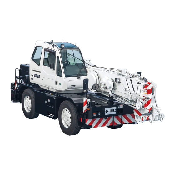
- Page 3 Foreword 2. External view The following is the traveling posture of the H-type outrigger specification machine. Front, rear, right, and left are the directions viewed from a position when operator sits on operator's seat with the boom directed to the front of the frame. Those directions remain invariant regardless of slewing direction of the superstructure.
- Page 4 Foreword 3. Outline of specifications Spec. No. GR-130E-2-00103 Item 2M2D (Australia) No. of boom sections No. of jib stages (base (jib 1), top (jib 2)) (Power tilt jib) Single top Fitted Main winch Fitted Auxiliary winch Fitted Winch high-speed hoisting down Fitted Winch Winch brake...
- Page 5 Foreword 4. Conversion table Length millimeter centimeter meter inch foot mile kilometer in, ” ft, ’ 1×10 1×10 3.93701×10 3.28084×10 1.60934 1×10 1×10 3.93701×10 3.28084×10 6.21373×10 1×10 1×10 3.93701×10 3.28084 2.54×10 2.54 2.54×10 8.33333×10 3.048×10 3.048×10 3.048×10 1.2×10 Speed km/h mile/h, mph 6.21373×10 1.60934...
- Page 6 Foreword Mass gram kilogram ounce pound metric ton short ton s. t 1×10 3.5274×10 2.20462×10 1×10 1.10231×10 1×10 3.5274×10 2.20462 1×10 1.10231×10 2.83495×10 2.8349×10 6.25×10 2.83495×10 3.12494×10 4.53592×10 4.53592×10 1.6×10 4.53592×10 5×10 1×10 1×10 3.5274×10 2.20462×10 1.10231 9.07185×10 9.07185×10 3.2×10 2×10 9.07185×10 Pressure...
- Page 7 Foreword 5. Drawing method of illustrations in this service manual The third angle projection method of mechanical drawing is used for the illustrations in this service manual. The third angle projection method is generally composed of the front view (the figure viewed from the front: A), top view (the figure viewed from the top: B), and right-side view (the figure viewed from the right: C) as shown below.
- Page 8 6. Group index Data, Adjustment and Checks System Diagrams WA04-5470E...
- Page 9 Foreword 7. Contents Spec. No. GR-130E-2-00103 Section 2M2D (Australia) Data, Adjustment and Checks Service Data Adjusting Pressure (Hydraulic Pressure) Adjusting Pressure (Pneumatic Pressure) Air Bleeding Procedure Adjusting Procedure (Electric) Assembly Adjustment (Crane Operation) Assembly Adjustment (Traveling Device) Operation Check (Crane Operation) Operation Check (Traveling Device) Inspection and Maintenance Y-10...
- Page 10 Foreword Spec. No. GR-130E-2-00103 Section 2M2D (Australia) Location of Installation Hydraulic Parts Location Diagram (Upper) Hydraulic Parts Location Diagram (Lower) Hydraulic Parts Location Diagram (Torque Converter) Pneumatic Parts Location Diagram Electric Parts Location Diagram (Upper) Z-10 Electric Parts Location Diagram (Lower) Z-11 Harness Diagrams Harness (Upper)
-
Page 11: Table Of Contents
Data, Adjustment and Checks Contents Y-1 Service Data ........1 Y-2 Adjusting Pressure (Hydraulic Pressure) ....12 Amounts of oil and coolant ......1 Location (position of relief valve etc.) ..12 Operating speed ........1 Items ............ 13 Hydraulic device ........2 Winch ............ - Page 12 Y-6 Assembly Adjustment Hydraulic motor assy ......26 (Crane Operation) ....36 Slewing motor ........... 26 Winch motor ..........26 Adjusting boom telescoping wire ropes ... 36 Air conditioner motor ........ 26 Adjusting the telescoping wire rope Winch counterbalance valve for the top and 5th boom sections ..
- Page 13 Y-8 Operation Check (Crane Operation) ....45 Outrigger status indicator ......45 Hoisting........... 45 ............ 46 Boom telescoping control ......47 Extension ..........47 Retraction ..........47 Emergency telescoping ......48 Warning ..........49 Eco mode operation check ..... 49 Y-9 Operation Check (Traveling Device) ....
-
Page 14: Service Data
Service Data Service Data [NOTICE] Standard values are values at time of vehicle shipment from TADANO. Limit values are the limits at which adjustment or part replacement is necessary. 1. Amounts of oil and coolant (1 L = 2.64172 × 10... -
Page 15: Hydraulic Device
Service Data 3. Hydraulic device 3.1 Hydraulic pump Item Standard value Remarks Speed reducing ratio 1.044 Idling (min 738 ± 19 Eng. 770 ± 20 Variable piston pump Max. (min 1628 ± 29 Eng. 1700 ± 30 (PTO - ON) Displacement (cm /rev) 45.8 + 45.8... -
Page 16: Hydraulic Cylinder
Service Data 3.3 Hydraulic cylinder [NOTICE] (1 m = 3.28084 ft) (1 mm = 3.93701 × 10 Keep the hydraulic oil temperature during the following inspections. Remarks Standard Item value Condition and method Safety and notice Inspection conditions 1. Boom angle: 60° ± 2° (Lowering operation) 2. - Page 17 Service Data Remarks Standard Item value Condition and method Safety and notice Inspection conditions 1. Angle lowered by 5° ± 2° from jib tilt upper limit (minimum jib offset angle) 2. Boom angle: 60° ± 2° 3. Engine stop 1° or less/ 4.
-
Page 18: Slewing Section
Service Data 4. Slewing section (1 mm = 3.93701 × 10 Item Standard value Remarks Horizontal play 3 mm or less Amount of slewing play Vertical play 1.2 mm or less 5. Boom section 5.1 Slide plate (1 mm = 3.93701 × 10 Replacement Standard standard... -
Page 19: Boom Bending And Deformation
Service Data 5.2 Boom bending and deformation (1 mm = 3.93701 × 10 Item Standard value (mm) Remarks Overall boom bending No significant vertical or horizontal Set the machine (at full extension, maximum elevation angle, with bends shall be found along the entire level. -
Page 20: Jib Bending And Deformation
Service Data 5.3 Jib bending and deformation (1 mm = 3.93701 × 10 Item Standard value (mm) Remarks Check for bending of the whole jib a ≤ 5.1 a ≤ 1.5 + L /1000 No significant bending in vertical and L = 3600 horizontal direction shall be found. -
Page 21: Sheave
Service Data 5.5 Sheave (1 mm = 3.93701 × 10 Standard of Limit of minor Item minor diameter diameter (mm) Remarks (mm) (*1) Determination of limit minor • Top boom upper diameter Φ192 Φ188.6 • Single top (When rope of nominal diameter •... -
Page 22: Criteria For Maintenance
Service Data 6. Criteria for maintenance and replacement of vehicle 6.1 Power transmission device Item Standard value Remarks Idling (min 770 ± 20 3000 ± 50 1700 ± 30 Eco mode: OFF 2480 ± 20 Speed limiter Max. (min (Reference value) Check conditions ・PTO switch: OFF When torque converter stalls... -
Page 23: Steering Device
Service Data 6.3 Steering device (1 mm = 3.93701 × 10 Item Standard value Remarks Cylinder side Φ25 –0.021 Pin outer diameter (mm) Rod side Φ25 –0.021 Clearance above and below axle (mm) 0.05 to 0.2 Camber (°) Caster (°) Kingpin angle (°) Toe-in (mm) Tire size... -
Page 24: Mass Table
Y-1 . Y-1 . Service Data 7. Mass table The dry weights of the major components are shown in the table below. Refer the weights, and select appropriate hoisting devices when removing and installing the component. Unit: kg (lb) Mass Assembly name Power Pin fixed... -
Page 25: Adjusting Pressure
Adjusting Pressure (Hydraulic Pressure) Adjusting Pressure (Hydraulic Pressure) 1. Location (position of relief valve etc.) WY02-2090E... -
Page 26: Items
Deactivate the stroke end slow stop function in the user mode of AML (after the pressure adjustment, make sure to activate the slow stop function). Oil temperature: 50 ± 5°C (122 ± 9°F) (Hydraulic oil: TADANO Hydraulic Oil LL) When not described to use the pressure check port, check the main pump pressure display on the AML display panel. - Page 27 Adjusting Pressure (Hydraulic Pressure) WY02-2090E...
-
Page 28: Elevating
Deactivate the stroke end slow stop function in the user mode of AML (after the pressure adjustment, make sure to activate the slow stop function). Oil temperature: 50 ± 5°C (122 ± 9°F) (Hydraulic oil: TADANO Hydraulic Oil LL) When not described to use the pressure check port, check the main pump pressure display on the AML display panel. -
Page 29: Slewing
Adjusting Pressure (Hydraulic Pressure) 2.3 Slewing [NOTICE] Oil temperature: 50 ± 5°C (122 ± 9°F) (Hydraulic oil: TADANO Hydraulic Oil LL) When not described to use the pressure check port, check the main pump pressure display on the AML display panel. -
Page 30: Outrigger
Adjusting Pressure (Hydraulic Pressure) 2.4 Outrigger [NOTICE] Oil temperature: 50 ± 5°C (122 ± 9°F) (Hydraulic oil: TADANO Hydraulic Oil LL) Shift the control lever or switch while the engine is idling, then increase engine speed. Engine Set pressure Item... -
Page 31: Remote Control Pilot Valve
Adjusting Pressure (Hydraulic Pressure) 2.5 Remote control pilot valve [NOTICE] Oil temperature: 50 ± 5°C (122 ± 9°F) (Hydraulic oil: TADANO Hydraulic Oil LL) Shift the control lever or switch while the engine is idling, then increase engine speed. Engine... -
Page 32: Steering
Adjusting Pressure (Hydraulic Pressure) 2.6 Steering [NOTICE] Oil temperature: 50 ± 5°C (122 ± 9°F) (Hydraulic oil: TADANO Hydraulic Oil LL) Shift the control lever or switch while the engine is idling, then increase engine speed. Engine Set pressure Item... -
Page 33: Torque Converter Oil Pressure
AML. 2.8 Hook-in [NOTICE] Oil temperature: 50 ± 5°C (122 ± 9°F) (Hydraulic oil: TADANO Hydraulic Oil LL) When not described to use the pressure check port, check the main pump pressure display on the AML display panel. -
Page 34: Jib Tilt
Adjusting Pressure (Hydraulic Pressure) 2.9 Jib tilt [NOTICE] Oil temperature: 50 ± 5°C (122 ± 9°F) (Hydraulic oil: TADANO Hydraulic Oil LL) When not described to use the pressure check port, check the main pump pressure display on the AML display panel. -
Page 35: (Pneumatic Pressure)
Y-3 . Y-3 . Adjusting Pressure (Pneumatic Pressure) Adjusting Pressure (Pneumatic Pressure) Set pressure No. in Item Remarks circuit kgf/cm diagram Turning on pressure 710 ± 20 7.2 ± 0.2 103 ± 3 Check that the air dryer Pressure recovers its performance regulator +0.3 Turning off pressure... -
Page 36: Air Bleeding Procedure
Air Bleeding Procedure Air Bleeding Procedure 1.2 Variable piston pump 1. Hydraulic pump 1. Fill the hydraulic oil tank with the hydraulic oil. (If the suction section is disassembled due to repair [NOTICE] or other reasons, bleed the suction side from the Be sure that the following conditions are met before air-bleed plug on the suction side as described starting the engine. -
Page 37: Variable Piston Pump (When The Tank Pressurization Tool Is Used)
Air Bleeding Procedure 1.3 Variable piston pump (when the tank 6. If any abnormality is found, bleed the hydraulic pressurization tool is used) pump again. [NOTICE] 7. If there is no abnormal noise, turn ON the PTO Adjust the pressure setting of the tank pressurization tool to 15 kPa (0.15 kgf/cm²) (2.2 psi). -
Page 38: Winch Brake
Air Bleeding Procedure 2. Winch brake 3. Service brake [NOTICE] [NOTICE] When winding or unwinding the winch, pay attention The vehicle has two boosters; one for the front to the hook position. wheel brakes and the other for the rear wheel brakes. -
Page 39: Hydraulic Motor Assy
Air Bleeding Procedure 4.2 Winch motor 4. Hydraulic motor assy [NOTICE] 4.1 Slewing motor Do not apply any load to the motor before completing air bleeding. [NOTICE] Do not apply any load to the motor before Bleed the winch motor by following either (1) or (2). completing air bleeding. -
Page 40: Winch Counterbalance Valve
Air Bleeding Procedure 5. Winch counterbalance valve 6. Slewing control valve (main and auxiliary) (back-pressure valve) [NOTICE] [NOTICE] Conditions For the main and auxiliary winch, bleed the Engine speed : Max. (1700 min counterbalance valves as follows: : ON Slewing brake : ON 1. -
Page 41: Pilot Circuit
Air Bleeding Procedure 7. Pilot circuit 4 Winch (main and auxiliary) (hydraulic pilot control valve) Pull out the connector (CN100) of the AML vent [NOTICE] solenoid valve. Conditions Move the winch lever fully to the hoisting up side. Engine speed : idling (770 min : ON Keep the above conditions for 20 seconds or... -
Page 42: Hydraulic Valve (Winch Brake)
Y-4 . Y-4 . Air Bleeding Procedure 8. Hydraulic valve (winch brake) [NOTICE] Bleed this valve after the pilot circuit (hydraulic pilot control valve) (See the section 7.) is bled. Conditions Engine speed : Idling (770 min : ON 1. Open the air-bleed plug and move the winch lever fully to the end of its stroke in the direction corresponding to the plug. -
Page 43: Adjusting Procedure (Electric)
Adjusting Procedure (Electric) Adjusting Procedure 2. 4th/top boom full retraction detection (Electric) switch (CN859) Adjust the switch position so that its contact is 1. 2nd/3rd boom full retraction detection shifted (opened/closed) when the top boom switch (CN553) section is extended/retracted to the position where it is 5 to 8 mm (0.2 to 0.31 in) longer than its fully 1. -
Page 44: Jib Lock Pin Detection Switch (Cn572)
Adjusting Procedure (Electric) 3. Jib lock pin detection switch (CN572) 1. Apply thread locking agent (ThreeBond 1401 or equivalent) to the threaded section of the detector switch. 2. Stow the jib. 3. Adjust the clearance from the detector switch and fix the switch using nuts. -
Page 45: Jib Connection Pin
Adjusting Procedure (Electric) 4. Jib connection pin detection switch 4. Make sure that the detector switch works when (CN549) the connection pin is inserted. 1. Change the installing position of the detector Switch fixing bolt tightening torque: switch roller lever as shown in the figure below. 4.9 to 5.9 N-m (50 to 60 kgf-cm) (3.6 to 4.3 ft-lbf) 2. -
Page 46: Detection Switch (Cn549)
Adjusting Procedure (Electric) 5. Main winch drum rotation detection 6. Aux. winch drum rotation detection switch (CN591) switch (CN592) 1. Apply thread locking agent (ThreeBond 1401 or 1. Apply thread locking agent (ThreeBond 1401 or equivalent) to the threaded section of the equivalent) to the threaded section of the detection switch. -
Page 47: Over-Front Detection Switch (Cn521)
Adjusting Procedure (Electric) 7. Over-front detection switch (CN521) 1. Apply the thread locking agent (ThreeBond 1401 or equivalent) on the thread section of switch. 2. Fully retract the boom and slewing it to the over-front. 3. Adjust the clearance between the detection side of the switch and the dog. -
Page 48: Detection Switch (Cn408)
Y-5 . Y-5 . Adjusting Procedure (Electric) 8. Straight ahead detection switch 9. Rear steering lock pin (IN) detection (CN408) switch (CN417), (OUT) detection switch (CN418) 1. Apply thread locking agent (ThreeBond 1401 or equivalent) to the switch screw threads Adjust the vertical position of the lock pin (IN) beforehand. -
Page 49: (Crane Operation)
Assembly Adjustment (Crane Operation) Assembly Adjustment (Crane Operation) 1. Adjusting boom telescoping wire ropes 1.1 Adjusting the telescoping wire rope for the top and 5th boom sections 1. With the boom fully retracted, tighten adjustment nut A for the top boom section retraction wire rope. Tightening torque: 39.2 N-m (400 kgf-cm) (28.9 ft-lbf) For retracting top boom section 2. - Page 50 Assembly Adjustment (Crane Operation) 3. Evenly tighten the adjustment nuts C (2 points) at the threaded end of the top boom section extension wire rope until the top boom section is slightly (1 to 5 mm (0.04 to 0.2 in)) away from the 5th boom section. For extending top boom section /retracting 5th boom section WY05-5150E...
- Page 51 Assembly Adjustment (Crane Operation) 4. Tighten adjustment nut A of the top boom section retraction wire rope until the top and 5th boom sections are blocked by their respective stoppers (the boom sections are fully retracted). 5. Extend the boom by 200 to 300 mm (0.656 to 0.984 ft), then retract it all the way to complete adjustment. If the boom is not fully retracted, follow the below procedure to check and adjust it.
-
Page 52: Adjusting The Telescoping Wire Rope For The 3Rd Boom Section
Y-6 . Y-6 . Assembly Adjustment (Crane Operation) 1.2 Adjusting the telescoping wire rope for the 3rd boom section 1. Fully retract the boom, then loosen the 3rd boom section extension wire rope. 2. Evenly tighten adjustment nuts D at the threaded 3. -
Page 53: (Traveling Device)
Assembly Adjustment (Traveling Device) Assembly Adjustment (Traveling Device) 1. Service brake adjustment 1.1 Adjusting the brake pedal With the pedal weight causing roller to contact the plunger, adjust the bolt until it contacts the stopper, then use the nut to lock it in place. 1.2 Check after replacing brake hose After you replace the brake hoses and so on, make sure that any contact does not occur... -
Page 54: Accelerator Adjustment
Assembly Adjustment (Traveling Device) 2. Accelerator adjustment 2.1 Accelerator pedal 1. Adjust bolt F so that lever I is vertical, then lock the bolt with the nut. 2. Move the accelerator sensor lever so that it contacts stopper C. Then adjust nut H until there is no pedal play. -
Page 55: Parking Brake Adjustment
Assembly Adjustment (Traveling Device) 3. Parking brake adjustment 4. Tire and steering angle adjustment 3.1 Adjusting the clearance 4.1 Tire air pressure (between brake shoe and drum) Tire size 275/80 R22.5 315/80 R22.5 1. Jack up the crane and keep the parking brake +100 +100 lever disengaged by removing the connecting pin. -
Page 56: Adjusting The Steering Angle
Assembly Adjustment (Traveling Device) 4.2 Adjusting the steering angle 5. Engine speed (and governor setting) [NOTICE] Before checking the engine speed, run the engine to warm it up. (Torque converter oil temperature should reach approximately 50°C (122°F).) 1. No-load Max. speed •... -
Page 57: Torque Converter And Transmission
Y-7 . Y-7 . Assembly Adjustment (Traveling Device) 6. Torque converter and transmission 7. Camera mounting angle adjustment Adjust the camera mounting angle so that the 6.1 Maximum allowable speed mirror in the camera image is located as shown in Units: km/h (mph) the figure below. -
Page 58: Operation Check
Operation Check (Crane Operation) Operation Check 2. Hoisting (Crane Operation) [Condition] • Load : None 1. Outrigger status indicator • Engine speed : Approximately 770 min to medium speed [Procedure] Main switch : ON Shift lever : Not in N position Move the telescoping lever all the way to the end of its stroke. -
Page 59: Jib
Operation Check (Crane Operation) 3. Jib 1. Automatic stop by two-blocking must not occur while the jib set status is registered. 2. Check the pin A insertion. • When the set pin is removed from part B, the icon must appear. •... -
Page 60: Boom Telescoping Control
Operation Check (Crane Operation) 4.2 Retraction 4. Boom telescoping control Approximately 16.4 m (53.8 ft) boom [Boom length: 5.3 - 23.8 m (17.4 - 78 ft)] (4th shortest) CN503: 4th/top boom emergency telescoping switch CN504: 2nd/3rd boom emergency telescoping switch CN506: 4th/top boom extending switch 4th to top boom retract. -
Page 61: Emergency Telescoping
Operation Check (Crane Operation) 4.3 Emergency telescoping 5.3 m (17.4 ft) boom (base) Turn the AML emergency switch to the emergency side. 1. With CN503 switch pressed, extend the 4th, 5th, and top boom by approximately 1 m (3.3 ft) each. At this time, AML displays an error code immediately after boom extension starts. -
Page 62: Warning
Y-8 . Y-8 . Operation Check (Crane Operation) 5. Warning [NOTICE] For the location of the buzzers, refer to "Z-10 Electric Parts Location Diagram (Upper), 1. Inside cab ". Warning Item Sound Checking procedure buzzer Buzzer sounds at 100% when main switch is ON and PTO Buzzer Continuous beep AML limit... -
Page 63: Operation Check
Operation Check (Traveling Device) Operation Check 2. Automatic transmission (Traveling Device) (1 km/h = 0.6214 mph) [NOTICE] 1. Exhaust brake Numbers indicate speedometer readings. (units: km/h) [NOTICE] ( ) Indicates lock up ON and OFF values. Jack up the crane and make sure the crane is set * Indicates downshift points when the up horizontally and all tires are off the ground. -
Page 64: Rear Steering Lock
Operation Check (Traveling Device) 3. Rear steering lock 3.1 Operation check A Turn the rear steering lock switch to "Release". (The indicator turns on.) Release The indicator is on. The indicator is off. Lock IWY05-0141E15 Check that the indicator is on. Switch to 4-wheel, crab, or rear steering. -
Page 65: Operation Check B
Operation Check (Traveling Device) 3.2 Operation check B 4. Overshift prevention (1 km/h = 0.6214 mph) 1. With the lock pin engaged, upshift to 2nd gear. Check that the lock pin does not disengage even [NOTICE] when the rear steering lock switch is turned to Jack up the vehicle and shift to 4WD High position. -
Page 66: Warning
Operation Check (Traveling Device) 5. Warning [NOTICE] For the location of the buzzer, refer to "Z-10 Electric Parts Location Diagram (Upper), 1. Inside cab". Warning Item Sound Check conditions buzzer Buzzer sounds when the following conditions are met. Total air low 1. -
Page 67: Suspension Lock
Y-9 . Y-9 . Operation Check (Traveling Device) 6. Suspension lock 7. Speedometer (1 km/h = 0.6214 mph) [NOTICE] Conditions When the actual traveling speed of the vehicle is V Crane status : On-rubber, boom directed forward the reading of the speedometer (V ) shall meet the Shift lever : N position. -
Page 68: Inspection And Maintenance
Y-1 0 . Y-1 0 . Inspection and Maintenance Y-10 Inspection and Maintenance 1. Refer to “Inspection and Maintenance” in “Operation Manual” of its applicable crane. 2. Maintenance of line filter Maintenance table Inspection and maintenance Parts interval Parts name (used) Type of work Points/Quantity 1200h... -
Page 69: Thread Size Table
Y-1 1 . Y-1 1 . Boom Connecting Pin and Thread Size Table Y-11 Boom Connecting Pin and Thread Size Table (Note): “ ” means that more than one spec. No. are applicable. (Unit: mm) (1 mm = 0.039 inch) GR-130E-2- Applicable spec. - Page 70 System Diagrams Contents Z-1 Hydraulic Circuit ......1 Electric circuit (engine start) ....13 Comparison table of hydraulic parts Z-6 Hydraulic Parts Location Diagram (part No., part name, (Upper) ........14 coordinate and location) ....1 Hydraulic circuit diagram ......2 Unit ............
- Page 71 Z-7 Hydraulic Parts Location Diagram AML external indicator lamp (3 colors) (Lower) ........24 (option) ........42 Suction ........... 24 AML parts assy........43 Steering ..........25 Length and angle indicator assy ....44 Outrigger (H type) ........26 Boom head and jib angle detector ... 45 Center joint ..........
- Page 72 Harness (two-blocking) ......64 10. Harness (jib 1) ........65 11. Harness (SCT) ........66 Z-13 Harness (Lower) ......67 Harness (lower main) ......67 Comparison table (connector No., usage and coordinate) ....... 67 Harness (main) ......... 68 Harness (air) ........... 69 Harness (electronic governor) ....
-
Page 73: Hydraulic Circuit
Hydraulic Circuit “Location” shows each applicable paragraph No. of this manual’s contents. Hydraulic Circuit Refer to the contents. 1. Comparison table of hydraulic parts (part No., part name, coordinate and location) Hydraulic Hydraulic Hydraulic Part No. Part name circuit Location Part No. -
Page 74: Hydraulic Circuit Diagram
Z-1. Z-1. Z-1. Hydraulic Circuit 2. Hydraulic circuit diagram [NOTICE] · Suspension lock cylinder codes (FL), (FR), (RL) and (RR) indicate each installation location of the cylinder. · Outrigger solenoid valve codes (FL), (FR), (RL) and (RR) indicate each installation location of the valve. ·... -
Page 75: Torque Converter Circuit
Z- 2. Z- 2. Z- 2. Torque Converter Circuit Z-2 Torque Converter Circuit (Parts, location: refer to Z-8) Thermo sensor (T/C oil temp.) (CN427) Sensor Torque converter case Transmission case Lubricating relief valve Oil cooler M16×1.5 G3/4 Accumulator G3/4 G1/2 Torque converter inlet Sensor relief valve... -
Page 76: Pneumatic Circuit
Z- 3. Z- 3. Z- 3. Pneumatic Circuit Z-3 Pneumatic Circuit Air pressure switch (stop lamp) SL55 (contact close: depressing brake pedal) (1L=2.64172×10 gal) (Parts, location: refer to Z-9) Air solenoid valve Operating pressure: 29 (auxiliary operating brake) +0.2 (0.3 kgf/cm ) (4.2 psi) - Page 77 CN506 4th/top boom extending switch (ISO array) CN850 Washer motor (front) D-11 CN639 MDT (for maintenance) G-15 CN507 4th/top boom extending switch (TADANO array) CN852A CN640 AML connector (CN1) Flood lamp (slewing table left) Z-12 3. CN509 PTO switch O-11...
- Page 78 Electric Circuit (Upper) (Note): △ Applicable serial No. : FD3398-- The connector with “#” is not applied to this machine. Electric Electric Harness Harness CN No. Usage circuit CN No. Usage circuit diagram diagram coordinate coordinate CN874 Fuse box (right) P-14 CN1330 MDT reset switch M-12...
-
Page 79: Electric Circuit (Upper)
Electric Circuit (Upper) 2. Reading method of electric circuit diagram 2. Indication of wiring diameter ■Conditions Specify the wiring thickness of thick cable 1. Crane : traveling condition (preferably more than 1.25). 2. PTO switch : OFF 3. Boom : fully retracted, over-front 4. - Page 80 (730MZ) R/W (B30KK) B (153AA) L/G Flood lamp(the top of Cab) (B30JK) B (035KB) BR 0.85LG O-13(CN871) Wiring built-in cab Roof washer switch (TADANO array) O-7(CN803) 2-2-2 Di22+ High-speed lowering input(SUB) (035KA) BR (157KJ) R/G (186AA) L/B (B30JJ) B (378AA) B/L (157KL) R/G 0.85LO...
- Page 81 (730MZ) R/W (B30KK) B (153AA) L/G Flood lamp(the top of Cab) (B30JK) B (035KB) BR 0.85LG O-13(CN871) Wiring built-in cab Roof washer switch (TADANO array) O-7(CN803) 2-2-2 Di22+ High-speed lowering input(SUB) (035KA) BR (157KJ) R/G (186AA) L/B (B30JJ) B (378AA) B/L (157KL) R/G 0.85LO...
-
Page 82: Comparison Table (Connector No., Usage, Coordinate And Harness Diagram)
Electric Circuit (Lower) “Harness diagram” shows applicable paragraph No. of this manual’s contents. Electric Circuit (Lower) Refer to the contents. 1. Comparison table (connector No., usage, coordinate and harness diagram) Electric Electric Electric Harness Harness Harness CN No. Usage circuit CN No. -
Page 83: Electric Circuit (Lower
Electric Circuit (Lower) Electric Harness CN No. Usage circuit diagram coordinate CN1080 Spare connector C-17 CN1088 Lower transmitter (STM-E) (for K-LINE connection) A-15 Z-13 3. CN1089 MUT-3 (for K-LINE connection) CN1091 Maintenance connector B-14 Engine start CN1115 Z-13 5. (Refer to “3. Electric circuit (lower, engine start)”.) CN1630A Emergency head lamp M-13... - Page 84 Electric Circuit (Lower) 2. Electric circuit (main) Lower transmitter (STM-E) [NOTICE] Transmission (for K-LINE connection) MDT-9R-L Lower MDT MUT-3 CN1088 1. (CN***) and (R***) indicate whether the connector are used depending on the AMP040mk1 CN604 CN421 (for K-LINE connection) CN1003 CAN terminating resistance (120Ω) (S05-W) W (S05-W) W...
-
Page 85: Electric Circuit (Engine Start)
Z- 5. Z- 5. Z- 5. Torque Converter Circuit 3. Electric circuit (engine start) (RA22) (CN766) 1 4 2 1 4 2 1 4 2 1 4 2 (615AA) Emergency accelerator signal: Slip ring 15 Engine emergency Starter continuous Glow relay ECU main power stop relay energization prevention... -
Page 86: Hydraulic Parts Location Diagram
Hydraulic Parts Location Diagram (Upper) Z-6 Hydraulic Parts Location Diagram (Upper) 1. Unit SL120 SL125 FRONT SL124 SL121 33-1 33-2 IWZ07-363001E WZ07-4370E... - Page 87 Hydraulic Parts Location Diagram (Upper) Detail 36-1, 36-2, 37 (37-1, 37-2, 37-3, 37-4), 38-1, 39, 58, 59 Detail A 36-2 36-1 38-1 37-3 37-4 37-1 SL101 37-2 SL100 Detail C Detail B IWZ07-363002E WZ07-4370E...
- Page 88 Hydraulic Parts Location Diagram (Upper) Detail 35-5, 57, 79-1, 81, 82, 83 35-5 SL160 SL102 79-1 Detail D Detail E Detail G Detail F IWZ07-4370E01 343-455-91000 WZ07-4370E...
-
Page 89: Winch
Hydraulic Parts Location Diagram (Upper) 2. Winch Detail 60-1, 60-2, 60-3, 60-4 60-2 60-4 60-1 60-3 FRONT IWZ07-363004E 342-220-90000 Detail 35-4, 72, 79-2 FRONT SL260 SL261 79-2 35-4 IWZ07-4370E02 343-455-92501 WZ07-4370E... -
Page 90: Telescoping
Hydraulic Parts Location Diagram (Upper) 3. Telescoping 53-2 No.2 No.1 53-1 IWZ07-233003a 343-455-96000 342-109-10000 4. Elevation 38-3 38-2 IWZ07-4370E03 343-441-43500 342-410-60000 360-280-60000 WZ07-4370E 343-634-01000... -
Page 91: Slewing
Hydraulic Parts Location Diagram (Upper) 5. Slewing FRONT IWZ07-363005E 343-455-93000 343-006-90000 WZ07-4370E... -
Page 92: Return
Hydraulic Parts Location Diagram (Upper) 6. Return FRONT IWZ07-363006E 343-461-74500 7. Drain FRONT 36-3 IWZ07-363007E 343-461-75000 WZ07-4370E... -
Page 93: Steering
Hydraulic Parts Location Diagram (Upper) 8. Steering IWZ07-363008 347-220-41000 347-223-33001 9. Air conditioner IWZ07-233009 345-113-61000 WZ07-4370E... -
Page 94: Operation Assy, Operation Valve
Hydraulic Parts Location Diagram (Upper) 10. Operation assy, operation valve [ ] indicate TADANO layout on Remote control valve arrangement. 35-2 Slewing Telescoping/jib tilt [Elevation] Slewing Telescoping/jib tilt [Elevation] Telescoping/jib tilt [Elevation] Aux. winch [Telescoping/jib tilt] Aux. winch [Telescoping/jib tilt] Aux. -
Page 95: Jib (Boom)
Z-6. Z-6. Hydraulic Parts Location Diagram (Upper) 12. Jib (boom) 35-6 IWZ07-4370E05 343-455-82000 13. Jib 35-7 IWZ07-4370E06 343-455-81000 342-218-42000 360-539-40000 WZ07-4370E... -
Page 96: Hydraulic Parts Location Diagram (Lower
Hydraulic Parts Location Diagram (Lower) Z-7 Hydraulic Parts Location Diagram (Lower) 1. Suction Detail A FRONT IWZ07-4380E01 346-413-71000 WZ07-4380E... -
Page 97: Steering
Hydraulic Parts Location Diagram (Lower) 2. Steering Rear side 22-4 FRONT 21-4 22-3 27-4 21-3 27-3 22-2 FRONT 21-2 27-2 21-1 22-1 27-1 Front side SL33 SL31 (26) (25) SL03 SL02 SL30 35-1 Detail A IWZ07-4380E02 346-413-72000 WZ07-4380E... -
Page 98: Outrigger (H Type)
Hydraulic Parts Location Diagram (Lower) 3. Outrigger (H type) FRONT SL26 09-3 SL27 Detail C SL22 09-1 SL23 Detail A SL29 09-4 SL28 Detail D SL25 09-2 SL24 Detail B IWZ07-364004E 346-414-43000 WZ07-4380E... -
Page 99: Center Joint
Hydraulic Parts Location Diagram (Lower) 4. Center joint FRONT SL06 SL20 SL04 SL21 IWZ07-364005E 346-416-34000 WZ07-4380E... -
Page 100: Return
Hydraulic Parts Location Diagram (Lower) 5. Return FRONT Detail A IWZ07-4380E03 346-416-35000 WZ07-4380E 346-413-75500... -
Page 101: Outrigger Main Body (H Type)
Z-7. Z-7. Hydraulic Parts Location Diagram (Lower) 6. Outrigger main body (H type) FL: 11-1 FR: 11-2 RL: 11-3 RR: 11-4 FL: 10-1 FR: 10-2 RL: 10-3 RR: 10-4 FR: 12-2 RR: 12-4 FL: 12-1 RL: 12-3 IWZ07-4380E04 346-110-40000 WZ07-4380E 346-115-90000... -
Page 102: Hydraulic Parts Location Diagram (Torque Converter)
Z-8. Z-8. Hydraulic Parts Location Diagram (Torque Converter) Z-8 Hydraulic Parts Location Diagram (Torque Converter) 1. Torque converter related Upper (SOL A) 179 Middle (SOL B) 178 Lower (SOL C) 180 SL41 (PTO) SL49 (Lock up) IWZ07-4390E01 349-224-10000 WZ07-4390E... -
Page 103: Pneumatic Parts Location
Pneumatic Parts Location Diagram Z-9 Pneumatic Parts Location Diagram 1. Service brake related (upper) FRONT SL55 IWZ08-0660E01 347-223-20000 WZ08-0660E... -
Page 104: Service Brake Related (Lower)
Pneumatic Parts Location Diagram 2. Service brake related (lower) FRONT SL54 SL50 Detail B Rear Front Detail A IWZ08-0660E02 WZ08-0660E 349-229-30000... -
Page 105: Control Parts (Lower)
Z-9. Pneumatic Parts Location Diagram Z-9. 3. Control parts (lower) FRONT (delivery section) SL57 (transmission section) SL51 Detail B 161,162,163 Detail A IWZ08-0660E03 WZ08-0660E 349-229-20000... -
Page 106: Inside Cab
CN461 Boom raising detection switch: CN536 Boom lowering detection switch: CN537 CN834 Combination switch CN511, CN562 4th/top boom extending switch (TADANO array): CN507 Flasher unit Idling adjustment switch Cab floor plate Wiring built in cab CN814 (room lamp, roof wiper motor,... -
Page 107: Fd3398
CN461 Boom raising detection switch: CN536 Boom lowering detection switch: CN537 CN834 Combination switch CN511, CN562 4th/top boom extending switch (TADANO array): CN507 Flasher unit Idling adjustment switch Cab floor plate Wiring built in cab CN814 (room lamp, roof wiper motor,... -
Page 108: Horn Relay Assy
Z-10 Electric Parts Location Diagram (Upper) Z-10 1.2 Horn relay assy Horn relay Condenser (horn) CN972 CN973 To “harness (main)” CN974 Harness (horn relay) To ”harness (horn)” CN060 IWZ02-7530E03 343-528-01600 WZ02-7530E... -
Page 109: Horn Assy
Z-10 Electric Parts Location Diagram (Upper) Z-10 1.3 Horn assy To ”harness (horn relay)” CN060 Harness (horn) Horn (low) CN971 Horn (high) High CN970 IWZ02-7530E04 343-528-02100 WZ02-7530E... -
Page 110: Relay Assy
Z-10 Z-10 Z-10 Electric Parts Location Diagram (Upper) 2. Relay assy 2.1 --FD3397 Fuse box (center) b-contact (CN875, CN876, CN877, CN878, CN879) (Normal close type relay) a-contact c-contact Fuse box (left) Fuse box (right) (Normal open type relay) (Combination type relay) (CN868, CN869) (CN870, CN871, CN872, CN873, CN874) Spare... - Page 111 Z-10 Z-10 Z-10 Electric Parts Location Diagram (Upper) 2.2 FD3398-- Fuse box (center) (CN875, CN876, CN877, CN878, CN879) c-contact Fuse box (left) Fuse box (right) (Combination type relay) (CN868, CN869) (CN870, CN871, CN872, CN873, CN874) Slotted hole side Spare Spare Spare Spare RC16...
-
Page 112: Slewing Table, Boom
Z-10 Z-10 Z-10 Electric Parts Location Diagram (Upper) 3. Slewing table, boom Aux. winch high-speed hoisting down selection solenoid valve (SL261) CN261 Jib connection pin detection switch Main winch high-speed hoisting down selection solenoid valve (SL260) CN549 CN260 2nd/3rd boom full retraction detection switch CN553 Drum rotation detection switch (main winch) CN591... -
Page 113: Pressure Switch Installation Diagram
Z-10 Z-10 Z-10 Electric Parts Location Diagram (Upper) 4. Pressure switch installation diagram [ ] indicate TADANO layout on Remote control valve arrangement. Switch operating list Slewing left detection switch Lever operation CN541 Note Switch name Boom lowering detection switch... -
Page 114: Aml External Indicator Lamp (3 Colors)
Z- 10 Z- 10 Electric Parts Location Diagram (Upper) Z- 10 external indicator lamp (3 colors) (option) 5. AML AML external indicator lamp (3 colors) (option) FRONT CN827, CN828, CN829, CN830, CN1014 Harness (main) AML external indicator lamp (3 colors) (option) Yellow Green Slewing center... -
Page 115: Aml Parts Assy
Z-10 Z-10 Z-10 Electric Parts Location Diagram (Upper) 6. AML parts assy Pressure sensor (main pressure) CN581 To “harness (main)” CN899 Harness (AML) AML connector CN643, CN644, CN647 Boom top cord reel (AML side) CN579 Boom length and angle detector CN576 White tape To “harness (main)”... -
Page 116: Length And Angle Indicator Assy
Z-10 Z-10 Z-10 Electric Parts Location Diagram (Upper) 7. Length and angle indicator assy Boom length detector Harness (two-blocking) CN576 CN859 Boom angle detector CN553 4th/top boom full retraction detection switch CN859 View A 2nd/3rd boom full retraction detection switch CN553 Detail B IWZ02-440002Eb... -
Page 117: Boom Head And Jib Angle Detector
Z-10 Z-10 Z-10 Electric Parts Location Diagram (Upper) 8. Boom head and jib angle detector Transmitter (STM-D) (jib) CN672, CN673 Harness (boom head) Boom top cord reel (STM-D side) CN671 Cable (jib angle detector) Jib angle detector CN1063 Boom top cord reel (AML side) CN579 To “cable (jib angle detector)”... - Page 118 Z-10 Z-10 Z-10 Electric Parts Location Diagram (Upper) 9. Two-blocking Boom SW Boom length detector Single top SW Boom SW Boom length detector CN900 CN862 CN901 Harness (two-blocking) Connector CN948 Jib 1 CN900, CN901 1.25B Upside 1.25Y CN902 Two-blocking detection switch (boom) Harness (jib 1) 1.25B 1.25Y...
-
Page 119: Sct
Z-10. Z-10. Z-10. Electric Parts Location Diagram (Upper) 10. SCT CN1065 CN1066 Harness (SCT) GPS antenna Harness (main) CN1068 SCT (Satellite Antenna (for satellite communications) communications terminal) CN1070 For maintenance terminal (Dr. T) Controller GPS antenna CN1067 Connector (for satellite communications) Antenna cable Parts connection detail View B... -
Page 120: Lower, Main
Z-11 Z-11 Z-11 Electric Parts Location Diagram (Lower) Z-11. Electric Parts Location Diagram (Lower) 1. Lower, main Centralized greasing switch Backup buzzer CN431, CN432, CN433 CN751 Centralized greasing indicator CN735 Rear steering lock pin (OUT) detection switch: CN418 Rear steering lock pin (IN) detection switch: CN417 To harness (sub) To Fuel filter Side turn signal (R) - Page 121 Z-11 Z-11 Z-11 Electric Parts Location Diagram (Lower) 2. Lower electric unit box (MDT, relay assy) ECU DIAG lamp 1 (red) CN731, CN732 Controller RA11 RA32 (MDT) ECU DIAG lamp 2 (orange) CN733, CN734 RA15 RA16 RA17 RA21 Terminal base c-contact RA28 RA33...
-
Page 122: Relay And Fuse Box (Under The Battery)
Z-11. Z-11. Z-11. Electric Parts Location Diagram (Lower) Fuse box (upper) CN776, CN777 3. Relay and fuse box (under the battery) CN708 CN707 CN706 Fuse box (left) Fuse box (right) Location Fuse code Note Location Fuse code Note Head lamp relay CN766 7 5 A RA22... -
Page 123: Harness (Upper)
Loudspeaker (option) CN885 CN506 4th/top boom extending switch (ISO array) CN804 Room lamp CN887 To “harness (boom bottom)” CN507 4th/top boom extending switch (TADANO array) J-11 CN805 Level (illumination) B-11 CN891 To “harness (slewing table right)” CN509 PTO switch A-16... - Page 124 Z-1 2 Harness (Upper) Z-1 2 Harness CN No. Usage diagram coordinate Emergency operation relay Flood lamp relay (1) Flood lamp relay (2) Washer relay (roof wiper) Neutral starter relay Turn signal relay (right) Turn signal relay (left) #RA25 Air compressor stop relay RA26 Washer relay (front) RA30...
- Page 125 016AA 615AA To “harness (SCT)” 010AA 009AA 008AA To “harness (horn relay)” CN1070 4th/top boom extending switch CN532 S22A-W S22A-B 558AC CN974 (TADANO array) 004AA 022AB 021AA 020JR CN507 614AA 013AA 012AA SHIELD12 CN1023 261AA 328RP Slewing horn switch 178AA...
- Page 126 016AA 615AA To “harness (horn relay)” To harness “ICF” CN1070 010AA 009AA 008AA 4th/top boom extending switch CN532 S22A-W S22A-B 558AC CN974 (TADANO array) 004AA 022AB 021AA 020JR CN507 SHIELD12 614AA 013AA 012AA CN1023 261AA 328RP Slewing horn switch 178AA...
-
Page 127: Harness (Horn)
Z-12 Z-12 Harness (Upper) 1.3 Harness (horn) CN970B Horn (high) To “harness (horn relay)” CN970A CN060 CN971A Horn (low) CN971B IWZ04-5760E03 WZ04-5760E 343-528-02110... -
Page 128: Harness (Horn Relay)
Z-12 Z-12 Harness (Upper) 1.4 Harness (horn relay) Condenser (horn) CN973 Horn relay To “harness (main)” CN972 CN974 To “harness (horn)” CN060 IWZ04-5760E04 WZ04-5760E 343-528-01610... -
Page 129: Harness (Slewing Table, Right)
Z- 12 Z- 12 Harness (Upper) Z- 12 2. Harness (slewing table, right) To “harness (slewing warning lamp)” or Connector (for slewing warning lamp) CN920 403RF B03AB Ground (slewing table left) B03AA E003 To “harness (main)” CN891 CN100 283AA 273AA 282AA 272AA 281AA 271AA... -
Page 130: Harness (Slewing Table, Left)
Z- 12 Z- 12 Harness (Upper) Z- 12 3. Harness (slewing table, left) Main winch high-speed Aux. winch high-speed hoisting down selection hoisting down selection solenoid valve (SL260) solenoid valve (SL261) CN260 CN261 726AA B30TK 736AA B30TL N007 CN852A 174RC Flood lamp (slewing table left) CN854 CN852B... -
Page 131: Harness (Boom Bottom)
Z- 12 Z- 12 Harness (Upper) Z- 12 4. Harness (boom bottom) CN220 CN553 CN858 CN572 Telescoping/jib selection 2nd/3rd boom Cord reel (for boom length detector) Jib lock pin detection switch solenoid valve (SL220) full retraction detection switch 304AA 818AA 329AB B30TC 278AA 305AA... -
Page 132: Harness (Slewing Warning Lamp)
Z-12 Z-12 Harness (Upper) 5. Harness (slewing warning lamp) CN848B 1300 Slewing warning lamp (right) CN920 Vinyl (Ø05×Ø06) CN848A CN847B 1500 Slewing warning lamp (left) To “harness (slewing table right)” Vinyl (Ø05×Ø06) CN847A IWZ04-5760E08 WZ04-5760E 343-528-12040... -
Page 133: Harness (Aml)
Z- 12 Z- 12 Harness (Upper) Z- 12 6. Harness (AML) COTØ07 3850 1820 CN584 Pressure sensor (elevating cylinder, boom raising) (1150) S03-R2 S03-B2 S03-W Yellow tape Yellow tape SHIELD2 COTØ07 S01B-S 3850 2070 CN585 SHIELD4 (1400) Pressure sensor (elevating cylinder, boom lowering) S02A-S SHIELD5 S04-R... -
Page 134: Harness (Boom Head)
Z- 12 Z- 12 Harness (Upper) Z- 12 7. Harness (boom head) *1 B27AA B , B27AB B E027 Ground CN672 CN673 (STM-D) *1 B26AA B , B26AB B Transmitter (STM-D) (jib) Transmitter (STM-D) (jib) E026 Ground 395AA Plug Plug Plug Plug Plug... -
Page 135: Cable (Jib Angle Detector)
Z-12 Z-12 Harness (Upper) 8. Cable (jib angle detector) To “harness (boom head)” Jib angle detector CN578 CN1063 (65.5) 4000 SHIELD IWZ04-5760E11 WZ04-5760E 343-634-03200... - Page 136 Z- 12 Z- 12 Harness (Upper) Z- 12 9. Harness (two-blocking) Two-blocking 4th/top boom detection switch full retraction detection switch Roll with tape. (boom) CN859 CN862 1.25LG/B 1.25LG/B LG/B 0.75W 1.25Y LG/B Ø4×Ø6 Length 180 Vinyl tube 1.25B Ø6×Ø8 Length 620 Vinyl tube Ø4×Ø6 Length 460 Vinyl tube...
- Page 137 Z- 12 Z- 12 Harness (Upper) Z- 12 10. Harness (jib 1) CN948 CN900 CN901 Harness (Jib 1) connection diagram To “harness (two-blocking)” CN900 Connector (CN948) CN901 CN948 To “harness (two-blocking)” IWZ04-5760E13 WZ04-5760E 343-722-40100...
-
Page 138: Harness (Sct)
Z- 12. Z- 12. Harness (Upper) Z- 12. 11. Harness (SCT) 006AA 006AB 826AA S11-006 N004 016AB 558AC S11-005 B51AA B51AC CN1065 831AA 830AA 821AA 822AA N002 B51AD 834AA 833AA 832AA CN1066 CN1067 For maintenance terminal (Dr. T) 558AC S11-005 S11-006 N001 831AA... -
Page 139: Harness (Lower Main)
Z-1 3 Harness (Lower) Z-1 3 Z-1 3 Z-13 Harness (Lower) 1. Harness (lower main) 1.1 Comparison table (connector No., usage and coordinate) Harness Harness Harness CN No. Usage diagram CN No. Usage diagram CN No. Usage diagram coordinate coordinate coordinate Suspension lock selection solenoid valve CN704... -
Page 140: Harness (Main)
Z-13 Z-13 Z-13 Harness (Lower) 1.2 Harness (main) Side turn signal (R) Retractable mirror motor (R) (option) CN946B CN739 Attach tag with connecter No. B81AA on it to each connecter except 543AA 544AA the ones enclosed here. Plug Plug Head lamp (R) Box assy CN703 Side turn signal (R) -
Page 141: Harness (Air)
Z- 13 Z- 13 Harness (Lower) Z- 13 2. Harness (air) Air pressure detector CN410 175AA Air solenoid valve (parking brake) (SL50) CN050 Remaining brake Remaining brake fluid detection switch fluid detection switch CN414A CN414B 019AA B15AG CN745 082AA B15AD Suspension free Suspension lock 556AA... -
Page 142: Harness (Electronic Governor)
Z- 13 Z- 13 Harness (Lower) Z- 13 3. Harness (electronic governor) Engine harness (A) CN792 697AA 666AA 667AB 667AA EGR VALVE 698AA 643AA CN1079 695AA 688AA CN793 LG/Y Engine harness (B) 693AA 641AA 647AA 699AA 657AA 658AA 659AA 586AA R/W LG/W G/B 671AA 582AA... -
Page 143: Harness (Sub)
Z-13 Z-13 Harness (Lower) 4. Harness (sub) Shoulder lamp (option) Centralized greasing switch CN725 1.25O CN432 CN431 CN433 CN436 BR/W BR/B L/G 1.25O To “harness (main)” CN430 CN429 BR/B BR/W CN735 Centralized greasing Shoulder lamp switch indicator (option) IWZ04-3431E01a WZ04-5770E 349-311-51400... -
Page 144: Harness (Engine Start)
Z-13. Z-13. Harness (Lower) 5. Harness (engine start) 1.5A Engine start CN1115 RB12 RB12 IWZ03-727001Ea WZ04-5770E 349-311-51600... -
Page 145: View System
Z- 14 Z- 14 View System Z- 14 Z-14 View System 1. System configuration Support Bolt provided with camera Tightening torque 1 ± 0.1 N-m Front left camera (10 ± 1 kgf-cm) (0.74 ± 0.07 ft-lbf) Do not fix around the cable bending. -
Page 146: Circuit Diagram
Z- 14 Z- 14 View System Z- 14 2. Circuit diagram YAZAKI 2.1 Wire connection diagram View system Vehicle wiring diagram for lifted load monitoring camera YAZAKI CN838 Back camera CN840 CN842 (TV receiving condition) (Back gear) (PTO) With tag [Main power supply] (Traveling speed limit) CN841 Drum camera... -
Page 147: Screen Display Specification
Z- 14 Z- 14 View System Z- 14 2.2 Screen display specification Auto select screen display specification Power box Terminal in POWER connector Character display specification of CAMERA3 Screen display Screen display Character selection SW Manual select screen Image 1 Image 1, 2 (2 screen) Image 2 Connect (Left/Right display) -
Page 148: Adjustment Procedure
Z- 14 Z- 14 View System Z- 14 3. Adjustment procedure [PWR] button [PWR] button Power supply button Procedures for changing initial set values of the view system (monitor) There are the following two initial set values of the monitor TV that can be changed. 1. -
Page 149: Harness A
Z- 14 Z- 14 View System Z- 14 4. Harness A YAZAKI CN connector (8P male) (Connector) YAZAKI CN connector (6P female) Pin No. Wiring type and color Pin No. Remarks Black CAVS0.5 Red / CAVS0.5 Yellow Shur plug female Black Red/Blue Orange/White... -
Page 150: Cable A
Z- 14 Z- 14 View System Z- 14 5. Cable A IWZ03-439201E 343-812-73200 WZ03-4392E... -
Page 151: Cable B
Z- 14. Z- 14. View System Z- 14. 6. Cable B IWZ03-439202E 343-818-71200 WZ03-4392E... - Page 152 Head Office Ko-34, Shinden-cho, Takamatsu, Kagawa, 761-0185, Japan International Service Group Tadano Ryogoku Bldg. 4-12, Kamezawa 2-chome, Sumida-ku, Tokyo, 130-0014, Japan TEL: +81-3-3621-7765 FAX: +81-3-3621-7785 Revision history Date Chapter (Page) Oct. 2017 Y (43), Z (9, 54)
Need help?
Do you have a question about the GR-130EX and is the answer not in the manual?
Questions and answers