Table of Contents
Advertisement
Quick Links
Advertisement
Chapters
Table of Contents

Related Manuals for Tadano GR-300EX-3


Summary of Contents for Tadano GR-300EX-3
- Page 2 Foreword Foreword This service manual describes the composition of the Model GR-300EX-3 rough terrain crane, its adjustment methods and hydraulic and electric circuit diagrams. This service manual applies to the cranes with the specification numbers given below. Check the specification number on the nameplate of your crane.
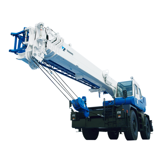
- Page 3 Foreword 2. External view The following is the traveling posture of the H-type outrigger specification machine. Front, rear, right, and left are the directions viewed from a position when operator sits on operator's seat with the boom directed to the front of the frame. Those directions remain invariant regardless of slewing direction of the superstructure.
- Page 4 Foreword 3. Outline of specifications Spec. No. GR-300E-3-00102 Item 2M2D (General Export) No. of boom sections No. of jib stages (base (jib 1), top (jib 2)) Single top Fitted Main winch Fitted Auxiliary winch Fitted Winch Winch brake Automatic brake (Neutral brake) Drum Visual type Fitted...
- Page 5 Foreword 4. Conversion table Length millimeter, mm centimeter, cm meter, m inch, in, ” foot, ft, ’ mile, mi kilometer, km 1×10 1×10 3.93701×10 3.28084×10 1.60934 1×10 1×10 3.93701×10 3.28084×10 6.21373×10 1×10 1×10 3.93701×10 3.28084 2.54×10 2.54 2.54×10 8.33333×10 3.048×10 3.048×10 3.048×10 1.2×10...
- Page 6 Foreword Pressure kgf/cm lbf/in , psi 1×10 1×10 1.01972×10 1.45038×10 1×10 1×10 1.01972×10 1.45038×10 1×10 1×10 1.01972×10 1.45038×10 9.80665×10 9.80665×10 9.80665×10 1.42233×10 6.89476×10 6.89476 6.89476×10 7.03072×10 kgf/cm 1×10 1.01972 1×10 1.0972×10 9.80665×10 9.80655×10 Torque inch-pound, N-cm kgf-cm kgf-m foot-pound, ft-lbf in-lbf 1×10 1.01972×10...
- Page 7 Foreword 5. Drawing method of illustrations in this service manual The third angle projection method of mechanical drawing is used for the illustrations in this service manual. The third angle projection method is generally composed of the front view (the figure viewed from the front: A), top view (the figure viewed from the top: B), and right-side view (the figure viewed from the right: C) as shown below.
- Page 8 6. Group index Data, Adjustment and Checks System Diagrams WA04-4880E...
- Page 9 Foreword 7. Contents Spec. No. GR-300E-3-00102 Section 2M2D (General Export) Data, Adjustment and Checks Service Data Adjusting pressure (Hydraulic Pressure) Adjusting pressure (Pneumatic Pressure) Air Bleeding Procedure Adjusting procedure (Electric) Assembly Adjustment (Crane Operation) Assembly Adjustment (Traveling Device) Operation Check (Crane Operation) Operation Check (Traveling Device) Inspection and Maintenance Y-10...
- Page 10 Foreword Spec. No. GR-300E-3-00102 Section 2M2D (General Export) Location of Installation Hydraulic Parts Location Diagram (Upper) Hydraulic Parts Location Diagram (Lower) Hydraulic Parts Location Diagram (Torque Converter) Pneumatic Parts Location Diagram Electric Parts Location Diagram (Upper) Z-10 Electric Parts Location Diagram (Lower) Z-11 Harness Diagrams Harness (Upper)
-
Page 11: Table Of Contents
Data, Adjustment and Checks Contents Y-1 Service Data ........1 Items ............ 13 Winch ............13 Amounts of oil and coolant ......1 Telescoping ..........15 Elevating ........... 16 Operating speed ........1 Steering ............. 17 Slewing............18 Hydraulic device ........2 Outrigger ........... - Page 12 Hydraulic motor assy ......27 Installing and adjusting anti-buckling bolts for telescoping cylinders ..36 Slewing motor ........... 27 Winch motor ..........27 Air conditioner motor ........ 27 Y-7 Assembly Adjustment Slewing control valve (Traveling Device) ....37 (back-pressure valve) ....28 Service brake adjustment ......
- Page 13 Boom telescoping control ......45 Suspension lock ........46 Warning ..........47 Outrigger slide plate adjustment ..... 47 10. Over-unwinding detection check (option) ........48 11. Eco mode operation check ..... 48 Y-9 Operation Check (Traveling Device) ....49 Exhaust brake ......... 49 Automatic transmission ......
-
Page 14: Service Data
Service Data Service Data [NOTICE] Standard values are values at time of vehicle shipment from TADANO. Limit values are the limits at which adjustment or part replacement is necessary. 1. Amounts of oil and coolant (1L = 2.64172 × 10... -
Page 15: Hydraulic Device
Service Data 3. Hydraulic device 3.1 Hydraulic pump Item Standard value Remarks Speed reducing ratio 0.918 Idling (min 763 ± 54 Eng. 700 ± 50 Crane pump Max. (min 2070 Eng. 1900 (PTO - ON) Displacement (cm /rev) 70 + 63 Speed reducing ratio 1.066 Idling (min... -
Page 16: Hydraulic Cylinder
Service Data 3.3 Hydraulic cylinder (1 m = 3.28084 ft) (1 mm = 3.93701 × 10 Remarks Standard Item value Condition and method Safety and notice Inspection conditions 1. Boom angle: 60°±2° (Lowering operation) 2. Boom full retraction 3. Engine stop 1°... - Page 17 Service Data Remarks Standard Item value Condition and method Safety and notice Inspection conditions 1. Angle lowered by 5°±2° from jib tilt angle upper limit (minimum offset angle) 2. Boom angle: 60°±2° 3. Engine stop 1° or less/ 4. No load tilt 2 hours Inspection method...
-
Page 18: Slewing Section
Service Data 4. Slewing section (1 mm = 3.93701 × 10 Item Standard value Remarks Horizontal play 4 mm or less Amount of slewing play Vertical play 2 mm or less 5. Boom section 5.1 Slide plate (1 mm = 3.93701 × 10 Replacement thickness Standard thickness... -
Page 19: Boom Bending And Deformation
Service Data 5.2 Boom bending and deformation (1 mm = 3.93701 × 10 Item Standard value (mm) Remarks Overall boom bending No significant vertical or horizontal Set the machine (at full extension, maximum elevation angle, with bends shall be found along the entire level. -
Page 20: Jib Bending And Deformation
Service Data 5.3 Jib bending and deformation (1 mm = 3.93701 × 10 Item Standard value (mm) Remarks Check for bending of the whole jib a ≤ 8.5 a ≤ 1.5 + L /1000 No significant bending in vertical and L = 7000 horizontal direction shall be found. -
Page 21: Sheave
Service Data 5.5 Sheave (1 mm = 3.93701 × 10 Standard of Limit of minor Item minor diameter diameter (mm) Remarks (mm) (*1) Determination of limit minor • Top boom upper diameter • Top boom lower 315.2 (When rope of nominal diameter •... -
Page 22: Criteria For Maintenance
Service Data 6. Criteria for maintenance and replacement of vehicle 6.1 Power transmission device Item Standard value Remarks Idling (min 700 ± 50 2665 ± 50 1900 Eco mode : OFF (Reference value) Max. (min Check conditions • PTO switch : OFF When torque converter stalls Approx. -
Page 23: Steering Device
Service Data 6.3 Steering device (1 mm = 3.93701 × 10 Item Standard value Remarks –0.025 Cylinder side –0.05 Pin outer diameter (mm) –0.025 Rod side –0.05 Clearance above and below axle (mm) 0 to 0.05 Camber (°) Caster (°) Kingpin angle (°) Toe-in (mm) +1.0 to +3.0... -
Page 24: Mass Table
Y-1 . Y-1 . Service Data 7. Mass table The dry weights of the major components are shown in the table below. Refer the weights, and select appropriate hoisting devices when removing and installing the component. Mass Assembly name kg (lb) Slewing frame assembly (not including boom, elevating cylinder, slewing bearing, and 3850 (8490) -
Page 25: Adjusting Pressure
Adjusting Pressure (Hydraulic Pressure) Adjusting Pressure (Hydraulic Pressure) 1. Location (position of relief valve etc.) WY02-1792E... -
Page 26: Items
2.1 Winch [NOTICE] Oil temperature: 50±5°C (113 - 131°F) (Hydraulic oil: TADANO Hydraulic Oil LL) Confirm set pressure on the crane information screen in the maintenance mode of AML. Shift the control lever or switch while the engine is idling, then increase engine speed. - Page 27 Adjusting Pressure (Hydraulic Pressure) WY02-1792E...
-
Page 28: Telescoping
2.2 Telescoping [NOTICE] Oil temperature: 50±5°C (113 - 131°F) (Hydraulic oil: TADANO Hydraulic Oil LL) Confirm set pressure on the crane information screen in the maintenance mode of AML. Shift the control lever or switch while the engine is idling, then increase engine speed. -
Page 29: Elevating
2.3 Elevating [NOTICE] Oil temperature: 50±5°C (113 - 131°F) (Hydraulic oil: TADANO Hydraulic Oil LL) Confirm set pressure on the crane information screen in the maintenance mode of AML. Shift the control lever or switch while the engine is idling, then increase engine speed. -
Page 30: Steering
Adjusting Pressure (Hydraulic Pressure) 2.4 Steering [NOTICE] Oil temperature: 50±5°C (113 - 131°F) (Hydraulic oil: TADANO Hydraulic Oil LL) Shift the control lever or switch while the engine is idling, then increase engine speed. Engine Set pressure Item Check procedure... -
Page 31: Slewing
2.5 Slewing [NOTICE] Oil temperature: 50±5°C (113 - 131°F) (Hydraulic oil: TADANO Hydraulic Oil LL) Confirm set pressure on the crane information screen in the maintenance mode of AML. Shift the control lever or switch while the engine is idling, then increase engine speed. -
Page 32: Outrigger
Adjusting Pressure (Hydraulic Pressure) 2.6 Outrigger [NOTICE] Oil temperature: 50±5°C (113 - 131°F) (Hydraulic oil: TADANO Hydraulic Oil LL) Shift the control lever or switch while the engine is idling, then increase engine speed. Engine Set pressure Item Check procedure... -
Page 33: Lower Pilot Pressure
Adjusting Pressure (Hydraulic Pressure) 2.7 Lower pilot pressure [NOTICE] Oil temperature: 50±5°C (113 - 131°F) (Hydraulic oil: TADANO Hydraulic Oil LL) Engine Set pressure Item Check procedure speed (Mark) kgf/cm (min 1. Connect a pressure gauge to the pressure check port (J). -
Page 34: Remote Control Pilot Pressure
Adjusting Pressure (Hydraulic Pressure) 2.8 Remote control pilot pressure [NOTICE] Oil temperature: 50±5°C (113 - 131°F) (Hydraulic oil: TADANO Hydraulic Oil LL) Shift the control lever or switch while the engine is idling, then increase engine speed. Engine Set pressure... -
Page 35: Torque Converter Oil Pressure
Y-2 . Y-2 . Adjusting Pressure (Hydraulic Pressure) 2.9 Torque converter oil pressure Engine Set pressure Item Check procedure speed kgf/cm (min 1. Turn the PTO switch OFF with the air 1.9 or over 19.4 or over 275 or over Torque (IDL.) conditioner OFF. - Page 36 Y-3 . Y-3 . Adjusting Pressure (Pneumatic Pressure) Adjusting Pressure (Pneumatic Pressure) Set pressure No. in circuit Item Remarks diagram kgf/cm Check that the air dryer Pressure regulator Turning on pressure 710 ± 20 7.2 ± 0.2 103 ± 3 recovers its performance during +0.3...
-
Page 37: Air Bleeding Procedure
Air Bleeding Procedure Air Bleeding Procedure 1.2 Main pump 1. Hydraulic pump 1. Fill the hydraulic oil tank with the hydraulic oil. (If the suction section is disassembled due to repair [NOTICE] or other reasons, bleed from the air-bleed plug on Be sure that the following conditions are met before the suction side as described above.) starting the engine. -
Page 38: (When The Tank Pressurization Tool Is Used)
Air Bleeding Procedure 1.3 Main pump (when the tank pressurization 6. If any abnormality is found, bleed the hydraulic tool is used) pump again. [NOTICE] 7. If there is no abnormal noise, turn ON the PTO Adjust the pressure setting of the tank pressurization tool to 15 kPa {0.15 kgf/cm²} (2.2 psi). -
Page 39: Winch Brake
Air Bleeding Procedure 2. Winch brake 3. Service brake [NOTICE] [NOTICE] Bleed the main and auxiliary winch circuits by The vehicle has two boosters; one for the front following the procedures below. The procedures are wheel brakes and the other for the rear wheel common to the both circuits. -
Page 40: Hydraulic Motor Assy
Air Bleeding Procedure 4. Hydraulic motor assy (2) Perform the hoisting up or hoisting down operation slowly (1st speed or lower) for one 4.1 Slewing motor minute or more. [NOTICE] Do not apply any load to the motor before completing air bleeding. Bleed the slewing motor by following either (1), (2) or (3). -
Page 41: Slewing Control Valve
Air Bleeding Procedure 5. Slewing control valve 2 Elevating (back-pressure valve) Pull out the connector (CN100) of the AML vent solenoid valve. [NOTICE] Move the boom elevating lever fully to the boom Conditions lowering side. Keep the above conditions for 30 Engine speed : Max. -
Page 42: Positive Control Circuit
Y-4 . Y-4 . Air Bleeding Procedure 7. Positive control circuit 8. Hydraulic valve (winch brake) While any of the crane operations described in 6. [NOTICE] is performed, loosen the air-bleed plug near the Bleed this valve after the pilot circuit (hydraulic pilot control valve) (See the section 6.) and the positive lower pump to bleed the positive control circuit. -
Page 43: Adjusting Procedure (Electric)
Adjusting Procedure (Electric) Adjusting Procedure 2. Jib stowed detection switch (CN572) (Electric) △ 343-548-72100 1. 3rd/top boom full retraction detection Adjust the switch position so that the dimension A switch (CN859) +0.5 +0.02 becomes 4 mm (0.16 in) with the jib stowed. △... -
Page 44: Main Winch Drum Rotation
Adjusting Procedure (Electric) 3. Main winch drum rotation detection 5. Over-front detection switch (CN521) switch (CN591) △ 349-520-50000 △ 344-939-10000 Fully retract the boom and slewing it to the over-front. Insert the slewing lock pin and set the boom angle to Adjust the switch position so that the dimension A 60°... -
Page 45: Control Lever Stand Position
Adjusting Procedure (Electric) 6. Control lever stand position detection 7. Straight ahead detection switch switch (left) (CN529) (CN408) △ △ 343-232-51000 349-609-80000 △ 343-233-01000 Set the clearance B to minimum, and adjust switch Set the rear wheels in a straight-forward position, +0.5 position so that the dimension A becomes 1.5 and adjust the switch position so that the dimension... -
Page 46: Over-Unwinding Detection Switch
Y-5 . Y-5 . Adjusting Procedure (Electric) 8. Over-unwinding detection switch (main winch) (option) (CN595) △ 344-446-95000 Adjust the roller assy position by the bolt Z so that the dimension A becomes 5 mm (0.20 in), and lock the bolt Z with a nut. Squeeze the roller assy of switch upward further by 1.5 mm (0.06 in) after the switch’s contact is shifted (opened/closed). -
Page 47: Assembly Adjustment
Assembly Adjustment (Crane Operation) Assembly Adjustment (Crane Operation) 1. Adjusting boom telescoping wire ropes 1. After assembling each boom section and adjusting the slide plate by adding or removing shims, retract the boom fully. (Keep the wire rope free.) [NOTICE] Loosen the sway stopper bolt (see Y-6 1.5.) on the lower part of each boom section until it is out of contact with the support. - Page 48 Assembly Adjustment (Crane Operation) 3. Tighten the adjustment nut for top boom section retraction wire rope until the top boom section stopper seats against the 3rd boom head. Adjusting nut for top boom section retraction wire rope Contact IWY05-0590E05 4. After checking the contacting condition of stopper for each boom section, fix adjuster section for each extension and retraction wire rope with two nuts.
-
Page 49: Installing And Adjusting Anti-Buckling Bolts For Telescoping Cylinders
Y-6 . Y-6 . Assembly Adjustment (Crane Operation) 2. Installing and adjusting anti-buckling bolts for telescoping cylinders 1. Connect the boom and telescoping cylinder using the pins A and B. 2. Adjust the bolt C locked with nuts D and E so that it can be turned by hand and the clearance (S) is 0.5mm (0.02in) or less. -
Page 50: (Traveling Device)
Assembly Adjustment (Traveling Device) Assembly Adjustment 1.3 Check after replacing brake hose (Traveling Device) After you replace the brake hoses and so on, 1. Service brake adjustment make sure that any contact does not occur between the hoses and the structures in any 1.1 Adjusting the brake pedal situation. -
Page 51: Accelerator Sensor Assembly And Adjustment
Assembly Adjustment (Traveling Device) 2.2 Accelerator sensor assembly and 6. Positioning of full stroke side stopper adjustment Adjust the position of the sensor with bolt C and [NOTICE] lock with the nut so that each sensor output (Out1 Do not touch the terminal directly because the static (white-black) and Out2 (blue-green)) becomes 4.5 electricity tolerance of the sensor is weak. - Page 52 Assembly Adjustment (Traveling Device) Accelerator sensor output diagram For positioning procedures 4., 5. and 6. mentioned as above, check the voltage at the connector terminals shown below. △ 347-112-62600 △ 347-113-32000 △ 347-113-70000 WY05-4221E...
-
Page 53: Parking Brake Adjustment
Assembly Adjustment (Traveling Device) 3. Parking brake adjustment 4. Tire and steering angle adjustment 4.1 Tire air pressure 3.1 Connecting the parking brake and brake Unit: kPa {kgf/cm } (psi) chamber Spec. No.: GR-350-3 and GR-300E-3 (1) Shift the rod of the brake chamber to the end of On-rubber Tire size Traveling... -
Page 54: Engine Speed (And Governor Setting)
Assembly Adjustment (Traveling Device) 5. Engine speed (and governor setting) 6. Torque converter and transmission 6.1 Maximum allowable speed [NOTICE] Units: km/h (MPH) Before checking the engine speed, run the engine Combination to warm it up. (Torque converter oil temperature High position Low position meter display... -
Page 55: Retightening The Hub Nuts
Y-7 . Y-7 . Assembly Adjustment (Traveling Device) 7. Retightening the hub nuts • Retighten the hub nut with the tightening torque of 640 ± 30 N-m {6500 ± 300 kgf-cm} (472 ± 22 ft-lbf). • Put the retightening torque for the hub nuts (the torque of the latest tightening) on the hub nut torque check record. -
Page 56: Operation Check
Operation Check (Crane Operation) Y-8 Operation Check (Crane Operation) 1. Outrigger status indicator Main switch : ON Shift lever : Not in N position Operate the outrigger extend/retract selector switch. Icon flashes on the AML display. Press all outrigger control switch. Outriggers do not operate. -
Page 57: Hoisting
Operation Check (Crane Operation) 2. Hoisting 2. Icon flashes on the AML display. 3. Check that the extension width smaller than the [Condition] detected value can be registered on AML • Load : None manually. • Engine speed : Approximately 700 min to medium speed 5. -
Page 58: Boom Telescoping Control
Operation Check (Crane Operation) 6. Boom telescoping control Retraction [Boom length: 9.7 - 31.0 m (31.8 - 101.7 ft)] Approximately 24.38 m (80.0 ft) boom CN503(1): Emergency telescoping switch for 3rd/top boom CN503(2): Emergency telescoping switch for 3rd/top boom retract. 2nd boom CN506: 3rd/top boom extending switch CN859: 3rd/top boom full retraction detection switch... -
Page 59: Suspension Lock
Operation Check (Crane Operation) 7. Suspension lock [NOTICE] Condition • Crane status for check : On-rubber configuration : Boom forward (over-front) • Engine speed : Approximately 700 min • Vehicle speed : 0 km/h • Shift lever : N position While PTO is disengaged (OFF), suspension can be locked and unlocked. -
Page 60: Warning
Operation Check (Crane Operation) 8. Warning [NOTICE] For the location of the buzzers, refer to "Z-10 Electric Parts Location Diagram (Upper), 1. Inside cab ". Warning Item Sound Checking procedure buzzer • 280Hz Buzzer sounds at 100% when main switch is ON and PTO Buzzer AML limit •... -
Page 61: Over-Unwinding Detection Check
Y-8 . Y-8 . Operation Check (Crane Operation) 10. Over-unwinding detection check (option) Check that the over-unwinding detection activates and the winch stops when the wire rope on the winch drum decreases to or below 3 turns. 11. Eco mode operation check [NOTICE] For the location of the switch, refer to “Z-10 Electric Parts Location Diagram (Upper), 1. -
Page 62: Operation Check
Operation Check (Traveling Device) Operation Check 2. Automatic transmission (Traveling Device) [1 km/h = 0.6214 MPH] [NOTICE] 1. Exhaust brake Numbers indicate speedometer readings. (units: km/h) [NOTICE] ( ) Indicates lock up ON and OFF values. Jack up the crane and make sure the crane is set up horizontally and all tires are off the ground. -
Page 63: Steering Mode Change
Operation Check (Traveling Device) 3. Steering mode change Change the steering mode switch to 4-wheel or crab steering. Turn the steering wheel, and check the steering. Check that the indicator in the right bottom of the instrument panel is ON, except when rear wheels are out of straight-ahead condition. -
Page 64: Overshift Prevention
Operation Check (Traveling Device) 5. Overshift prevention [1 km/h = 0.6214 MPH] [NOTICE] Jack up the vehicle and shift to 4WD High position. Perform the operations below and check the shift position with the combination meter. 1. Move the shift lever to “D” and increase speed to 32 km/h or more. -
Page 65: Warning
Operation Check (Traveling Device) 6. Warning [NOTICE] For the location of the buzzer, refer to "Z-10 Electric Parts Location Diagram (Upper), 1. Inside cab " . [1 km/h = 0.6214 MPH] Warning Item Sound Check conditions buzzer Buzzer sounds when the following conditions are met. Total air low 1. -
Page 66: Off-Straight-Ahead Wheel Indicator
Y-9 . Y-9 . Operation Check (Traveling Device) 8. Off-straight-ahead wheel indicator and warning [NOTICE] Jack up the vehicle. Engine speed: idling (700 min Check the following. Status of off-straight Warning Orientation of Steering Operation buzzer -ahead rear wheel mode wheel (CN818) indicator... -
Page 67: Inspection And Maintenance
Y-1 0 . Y-1 0 . Inspection and Maintenance Y-10 Inspection and Maintenance 1. Refer to “Inspection and Maintenance” in “Operation Manual” of its applicable crane. 2. Maintenance of line filter Maintenance table Inspection and maintenance Parts interval Parts name (used) Type of work Points/Quantity 1200h... -
Page 68: Boom Connecting Pin
Y-1 1 . Y-1 1 . Boom Connecting Pin and Thread Size Table Y-11 Boom Connecting Pin and Thread Size Table (Note): “ ” means that more than one spec. No. are applicable. (Unit: mm) (1 mm = 0.039 inch) GR-1000-3- GR-800E-3- GR-550-3-... - Page 69 System Diagrams Contents Z-1 Hydraulic Circuit ......1 Electric circuit (SCT) ......... 16 Electric circuit (GSMT) ......17 Comparison table of hydraulic parts (part No., part name, coordinate and location) ....1 Z-5 Electric Circuit (Lower) ....18 Hydraulic circuit diagram ......2 Composition of electric circuit diagram ..
- Page 70 Pilot ............ 28 Relay assy (inside cab) ......39 Steering ..........29 Slewing table, boom ........ 40 10. Air conditioner ......... 29 Pressure switch installation diagram ..41 11. Operation assy, operation valve ....30 Two-blocking ........... 42 Boom (two-blocking) ......... 42 12.
- Page 71 Harness (SCT) ......... 60 Electric circuit (beacon lamp) ....81 Composition of electric circuit diagram ..81 Harness (GSMT) ........61 Comparison table (connector No., usage and paragraph No.) ....82 Electric circuit (beacon lamp) ....83 Z-13 Harness (Lower) ......62 Lamp (beacon) ........
-
Page 72: Hydraulic Circuit
Hydraulic Circuit Z - 1 Z - 1 “Location” shows each applicable paragraph No. of this manual’s contents. Refer to the contents. Hydraulic Circuit 1. Comparison table of hydraulic parts (part No., part name, coordinate and location) Hydraulic Hydraulic Hydraulic Part No. -
Page 73: Hydraulic Circuit Diagram
Z-1. Z-1. Z-1. Hydraulic Circuit 2. Hydraulic circuit diagram [NOTICE] ・Refer to page 1 about hydraulic parts name and number. ・Refer to Y-2 Adjusting pressure (hydraulic pressure) about relief symbol (A, B, C, D, E, F, G, H, I, J, K, L, V, W) in the figure. -
Page 74: Torque Converter Circuit
Z-2. Z-2. Z-2. Torque Converter Circuit Z-2 Torque Converter Circuit (Parts, location: refer to Z-8) Torque converter case Transmission case G3/8 G3/8 Lubrication relief valve Oil cooler M16×1.5 Thermo. sensor (CN427) (T/C oil temp.) SL43 SL42 SL44 G3/8 G3/8 SL45 Lock up P.T.O SL49... -
Page 75: Pneumatic Circuit
Z-3. Z-3. Z-3. Pneumatic Circuit Z-3 Pneumatic Circuit (Parts, location: refer to Z-9) (1L=2.64172×10 gal) Center joint Dual brake valve FRONT (CN583) Disc brake Air pressure sensor (SL54) Air solenoid valve (exhaust brake) (energized : braking) Air cylinder REAR (exhaust brake) (SL51) 129-1 129-2... - Page 76 Electric Circuit (Upper) Z-4 Electric Circuit (Upper) 1. Composition of electric circuit diagram The electric circuit diagram of this machine is composed of “Z-4 Electric Circuit (Upper)” and “Z-5 Electric Circuit (Lower)” mainly. The electric circuit (upper) is shown by following block diagram. Z-4 4.8 Z-4 4.7 Z-14...
-
Page 77: Electric Circuit (Upper)
Electric Circuit (Upper) Z - 4 2. Reading method of electric circuit 5) Shield line(GND) diagram Wire to establish GND by diverging another wire to the shield line 2.1 Notational convention S ○○ – AA ■Conditions Signal distinction Wire number symbol 1. -
Page 78: Composition Of Switch (For Reference)
Toggle switch (the switch of lower electric circuit contains it.) Switch Middle Down <①-3> ①-2 Power window AML override switch (for GR-800EX-3, GR-600EX-3, GR-500EX-3 and GR-300EX-3) ①-3 Outrigger operation box illumination ②-3 Lower outrigger operation jack/slide selection ②-3,⑤-6 1-②,4-⑤ AML override Lower outrigger operation extending/retracting selection <②-3,⑤-6>... -
Page 79: Electric Circuit
(Note): Electric Circuit (Upper) Z - 4 Z - 4 The connector with “#” is not applied to this machine. “Electric circuit diagram” and “Harness diagram” show each applicable paragraph No. of this manual’s contents. Refer to the contents. 3. Comparison table (connector No., usage, coordinate and paragraph No.) Electric Electric Electric... - Page 80 Electric Circuit (Upper) Z - 4 Z - 4 Electric Electric Electric Electric Harness Harness CN No. Usage circuit circuit CN No. Usage circuit circuit diagram diagram coordinate diagram coordinate diagram CN934 Vibration type aux. winch drum rotation indicator CN1613 Fuse box (3) N-17 Z-4 4.2 K-19...
- Page 81 Electric Circuit (Upper) 4 Electric circuit 4.1 Electric circuit (crane) JC102-1 GREEN JC102-2 GREEN JC102-3 GREEN JC02-1 GREEN JC02-2 GREEN JC02-3 GREEN JC05-1 BLUE JC05-2 GREEN JC05-3 GREEN JC01-1 GREEN JC01-2 GREEN JC01-3 GREEN JC07-1 BLUE JC07-2 BLUE JC07-3 JC101-1 BLUE JC101-2 GREEN...
- Page 82 Electric Circuit (Upper) Applicable serial No. : 561905-- 4.2 Electric circuit (carrier) Idling adjustment switch Combination meter GREEN GREEN GREEN Combination switch CN587B BLUE GREEN BLUE GREEN GREEN GREEN BLUE GREEN GREEN GREEN GREEN BLUE BLUE GREEN GREEN [NOTICE] CN1020 To electric circuit (crane) (S22-040) R Flasher unit...
-
Page 83: Electric Circuit (Slewing Table, Right)
Z- 4 Z- 4 Z- 4 Electric Circuit (Upper) 4.3 Electric circuit (slewing table, right) [NOTICE] 1. If not specified, wire type is AVS and wire size is 0.5mm Joint connector CN829A (412AA) G/W CN890 Joint connector to "crane" External indicator lamp (red) 100% (B53AB) B (B53AA) B (B05AF) B... -
Page 84: Electric Circuit (Slewing Table, Left)
Z- 4 Z- 4 Z- 4 Electric Circuit (Upper) 4.4 Electric circuit (slewing table, left) [NOTICE] 1. If not specified, wire type is AVS and wire size is 0.5mm Joint connector to “boom” Joint connector to “crane” CN993 CN1206 (S01-013)G (S01-013) G Boom angle detector (signal) Boom angle detector (signal) -
Page 85: Electric Circuit (Boom)
Z- 4 Z- 4 Z- 4 Electric Circuit (Upper) Applicable serial No. : 561927-- 4.5 Electric circuit (boom) [NOTICE] 1. If not specified, wire type is AVS and wire size is 0.5mm Joint connector to “slewing table, left” CN888 CN853A (233AA) Y/B 0.85 (S45-117) O... -
Page 86: Electric Circuit (Two-Blocking)
Z- 4 Z- 4 Z- 4 Electric Circuit (Upper) 4.6 Electric circuit (two-blocking) [NOTICE] 1. If not specified, wire type is AVS and wire size is 0.5mm 3rd/top boom full retraction detection switch Two-blocking detection switch (boom) (right) Joint connector to “boom” (contact close : full retraction) CN859 (contact open: two-blocking) -
Page 87: Electric Circuit (Sct)
Z- 4 Z- 4 Z- 4 Electric Circuit (Upper) 4.7 Electric circuit (SCT) [NOTICE] 1.If not specified, wire type is CAVS and wire size is 0.5mm SCT (Satellite communications terminal) CN1068 (016AC) Y/L KEY_ON (006AC) O BATT (B51AF) B 1-11 (B51AG) B 1-12 (B51AH) B... -
Page 88: Electric Circuit (Gsmt)
Z- 4. Z- 4. Z- 4. Electric Circuit (Upper) 4.8 Electric circuit (GSMT) [NOTICE] 1.If not specified, wire type is CAVS and wire size is 0.5mm Joint connector to “carrier” GSMT (global system for mobile communications terminal) CN1072 CN1584 (016AC) Y/L (016AC) Y/L KEY_Power_Supply 1-15... -
Page 89: Electric Circuit (Lower)
Electric Circuit (Lower) Z-5 Electric Circuit (Lower) 1. Composition of electric circuit diagram The electric circuit diagram of this machine is composed of “Z-4 Electric Circuit (Upper)” and “Z-5 Electric Circuit (Lower)” mainly. The electric circuit (lower) is shown by following block diagram. Z-5 3.3 Electric circuit (rear steering) - Page 90 (Note): Electric Circuit (Lower) Z - 5 Z - 5 “Electric circuit diagram” and “Harness diagram” show each The connector with “#” is not applied to this machine. applicable paragraph No. of this manual’s contents. Refer to the contents. 2. Comparison table (connector No., usage, coordinate and paragraph No.) Electric Electric Electric...
- Page 91 Electric Circuit (Lower) 3 Electric circuit 3.1 Electric circuit (main) YELLOW BLUE BLUE YELLOW BLUE GREEN [NOTICE] For VCU maintenance CN1 (main board) CN619 Joint connector to “rear steering” JC07-1 JC07-2 JC07-3 JC04-1 JC04-2 JC04-3 AMP025 CN600 1. If not specified, wire type is CAVS and wire size is 0.5mm CN1600 To electric circuit (engine) (800AA) L/R...
-
Page 92: Electric Circuit (Engine)
Electric Circuit (Lower) 3.2 Electric circuit (engine) [NOTICE] 1. If not specified, wire type is AVS and wire size is 0.5mm WATER IN FUEL TO ENGINE CN1762 CN1797 (1403AA) BR/Y AVS 0.85 (1403AA) BR/Y INPUT To electric circuit (main) WATER IN FUEL SENSOR (670AH) B/Y AVS 0.85 (670AH) B/Y RETURN... -
Page 93: Electric Circuit (Rear Steering)
Electric Circuit (Lower) 3.3 Electric circuit (rear steering) [NOTICE] 1. If not specified, wire type is CAVS and wire size is 0.5mm Straight ahead detection switch Joint connector to “main” (contact close : straight ahead) CN1600 CN408 (S61-142) R (S61-142) R Sensor power supply (S61-143) W (S61-143) W... -
Page 94: Electric Circuit (Head Light)
Z-5. Electric Circuit (Lower) Z-5. 3.4 Electric circuit (head light) [NOTICE] 1. If not specified, wire type is AVS and wire size is 0.85mm Combination lamp (L) Side turn signal (L) Head lamp (L) Joint connector to “main” CN1529 (013AB) L/B Turn signal (142AB) BR/W Clearance lamp... -
Page 95: Hydraulic Parts Location Diagram (Upper
Hydraulic Parts Location Diagram (Upper) Hydraulic Parts Location Diagram (Upper) 1. Winch △ 343-465-10000 2. Telescoping △ 343-465-01000 △ 343-450-32000 △ 342-112-60000 WZ07-3762E... -
Page 96: Elevation
Hydraulic Parts Location Diagram (Upper) 3. Elevation △ 342-411-30000 △ 343-548-72500 △ 343-551-22500 4. Slewing △ 343-458-61000 △ WZ07-3762E 343-004-90001... -
Page 97: Return
Hydraulic Parts Location Diagram (Upper) 5. Return △ 6. Drain 343-458-62000 △ 343-465-03000 WZ07-3762E... -
Page 98: Gauge
Hydraulic Parts Location Diagram (Upper) 7. Gauge △ 343-450-35500 WZ07-3762E... -
Page 99: Pilot
Hydraulic Parts Location Diagram (Upper) 8. Pilot △ 343-458-63000 WZ07-3762E... -
Page 100: Steering
Hydraulic Parts Location Diagram (Upper) 9. Steering △ 347-221-11000 △ 347-225-71000 10. Air conditioner △ 345-109-41000 WZ07-3762E... -
Page 101: Operation Assy, Operation Valve
Z-6 . Hydraulic Parts Location Diagram (Upper) Z-6 . 11. Operation assy, operation valve △ 343-233-00000 △ 12. Pressure switch 343-232-50000 △ 343-636-03000 WZ07-3762E... -
Page 102: Suction
Hydraulic Parts Location Diagram (Lower) Hydraulic Parts Location Diagram (Lower) 1. Suction △ 346-415-31000 △ 347-329-00000 WZ07-4090E... -
Page 103: Steering, Suspension Lock
Hydraulic Parts Location Diagram (Lower) 2. Steering, suspension lock △ 347-905-80000 △ 347-221-50000 △ 346-415-32000 WZ07-4090E... -
Page 104: Outrigger (H Type)
Hydraulic Parts Location Diagram (Lower) 3. Outrigger (H type) △ 346-415-33000 4. Center joint △ 346-415-34000 WZ07-4090E... -
Page 105: Return
Z - 7 . Hydraulic Parts Location Diagram (Lower) Z-7. 5. Return △ 6. Outrigger main body (H type) 346-417-65000 △ 346-115-00000 WZ07-4090E... -
Page 106: Hydraulic Parts Location Diagram (Torque Converter
Z - 8 . Hydraulic Parts Location Diagram (Torque Converter) Z-8. Hydraulic Parts Location Diagram (Torque Converter) 1. Torque converter related △ 349-226-00000 △ 349-316-71001 △ 349-318-21000 WZ07-3781E... -
Page 107: Service Brake Related (Upper)
Pneumatic Parts Location Diagram Z - 9 Pneumatic Parts Location Diagram 1. Service brake related (upper) △ 347-218-90000 △ 343-450-20000 2. Service brake related (lower) △ 349-226-21000 △ 349-226-10000 △ WZ08-0620E 349-226-20000... -
Page 108: Control Parts (Lower)
Z - 9 . Pneumatic Parts Location Diagram Z-9. 3. Control parts (lower) △ 349-233-11000 △ 349-233-10000 WZ08-0620E... -
Page 109: Inside Cab
Z-10 Z-10 Z-10 Electric Parts Location Diagram (Upper) Z-10 Electric Parts Location Diagram (Upper) [NOTICE] Joint connector to “slewing table, left” : CN887,CN893,CN894, 1. (CN***) indicates whether the connector is used depending on 1. Inside cab CN1206,CN1332,(CN1333) Joint connector to “slewing table, right” :CN889,CN891 the machine specification and option. -
Page 110: Relay Assy (Inside Cab)
Z-10 Z-10 Z-10 Electric Parts Location Diagram (Upper) 2. Relay Assy (inside cab) Cab front Fuse box (3) Crane section relay a-contact Crane section relay Carrier section relay a-contact (Normal open type relay) (Normal open type relay) Fuse box (2) Spare Spare Spare... -
Page 111: Slewing Table, Boom
Z-10 Z-10 Z-10 Electric Parts Location Diagram (Upper) [NOTICE] 1. (CN***) indicates whether the connector is used depending on 3. Slewing table, boom Ground the machine specification and option. Refer to “Z-4 Electric Circuit (Upper) 3. Comparison table” whether the connector is used. 2. -
Page 112: Pressure Switch Installation Diagram
Z-10 Z-10 Z-10 Electric Parts Location Diagram (Upper) 4. Pressure switch installation diagram Aux. winch hoisting up Aux. winch hoisting down detection switch detection switch CN533 CN547 Aux. winch Main winch hoisting up Main winch hoisting down detection switch detection switch Switch operating list CN532 CN546... -
Page 113: Two-Blocking
Z-10 Z-10 Z-10 Electric Parts Location Diagram (Upper) 5. Two-blocking 5.1 Boom (two-blocking) CN859 Joint connector to “boom” Ground Harness (boom head) CN862 Two-blocking detection switch (boom) (right) CN1094 Two-blocking detection switch (boom) (left) Switch installed on left side Main two-blocking detection switch assy Snap pin When using main-hook, insert into the hole of the support. -
Page 114: Single Top (Two-Blocking)
Z-10 Z-10 Z-10 Electric Parts Location Diagram (Upper) 5.2 Single top (two-blocking) CN901A Harness (single top) Joint connector FRONT CN901A CN900 Joint connector Joint connector Harness (single top) CN900 Joint connector Sub two-blocking detection switch assy (when operating single top) Single top extended state Single top stowed state Boom left side... -
Page 115: Jib (Two-Blocking)
Z-10 Z-10 Z-10 Electric Parts Location Diagram (Upper) 5.3 Jib (two-blocking) CN1778 Joint connector Harness (jib 2, head) Harness (jib 1) Harness (jib 2, bottom) CN901B Joint connector FRONT CN948 CN948B Jib 1 Joint connector Joint connector CN948A Jib 2 Joint connector CN902 CN948... -
Page 116: Sct
Z-10 Z-10 Z-10 Electric Parts Location Diagram (Upper) 6. SCT GPS antenna CN1065 CN1066 Antenna (for satellite communications) GPS antenna CN1068 Harness (crane and carrier) Satellite communications Antenna (for satellite communications) terminal CN1072 CN1067 For maintenance terminal (Dr. T) Harness (SCT) Satellite communications terminal Connector (for satellite communications) Antenna cable... -
Page 117: Gsmt
Z-10. Z-10. Z-10. Electric Parts Location Diagram (Upper) 7. GSMT GPS antenna GSMT CN1065 CN1066 Harness (GSMT) Harness (crane and carrier) CN1584 GPS antenna CN1072 CN1067 For maintenance terminal (Dr. T) GSMT Parts connection detail GPS antenna FRONT CN1584 GSMT Harness (GSMT) CN1072 IWZ02-6400E08... -
Page 118: Lower, Main
Z-11 Z-11 Z-11 Electric Parts Location Diagram (Lower) Applicable serial No. : 561961-- Z-11 Electric Parts Location Diagram (Lower) [NOTICE] 1. Lower, main 1. (CN***) indicates whether the connector is used depending on the machine specification and option. Ground Refer to “Z-5 Electric Circuit (Lower) 2. Comparison table” whether the connector is used. Ground Ground Ground... -
Page 119: Lower Electric Unit Box
Z-11 Z-11 Z-11 Electric Parts Location Diagram (Lower) 2. Lower electric unit box (VCU, relay assy) Controller RA19 Spare RA37 Spare Spare RA27 RA11 Spare Spare Spare Spare a-contact Spare RA16 Spare RB10 RA17 (Normal open type relay) Spare Spare Spare Spare Spare... -
Page 120: Relay And Fuse Box (Under The Battery)
Z-11. Z-11. Z-11. Electric Parts Location Diagram (Lower) 3. Relay and fuse box (under the battery) CN1053 CN1075 Short bar side Fuse connector No. CN691 Fuse Pole CN No. Spare CN1680 CN1683 Fuse CN1681 CN731, CN732 (upper power supply) (75A) Fuse CN778 box (1) -
Page 121: Harness (Upper)
Harness (Upper) Z-12 Z-12 Z-12 (Note): Z-12 Harness (Upper) The connector with “#” is not applied to this machine. 1. Harness (crane and carrier) 1.1 Comparison table (connector No., usage and coordinate) Harness Harness Harness CN No. Usage diagram CN No. Usage diagram CN No. - Page 122 Z-12 Z-12 Z-12 Harness (Upper) Applicable serial No. : 561905-- 1.2 Harness (crane and carrier) Aux. winch high-speed Main winch high-speed SHIELD Flood lamp switch hoist up/down switch hoist up/down switch Eco mode switch SHIELD20 Emergency outrigger Roof washer switch Roof wiper switch CN470 CN846...
-
Page 123: Harness (Slewing Table, Right)
Z-12 Z-12 Z-12 Harness (Upper) 2. Harness (slewing table, right) CN828 CN829 Ground External indicator lamp (yellow) 90% External indicator lamp (red) 100% Over-front detection switch CN521 SHIELD 156AA B05AC 333AA SHIELD3 S03-AA CN890 SHIELD SHIELD4 S04-AA Joint connector to “crane” CN891 Ground (STD) Joint connector... -
Page 124: Harness (Slewing Table, Left)
Z-12 Z-12 Z-12 Harness (Upper) 3. Harness (slewing table, left) Top cylinder selection Joint connector CN993 solenoid valve (SL230) to “boom” S01-014 S01-013 CN230 Plug S01-016 S01-AB S01-015 303AA B01AF Pressure sensor SHIELD (main pressure) SHIELD2 CN581 Plug Plug S01-AB S05-009 S05-008 S05-007... -
Page 125: Harness (Boom)
Z-12 Z-12 Z-12 Harness (Upper) Applicable serial No. : 561927-- 4. Harness (boom) Jib stowed detection switch Joint connector to “slewing table, left” CN572 CN888 250AA B04AA 367AA S45-117 S45-154 S45-119 Plug S45-113 S45-115 Plug Plug E004 Ground B04AC Joint connector COTØ22 to “slewing table, left”... -
Page 126: Harness (Two-Blocking)
Z-12 Z-12 Z-12 Harness (Upper) 5. Harness (two-blocking) 5.1 Harness (boom head) B60AB E015 Ground Two-blocking detection switch (boom) (right) Joint connector to ”boom” Green tape 3rd/top boom full retraction detection switch CN862 COT Ø 07 CN859 0.75B 816AA 839AA 816AA LG/B LG/B... -
Page 127: Harness (Single Top)
Z-12 Z-12 Harness (Upper) 5.2 Harness (single top) CN901A CN900 COTΦ07 C06-018 C06-019 C06-019 C06-018 Joint connector Joint connector IWZ04-5190E06 WZ04-5380E 345-007-12100... -
Page 128: Harness (Jib 1)
Z-12 Z-12 Harness (Upper) 5.3 Harness (jib 1) CN948 CN901B COT Ø 10 7250 C06-018 C06-019 C06-018 C06-019 Yellow tape Yellow tape Joint connector Joint connector IWZ04-5190E07a WZ04-5380E 343-732-21100... -
Page 129: Harness (Jib 2, Bottom)
Z-12 Z-12 Harness (Upper) 5.4 Harness (jib 2, bottom) CN948B CN1778 COT Ø 10 C10-019 C10-018 C10-019 C10-018 Joint connector Joint connector IWZ04-5190E08a WZ04-5380E 343-732-21200... -
Page 130: Harness (Jib 2, Head)
Z-12 Z-12 Harness (Upper) 5.5 Harness (jib 2, head) CN948A Joint connector C09-019 C09-018 CN902 CN1778 COT Ø10 6550 COT Ø10 C12-019 C12-018 C11-018 C11-019 N001 Joint connector Joint connector IWZ04-5190E09a WZ04-5380E 343-732-21300... -
Page 131: Harness (Sct)
Z-12 Z-12 Harness (Upper) 6. Harness (SCT) Joint connector to “carrier” CN1072 CN1068 821AA 826AA B51AE 006AC 016AC 821AA 006AC 016AC 822AA 822AA 826AA B51AH B51AG B51AF N005 IWZ04-5190E10 WZ04-5380E 344-941-00101... - Page 132 Z-12. Z-12. Harness (Upper) 7. Harness (GSMT) IWZ04-5190E11a WZ04-5380E 344-947-70100...
-
Page 133: Harness (Lower)
Harness (Lower) Z-13 Z-13 Z-13 (Note): The connector with “#” is not applied to this machine. Z-13 Harness (Lower) 1. Harness (main and engine) 1.1 Comparison table (connector No., usage and coordinate) Harness Harness Harness CN No. Usage diagram CN No. Usage diagram CN No. - Page 134 Z-13 Z-13 Z-13 Harness (Lower) 1.2 Harness (main and engine) ECM (cummins) CN792 Head lamp relay Box assy (battery relay) S23-049 687AA 636AA 627AA Plug Plug Plug Plug Plug Plug 644AA 628AA CN707 CN706 Plug Plug Plug Plug Plug Plug Plug Plug LG/B...
- Page 135 Z-13 Harness (Lower) Z-13 1.3 Harness (cummins INSITE) Maintenance connector (cummins INSITE) CN691 Joint connector CN790 B01AE 602AA N001 S48-147 S48-148 IWZ04-502004E WZ04-5390E 349-316-32100...
- Page 136 Z-13 Harness (Lower) Z-13 2. Harness (rear steering) Joint connector to “main” CN1600 Straight ahead detection switch COTΦ07 CN408 S61-142 S61-143 S61-142 S61-146 S61-143 S61-AA S61-146 N002 SHIELD Yellow tape SHIELD61 S61-AA IWZ04-5200E03 WZ04-5390E 349-316-70400...
- Page 137 Z-13. Harness (Lower) Z-13. 3. Harness (head light) Joint connector to “main” CN1528 B10AD 145AB BR/W 146AB BR/B Joint connector to “main” CN1529 013AB 142AB BR/W Combination lamp (L) CN1008 B10AF CN712 Head lamp (L) 013AA CN701 COTØ07 COTØ07 Combination lamp (L) 145AB BR/W CN711...
-
Page 138: Anemometer (Option)
Z-14 Z-14 Z-14 Anemometer (Option) Z-14 Anemometer (Option) 1. Structure (anemometer) 1.1 Slewing table, boom CN1425 Anemometer Joint connector FRONT Cord reel CN1426 Joint connector Ground Harness (boom) Harness (slewing table, left) When not using anemometer To cord reel CN1495 Joint connector When operating boom, single top (Stowed position) - Page 139 Z-14 Z-14 Z-14 Anemometer (Option) Harness (Jib 2, bottom) 1.2 Jib CN1809 Harness (jib 1) Harness (jib 2, head) Joint connector CN1497 Joint connector CN1496B CN1496 FRONT Joint connector Joint connector CN1496A Jib 1 Joint connector Jib 2 CN1495 Joint connector CN1496 Joint connector CN1496B...
-
Page 140: Jib
Z-14 Z-14 Z-14 Anemometer (Option) 2. Electric circuit ( anemometer 2.1 Composition of electric circuit diagram The electric circuit (anemometer) is shown by following block diagram. Anemometer (option) Z-14 2.3.3 Electric circuit CN1426 Cord reel (jib) Z-14 2.3.1 Z-14 2.3.2 Electric circuit Electric circuit Jib 1... -
Page 141: Comparison Table
Z-1 4 Anemometer (Option) Z-1 4 2.2 Comparison table (connector No., usage and paragraph No.) “Electric circuit diagram” and “Harness diagram” show each applicable paragraph No. of this manual’s contents. Refer to the contents. Electric Harness CN No. Usage circuit diagram diagram CN634... -
Page 142: Electric Circuit (Slewing Table, Left)
Z-14 Z-14 Anemometer (Option) 2.3 Electric circuit 2.3.1 Electric circuit (slewing table, left) [NOTICE] 1. If not specified, wire type is CAVS and wire size is 0.5mm Joint connector to “boom” CN1425 (S64-171) R Aviation obstruction light power supply (24V) (S64-147) W Anemometer power supply (24V) (S64-148) B... -
Page 143: Electric Circuit (Boom)
Z-14 Z-14 Anemometer (Option) 2.3.2 Electric circuit (boom) Applicable serial No. : 561918-- [NOTICE] 1. If not specified, wire type is AVS and wire size is 0.5mm Joint connector Joint connector to “slewing table, left” to “jib” CN1425 CN1426 (S66-171) R (S66-171) (S66-147) W (S66-147) -
Page 144: Electric Circuit (Jib)
Z-14 Z-14 Z-14 Anemometer (Option) 2.3.3 Electric circuit (jib) [NOTICE] 1. If not specified, wire type is CAVS and wire size is 0.5mm Joint connector to “boom” Joint connector Anemometer CN1426 CN1495 When operating main boom or single top, Cord reel +... -
Page 145: General View (Anemometer)
Z-14 Z-14 Anemometer (Option) 3. General view (anemometer) IWZ02-6540E07a WZ02-6542E 344-961-21200... -
Page 146: Harness (Anemometer)
Z-14 Z-14 Anemometer (Option) 4. Harness (anemometer) 4.1 Harness (slewing table, left) SHIELD SHIELD SHIELD64A SHIELD64B S64AA Joint connector Joint connector S64AB to “boom” to “crane” CN1635 CN1425 COTΦ07 COTΦ10 COTΦ07 4200 S64-148 S64-147 S64-171 S64-147 1419AA B02AA S64AA S64-172 S64-171 S64-172 S64AB... -
Page 147: Harness (Boom)
Z-14 Z-14 Anemometer (Option) 4.2 Harness (boom) Applicable serial No. : 561918-- Joint connector Joint connector to “slewing table, left” to “jib” CN1425 CN1426 COTΦ07 COTΦ10 COTΦ07 7700 S66-171 S66-147 S66-148 S66-148 S66-147 S66-171 S66-172 S66-151 S66AB S64AA S66-151 S66-172 N001 SHIELD SHIELD66... -
Page 148: Harness (Jib 1)
Z-14 Z-14 Anemometer (Option) 4.3 Harness (jib 1) Joint connector Joint connector CN1496 CN1495 COTΦ13 7400 S62-147 S62-148 S62-147 S62-148 S62-171 S62-172 S62AB S62-171 S62-172 S62AA Yellow tape Yellow tape SHIELD SHIELD SHIELD62B SHIELD62A S62AB S62AA IWZ02-6540E10 WZ02-6542E 344-961-42100... -
Page 149: Harness (Jib 2, Bottom)
Z-14 Z-14 Anemometer (Option) 4.4 Harness (jib 2, bottom) Joint connector CN1496B Joint connector CN1809 COTΦ13 S62-148 S62-147 S62-171 S62-148 S62-147 S62AA S62-172 S62-171 S62AB S62-172 Plug SHIELD SHIELD SHIELD62B SHIELD62A S62AB S62AA IWZ02-6540E11 WZ02-6542E 344-961-42200... -
Page 150: Harness (Jib 2, Head)
Z-14. Z-14. Anemometer (Option) 4.5 Harness (jib 2, head) Joint connector CN1496A S62-148 S62-147 S62AF S62-172 S62-171 SHIELD SHIELD62F S62AF Joint connector CN1497 Joint connector CN1809 COTΦ13 COTΦ13 S62-148 S62-147 6950 S62-147 S62-148 S62-171 S62AE S62-172 S62-171 S62-172 S62AA Plug N001 SHIELD SHIELD... - Page 151 Z-15 Z-15 Z-15 Beacon Lamp (Option) Z-15 Beacon Lamp (Option) 1. Structure (beacon lamp) Front Beacon lamp Plug connector When not using beacon lamp, connect plug connectors together. CN1795 Beacon lamp switch CN1794 CN1794 Harness (beacon lamp) Joint connector CN1796 View A IWZ02-6820E01 WZ02-6950E...
- Page 152 Z-15 Z-15 Beacon Lamp (Option) 2. Electric circuit (beacon lamp) 2.1 Composition of electric circuit diagram The electric circuit (beacon lamp) is shown by following block diagram. Beacon lamp (option) Z-15 2.3 Z-4 4.2 Electric circuit Electric circuit (beacon lamp) (carrier) CN1796 IWZ02-6950E01...
-
Page 153: Beacon Lamp (Option
Z-1 5 Beacon Lamp (Option) Z-1 5 2.2 Comparison table (connector No., usage and paragraph No.) “Electric circuit diagram” and “Harness diagram” show each applicable paragraph No. of this manual’s contents. Refer to the contents. Electric Harness CN No. Usage circuit diagram diagram... - Page 154 Z-15 Z-15 Beacon Lamp (Option) 2.3 Electric circuit (beacon lamp) [NOTICE] 1. If not specified, wire type is AVS and wire size is 0.5mm Beacon lamp Joint connector to “carrier” CN1795 CN1796 (1451AA) (1451AA) IGN-ON (B30DE) (B30DE) IWZ02-6950E02 WZ02-6950E 344-127-27100...
- Page 155 Z-15 Z-15 Beacon Lamp (Option) 3. Lamp (beacon) Beacon lamp CN1795 Plug W/GR Vinyl tape Plug Plug connector IWZ02-6790E02 WZ02-6950E 344-450-10100...
- Page 156 Z-15. Z-15. Beacon Lamp (Option) 4. Harness (beacon lamp) CN1796 CN1795 Joint connector to “carrier” 2200 Beacon lamp COTΦ07 B Plug R Plug W Plug connector IWZ02-6950E03 WZ02-6950E 344-456-80200...
- Page 157 Head Office Ko-34,Sinden-cho, Takamatsu, Japan Overseas Service Group Tadano Ryogoku Bldg. 4-12, Kamezawa 2-chome, Sumida-ku, Tokyo, Japan Tel. 81 (3) 3621-7765 Tel fax 81 (3) 3621-7785 Document Completion:April, 2015 History of revision...
Need help?
Do you have a question about the GR-300EX-3 and is the answer not in the manual?
Questions and answers