Table of Contents
Advertisement
Quick Links
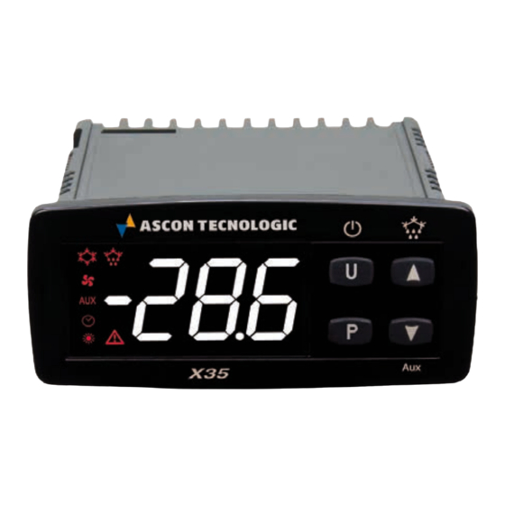
X35
DIGITAL ELECTRONIC
REFRIGERATION UNITS
CONTROLLER
OPERATING INSTRUCTIONS
21/11 - cod.: ISTR_M_X35-_E_00_--
ASCON TECNOLOGIC S.r.l.
Viale Indipendenza 56, 27029 - VIGEVANO (PV) ITALY
Tel.: +39 0381 69871 - Fax: +39 0381 698730
http:\\www.ascontecnologic.com
info@ascontecnologic.com
PREFACE
This manual contains the information necessary for
m
the product to be installed correctly and also instruc-
tions for its maintenance and use; we therefore
rEcommend that the utmost attention is paid to the
following instructions and to save it.
This document is the exclusive property of Ascon Tecnologic
S.r.l. which forbids any reproduction and divulgation, even
partially, of the document, unless expressly authorized.
Ascon Tecnologic S.r.l. reserves the right to make any formal
or functional changes at any moment and without any notice.
Ascon Tecnologic S.r.l. and its legal representatives do not
assume any responsibility for any damage to people, things
or animals deriving from violation, wrong or improper use or
in any case not in compliance with the instrument features.
Whenever a failure or a malfunction of the device
m
may cause dangerous situations for persons, thing
or animals, please remember that the plant has to be
equipped with additional electromechanical devices
which will guarantee safety.
Ascon Tecnologic - X35- - OPERATING INSTRUCTIONS - PAG. 1
INDEX
1. Instrument description ............................................... 2
1.1
General description ........................................................... 2
1.2
Front panel description ..................................................... 2
2. Programming ............................................................... 2
2.1
Fast Set Point programming .............................................. 2
2.2
Standard mode parameters programming ........................ 3
2.3
Parameter Protection Using a Password .......................... 3
2.4
(parameters programming level) ....................................... 3
2.5
Reset parameters to default value .................................... 4
2.6
Keyboard lock function ...................................................... 4
2.7
Setting the current time and date ...................................... 4
2.8
2.9
Displaying HACCP alarms (models with RTC) ................. 5
3. Usage Warnings .......................................................... 5
3.1
Admitted usage ................................................................. 5
4. Installation warnings ................................................... 5
4.1
Mechanical mounting ........................................................ 5
4.1.1
Mechanical dimensions [mm] ............................................... 6
4.1.2
Panel cut-out ......................................................................... 6
4.1.3
Mounting ............................................................................... 6
4.2
Electrical connections ....................................................... 6
4.2.1
Electrical wiring diagram ....................................................... 6
5. Functions ..................................................................... 7
5.1
ON/Stand-by function ........................................................ 7
5.2
Normal, Eco and Turbo operating modes.......................... 7
5.2.1
"Normal/Eco" mode operation............................................... 7
5.2.2
Turbo/Normal/Eco mode operation ....................................... 7
5.4
Digital Inputs ..................................................................... 8
5.5
Outputs and buzzer configuration ..................................... 9
5.6
Temperature control ........................................................ 10
5.7
5.8
Defrost control ................................................................. 11
5.8.1
Starting automatic defrosts ................................................. 12
5.8.2
Manual defrost .................................................................... 13
5.8.3
Defrost ends ....................................................................... 13
5.8.4
Defrosts in event of evaporator probe error ........................ 14
5.8.5
Defrost display lock ............................................................. 14
5.8.6
Pre- and post-defrost output ............................................... 14
5.8.7
Hot-gas defrost in centralized systems ............................... 14
5.9
Evaporator fans control ................................................... 15
5.10 Alarm functions ............................................................... 16
5.10.1 Temperature alarms ............................................................ 16
5.10.2 External alarms (digital inputs) ........................................... 17
5.10.3 Open door alarm................................................................. 17
5.11 HACCP function (alarm recording) ................................. 17
5.11.1 HACCP temperature alarms ............................................... 18
5.11.2 HACCP power failure alarms (black-out) ............................ 18
5.11.3 HACCP alarms from digital input ........................................ 18
5.13 Clock programmable events ............................................ 19
5.14 RS485 Serial Interface .................................................... 19
6. Accessories ............................................................... 20
6.1
6.2
Parameters configuration using an NFC Device ............. 20
6.3
TVR Y remote display ..................................................... 20
7. Programmable parameters table .............................. 21
8. Problems and maintenance ...................................... 27
8.1
Notifications .................................................................... 27
8.1.1
Error messages .................................................................. 27
8.1.2
Other messages ................................................................. 27
8.2
Cleaning .......................................................................... 27
8.3
Disposal .......................................................................... 27
9. Warranty and Repairs ............................................... 27
10. Technical data ............................................................ 27
10.1 Electrical characteristics ................................................. 27
10.2 Mechanical characteristics .............................................. 28
10.3 Functional features ......................................................... 28
11. How to order .............................................................. 28
/Aux ................................ 18
Advertisement
Table of Contents

Related Manuals for Ascon tecnologic X35


Summary of Contents for Ascon tecnologic X35
-
Page 1: Table Of Contents
9. Warranty and Repairs ..........27 10. Technical data ............27 10.1 Electrical characteristics ..........27 10.2 Mechanical characteristics ..........28 10.3 Functional features ............28 11. How to order .............. 28 Ascon Tecnologic - X35- - OPERATING INSTRUCTIONS - PAG. 1... -
Page 2: Instrument Description
Aux output, etc. (see functions of keys SPE alternated to its value ready for changes; /Aux). – To modify the Eco Set Point, press the keys to in- Ascon Tecnologic - X35- - OPERATING INSTRUCTIONS - PAG. 2... -
Page 3: Standard Mode Parameters Programming
If t. H A = 1 the parameters related to stored HACCP alarms The password protection can be disabled setting t. P P = oF. Ascon Tecnologic - X35- - OPERATING INSTRUCTIONS - PAG. 3... -
Page 4: Reset Parameters To Default Value
Decrease Decrease value value y. + 2 digits for the current year (e.g.: y. 1 0); M. + 2 digits for the and current month (e.g.: M. 0 5); Ascon Tecnologic - X35- - OPERATING INSTRUCTIONS - PAG. 4... -
Page 5: Displaying Haccp Alarms (Models With Rtc)
5 s relays, relays, solenoid valves, etc. while viewing one of the alarm data. Similarly, it is possible to reset the value of the H. d L param- Ascon Tecnologic - X35- - OPERATING INSTRUCTIONS - PAG. 5... -
Page 6: Mechanical Dimensions [Mm]
16 (9) A 10 (4) A 12 A Res. 30 LRA / 5 FLA Out2: 8 (3) A 4 (4) A 10 A Res. Out3,4: 5 (1) A 2 (1) A 2 A Gen.Use Ascon Tecnologic - X35- - OPERATING INSTRUCTIONS - PAG. 6... -
Page 7: Functions
However, Turbo mode is ap- plied automatically to restore product temperature at the end of Eco mode. Ascon Tecnologic - X35- - OPERATING INSTRUCTIONS - PAG. 7... -
Page 8: Digital Inputs
1 F and i. 2 F and whose but it is also possible to assign it temperature alarms action can be delayed by the time period set with parameters (possible usages: product, antifreeze probe, etc.); Ascon Tecnologic - X35- - OPERATING INSTRUCTIONS - PAG. 8... -
Page 9: Outputs And Buzzer Configuration
(r. H C = nr); 14 External LP alarm signal and ot output disabled by NO Controls the second defrost device; contact: at input closure the instrument deactivates the Ascon Tecnologic - X35- - OPERATING INSTRUCTIONS - PAG. 9... -
Page 10: Temperature Control
2 The buzzer is activated briefly only to signal the keys pressure (it does not signal alarms); 3 The buzzer is activated both to signal the alarms and the keys pressure. Ascon Tecnologic - X35- - OPERATING INSTRUCTIONS - PAG. 10... -
Page 11: Compressor Protection Function And Power-On Delay
Et With electrical heating and defrosting temperature control: while defrosting, the ot output is disabled while the output dF operates as evaporator tempera- Ascon Tecnologic - X35- - OPERATING INSTRUCTIONS - PAG. 11... -
Page 12: Starting Automatic Defrosts
ON. This mode the one currently used in the for the reduction happen. refrigerators systems; If parameter d. d d = 100%, at first increasing (> 1°) of the DT Ascon Tecnologic - X35- - OPERATING INSTRUCTIONS - PAG. 12... -
Page 13: Manual Defrost
However, the end of a defrost as a controller phase always defrosts are disabled occurs when both times have elapsed. If instead the evaporator probe is used, the defrost cycle Ascon Tecnologic - X35- - OPERATING INSTRUCTIONS - PAG. 13... -
Page 14: Defrosts In Event Of Evaporator Probe Error
E relative to evaporator 1 (d. d 2 remains at the same sors, being centralized, are not controlled by the instrument value even if the probe configured as 2P is in error). (to adjust the temperature the instrument controls the Liquid Ascon Tecnologic - X35- - OPERATING INSTRUCTIONS - PAG. 14... -
Page 15: Evaporator Fans Control
F. t F (fan deactivation time). If the defrost request occurs when the Liquid valve When ot output is switched OFF, the instrument activates the Ascon Tecnologic - X35- - OPERATING INSTRUCTIONS - PAG. 15... -
Page 16: Alarm Functions
1, o. o 2, o. o 3 and o. o 4 A. d A, alarm 1 is disabled, whereas during defrosts according to the parameters set. alarm 2 is always enabled. Ascon Tecnologic - X35- - OPERATING INSTRUCTIONS - PAG. 16... -
Page 17: External Alarms (Digital Inputs)
If the alarm is still active at the time it is displayed, the data are shown but the alarm is not recognized and cannot be cancelled. In the event of unrecognized (and therefore still ongoing) Ascon Tecnologic - X35- - OPERATING INSTRUCTIONS - PAG. 17... -
Page 18: Functioning Of Keys
Real Time Clock the action of the If A. b o = oF the black-out alarm is never recorded. keys force output status until the next event; Ascon Tecnologic - X35- - OPERATING INSTRUCTIONS - PAG. 18... -
Page 19: Clock Programmable Events
1 = 9600 baud, 2 - 19200 baud, 3 - 38400 baud. manually to Normal mode it will stay in Normal mode until the next event that switches it to Eco mode. Ascon Tecnologic - X35- - OPERATING INSTRUCTIONS - PAG. 19... -
Page 20: Accessories
From/To the instruments. The TVR Y (--) AFC1 is powered directly by the USB port through which is connected to a PC. For additional info, please look at the TVR Y instruction manual. Ascon Tecnologic - X35- - OPERATING INSTRUCTIONS - PAG. 20... -
Page 21: Programmable Parameters Table
0 = oF oF Delay disabled 2813 Delay in acquiring digital input DI2 i. 2 t 0.01 ÷ 99.59 (min. s) 0.01 ÷ 9.59 (min.s) ÷ 99.5 (min.s x 10) Ascon Tecnologic - X35- - OPERATING INSTRUCTIONS - PAG. 21... - Page 22 2 evaporator 2 0.01 ÷ 99.59 (min.s) 0.01 ÷ 9.59 (min.s) ÷ 99.5 (min.s x 10) Defrost stop temperature 2829 - 99.9 ÷ 999 °C/°F d. t 2 evaporator 2 Ascon Tecnologic - X35- - OPERATING INSTRUCTIONS - PAG. 22...
- Page 23 Min. alarm disabled 283E Low temperature Alarm 1 threshold A. L 1 -99.9 ÷ 999°C/°F -99.9 ÷ 999 °C/°F 283F Alarms A.H1 and A.L1 Hysteresis) 0.0 ÷ 30.0°C/°F A. d 1 Ascon Tecnologic - X35- - OPERATING INSTRUCTIONS - PAG. 23...
- Page 24 Time relative to auxiliary 0 = oF oF Time relative to auxiliary output disabled 2856 o. t u output 0.01 ÷ 99.59 (min.s) 0.01 ÷ 9.59 (min.s) ÷ 99.5 (min.s x 10) Ascon Tecnologic - X35- - OPERATING INSTRUCTIONS - PAG. 24...
- Page 25 Year (10 ÷ 99) c. d t (#) 2863 Current date b7 ÷ b10 = Month M Month (1 ÷ 12) b11 ÷ 15 = Day date Day date (1 ÷ 31) Ascon Tecnologic - X35- - OPERATING INSTRUCTIONS - PAG. 25...
- Page 26 0.01 ÷ 9.59 (min. s) ÷ 99.5 (min.sx10) 0 = oF oF Dealy disabled 2892 Post-defrost delay d. P d 0.01 ÷ 99.59 (min. s) 0.01 ÷ 9.59 (min. s) ÷ 99.5 (min.sx10) Ascon Tecnologic - X35- - OPERATING INSTRUCTIONS - PAG. 26...
-
Page 27: Problems And Maintenance
Reinforced insulation between the low voltage section (type waste disposal. H supply type and relay outputs) and the extra low voltage section (inputs), Reinforoced between power supply and relay outputs. Ascon Tecnologic - X35- - OPERATING INSTRUCTIONS - PAG. 27... -
Page 28: Mechanical Characteristics
1 kV inputs; EN61000-4-5: sup- ply 2KV com. mode, 1 kV\ diff. mode; EN61000-4-6: 3V) Regulation 37/2005/CE (EN13485 air/air, S, A, 1, -50°C +90°C with probe NTC 103AT11 or Pt1000 clas B or better). Ascon Tecnologic - X35- - OPERATING INSTRUCTIONS - PAG. 28...
Need help?
Do you have a question about the X35 and is the answer not in the manual?
Questions and answers