Table of Contents
Advertisement
ISO 9001
C e r t i f i e d
Ascon Tecnologic srl
viale Indipendenza 56, 27029 Vigevano (PV)
Tel.: +39-0381 69 871 - Fax: +39-0381 69 8730
Sito internet: www.ascontecnologic.com
Indirizzo E-Mail: sales@ascontecnologic.com
Process controller
with PROFIBUS DP
and Modbus Master/Slave
1
/
DIN - 48 x 96
8
X5 line
U s e r m a n u a l • 0 9 / 0 9 • C o d e : I S T R _ M _ X 5 _ E _ 0 5 _ - -
c
c
Advertisement
Table of Contents

Related Manuals for Ascon tecnologic X5 Series


Summary of Contents for Ascon tecnologic X5 Series
- Page 1 U s e r m a n u a l • 0 9 / 0 9 • C o d e : I S T R _ M _ X 5 _ E _ 0 5 _ - - C e r t i f i e d Ascon Tecnologic srl viale Indipendenza 56, 27029 Vigevano (PV) Tel.: +39-0381 69 871 - Fax: +39-0381 69 8730...
- Page 2 Process controller with PROFIBUS DP and Modbus Master/Slave DIN - 48 x 96 X5 line I 1 I 2 I 3 45. 8 0 45. 8 0...
- Page 3 Information Please, read carefully these instructions before proceeding with the installation of the controller. Class II instrument, real panel mounting. OTES This controller has been designed with compliance to the European Directives. ON ELECTRIC Consult Declaration of Conformity for further details on Directives and Standards used for SAFETY AND Compliance.
-
Page 4: Table Of Contents
Table of contents TABLE OF CONTENTS INTRODUCTION DISPLAYS page page ................................................page RODUCT ODING ..................COMMANDS page ........................INSTALLATION page page OMMANDS FROM EYBOARD ..................................page page ESCRIPTION OMMANDS FROM IGITAL NPUTS ..............................page OPERATING CONDITIONS OMMANDS FROM ERIAL COMMUNICATION ................ -
Page 5: Introduction
OP2 OP3 OP4 Double The process controllers of the action OP5 OP2 OP1 OP3 OP4 X5 series have been designed OP5 OP6 OP1 OP2 OP3 OP4 for the industrial environment, are provided with a complete Valve OP1 OP2 OP3 OP4 OP5 OP6... - Page 6 1 - Introduction Line Basic model Accessories 1.1 MODEL CODE Model: – – The complete code is displayed Basic product code Power Supply Colour on the instrument label. Outputs User manual Setpoint The information about product Serial + mathematical package (MP) Options coding are accessible from the front panel by mean of a partic-...
-
Page 7: Installation
2 - Installation INSTALLATION 2.1 GENERAL DESCRIPTION IP 20 Terminal Block EN61010 - 1 (IEC1010 - 1) Installation must only be carried out by qualified personnel. Panel surface Before proceeding with the installation of this controller, follow the instructions illus- trated in this manual and, particularly the installation precautions marked with the symbol, related to the European... - Page 8 2 - Installation 2.1.1 DIMENSIONAL DETAILS 2.1.2 PANEL CUT-OUT mm min 1.89 2.56 in min 3.78 mm max. mm max. 0.39 0.39 in max. in max. 4.33 +0.6 mm 1.78 +0.023 in...
- Page 9 2 - Installation 2.2 ENVIRONMENTAL RATINGS Operating conditions Altitude up to 2000 m Temperature 0…50°C [1] Relative humidity 5…95 % non-condensing Special conditions Suggestions Altitude > 2000 m Use 24Vac supply version Temperature > 50°C Use forced air ventilation Humidity > 95 % Warm up Use filter Conducting atmosphere...
- Page 10 2 - Installation PANEL MOUNTING [1] 2.3.1 INSERT 2.3.2 INSTALLATION 2.3.3 CLAMPS 2.3.4 INSTRUMENT THE INSTRUMENT SECURING REMOVING UNPLUGGING 1 Prepare panel cut-out; 1 Fit the mounting clamps; 1 Insert the screwdriver in the 1 Push and 2 Check front panel gasket 2 Push the mounting clamps clips of the clamps;...
-
Page 11: Electrical Connections
3 - Electrical Connections ELECTRICAL 3.1 TERMINAL BLOCK [1] CONNECTIONS Rear 5.7 mm terminal 0.22 in cover Cable size 1 mm 35 screw terminals M3 Option terminals Holding screw 0.5 Nm (option) Positive screw-driver PH1 22 N/C (option) Negative screw-driver 24V—... - Page 12 3 - Electrical Connections PRECAUTIONS 3.2 SUGGESTED WIRES ROUTING Despite the fact that the instru- ment has been designed to work Conduit for supply and output cables in an harsh and noisy environ- mental (level IV of the industrial standard IEC 801-4), it is recom- mended to follow the following suggestions.
- Page 13 3 - Electrical Connections 3.3 EXAMPLE OF WIRING DIAGRAM (VALVE CONTROL) Retransm. Commands Supervisory Notes: 1] Make sure that the power supply voltage is Power supply the same indicated on the instrument. switch 2] Switch on the power supply only after that RS485 all the electrical connections have been completed.
- Page 14 3 - Electrical Connections 3.3.1 POWER SUPPLY 3.3.2 PV CONTROL INPUT Switching power supply with mul- A L-J-K-S-R-T-B-N-E-W thermocouple type tiple isolation and PTC protection. • Connect the wires with the polarity as shown; • Use always compensation cable of the correct type •...
- Page 15 3 - Electrical Connections 3.3.2 PV CONTROL INPUT 3.3.3 PV CONTROL INPUT - IN2 FREQUENCY INPUT C For mA, mV C1 With 2 wires transducer Using the frequency input (IN2), the IN1 input is not yet avail- able Transmitters 10kΩ V, mV mA 24Vdc •...
- Page 16 3 - Electrical Connections 3.3.4 AUXILIARY INPUT 3.3.5 DIGITAL INPUT Isolated • The input is active when the A - From Remote Setpoint B- From Potentiometer o.c. o.c. contact logic state is ON, corre- Current 0/4…20mA; for the measure of the position sponding to the contact Com.
- Page 17 3 - Electrical Connections 3.3.6 OP1 - OP2 - OP3 - OP4 - OP5 - OP6 OUTPUTS (OPTION) The functionality associated to Control outputs Alarms Retransmission each of the OP1, OP2, OP4, Main Secondary OP5 and OP6 output is defined PV / SP / OP (Heat) (Cool)
- Page 18 3 - Electrical Connections 3.3.6-A SINGLE ACTION RELAY 3.3.6-C DOUBLE ACTION (TRIAC) CONTROL OUTPUT RELAY (TRIAC)/RELAY (TRIAC) CONTROL OUTPUT Fuse Fuse Coil of the heat Coil of the heat load contactor load contactor Fuse Coil of the cool load contactor 3.3.6-B1 SINGLE ACTION SSR DRIVE 3.3.6-D1 DOUBLE ACTION CONTROL OUTPUT...
- Page 19 3 - Electrical Connections Notes for pages 17 - 18 - 19 3.3.6-E1 DOUBLE ACTION OP1 - OP2 Relay output DIGITAL/RELAY (TRIAC) CONTROL OUTPUT • SPST Relay N.O., 2A/250 Vac (4A/120Vac) for resistive load, Static Relay • Fuse 2AT at 250V, 4AT at 110V. OP1 - OP2 Triac output Fuse Heat...
- Page 20 3 - Electrical Connections 3.3.6-F2 DOUBLE ACTION CONTROL OUTPUT 3.3.6-G MOTOR POSITIONER OUTPUT DIGITAL / ANALOGUE RELAY (TRIAC)/RELAY (TRIAC) Valve drive PID without potentiometer Static 3 pole output with N.O. contacts Relay V, mV (increase, decrease, stop) Cool load Heat load Increase 3.3.6-F3 DOUBLE ACTION CONTROL OUTPUT...
- Page 21 3 - Electrical Connections 3.3.7 OP1-2-3-4 ALARM OUTPUTS 3.3.8 OP5 AND OP6 (OPTION) 3.3.9 SERIAL COMMUNICATIONS ANALOGUE CONTROL OUTPUTS (OPTION) [2] Fuse MASTER SLAVE mA mV, V AL3 load Heat load AL3 load Fuse V, mV Fuse • Galvanic isolation 500Vac/1 min; Cool Compliance to the EIA RS485 standard load...
- Page 22 3 - Electrical Connections 3.3.10 PROFIBUS DP (OPTION) Termination resistors 220Ω and To make the connections easier, a D-Sub type (9 poles) connec- 390Ω ( W, ±5%) for external tor: model AP-ADP-PRESA-DSUB/9P mounting on the initial and end- Must be used with a 9PIN male ERNI type part no. 103648 or sim- ing PROFIBUS stations only.
-
Page 23: Operations
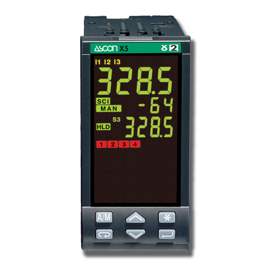
4 - Operation OPERATION 4.1.1 KEY FUNCTIONS AND DISPLAYS IN OPERATOR MODE Over Under Digital input status LEDs (yellows) - IL1 active range range ó - IL2 active 8888 ____ 8888 ---- ò - IL3 active ô I 1 I 2 I 3 PV control input in engineering units 45. -
Page 24: Keys Functions And Display
4 - Operation 4.1.2 KEYS FUNCTIONS AND DISPLAY IN PROGRAMMING MODE The parameter setting procedure has a timeout. If no keys are Parameter value 35. 0 pressed for, at least, 30 seconds, the controller switches back, automatically, to the operator mode. - Page 25 4 - Operation 4.2 PARAMETER SETTING 4.2.1 NUMERIC ENTRY 4.2.2 MNEMONIC CODES SETTING 274. 8 Operator mode (i.e. the modification of the Setpoint (e.g. configuration see page 26) 275. 0 working Setpoint Press the to display the next or previous mnemonic value from 275.0 to 240.0 ) displayed for the selected parameter.
- Page 26 4 - Operation CONFIGURATION PROCEDURE Enter the configuration password 274. 8 Conf Operator Configuration from -999...9999 Mode menu (33 default from factory) 275. 8 Menu C. p as Must be equal to the value of the parameter C. P as (see page.50) Press the key until Back to the operator mode...
- Page 27 4 - Operation 4.3.1 INPUTS CONFIGURATION Tab. 1 Input type Tab. 2 Engineering units InP. LINEAR INPUT Value Description Value Description é I nP. PInp. é U nit ONLY 0…600°C 32…1112°F None tc. j none Conf 0…1200°C 32…2192°F Degree centigrade tc.
- Page 28 4 - Operation 4.3.2 SETPOINT CONFIGURATION Tab. 3 Setpoint type S. P . Value Description é S . P . t y Local only Remote only Conf Local/remote only REMOTE Local - trim INPUT ONLY loc. t Remote - trim reM.
- Page 29 4 - Operation 4.3.3 OUTPUT CONFIGURATION WITH OP5 ANALOGUE WITH OP6 ANALOGUE OUTPUT é OUTPUT NOT USED AS MAIN NOT USED AS SECONDARY C. O P. 5 Cool output on OP5 CONTROL OUTPUT CONTROL OUTPUT Conf (Heat/Cool only) é O FF é...
- Page 30 4 - Operation RETRANSMISSION When OP5 and OP6 outputs Retransmission high range Tab. 5 Control mode Tab. 7 Secondary output (Cool) are not configured as control Value Description Value Description é C n. t y # r t. H 1 é...
- Page 31 4 - Operation 4.3.4 DIGITAL INPUTS CONFIGURATION 4.3.5 ALARM S CONFIGURATION é O FF L. i np Digital Inputs AL1 alarm type Tab. 10 AL. 1 see table 11 Functions Conf é I l1 Conf Value Description é I l2 é...
- Page 32 4 - Operation Tab. 11 Alarm type é O FF é O FF é O FF AL2 alarm type AL3 alarm type AL4 alarm type é A l 1 AL. 2 AL. 3 AL. 4 see table 11 see table 11 see table 11 é...
- Page 33 4 - Operation 4.3.6 AL1, AL2, AL3, AL4 ALARMS CONFIGURATION [A] OPERATING [B] ALARM ACKNOWLEDGE CONDITIONS FUNCTION It is possible to configure up to 4 The alarm, once occurred, is pre- Alarm occurrence display alarms: AL1, AL2, AL3, AL4 (see This function can be enabled by the sented on the display until to the time Absolute alarm...
- Page 34 4 - Operation [C] START-UP DISABLING [D] ALARM DISABLING AT SENSOR BREAK LOOP BREAK ALARM LBA For those alarm that are configured to be different than LBA, is possible to When the controller connection to set the parameter # d onb (disable on break).
- Page 35 4 - Operation PARAMETERISATION - MAIN MENU 274. 8 Operator mode 275. 0 The parameter setting procedure has a timeout. If no keys are pressed for, at least, 30 seconds, the controller switches back, auto- matically, to the operator mode. Setpoint programmer menu (if the option is installed)
- Page 36 4 - Operation After having selected the parameter or the code, press $ or % to modify the value (see page 24) The value is entered when the next parameter is selected, by pressing the è key. Pressing í go back to the Operator mode Input Output Communication...
- Page 37 4 - Operation é L oc S. P . 4.4.1 PARAMETERISATION - SETPOINT MENU Setpoint menu Setpoint selection Depending on the configuration index shown on page 27, the Menu local/remote following parameters are present or not. [1] The units of the slope parameters are digit/s, digit/min digit/h é...
- Page 38 4 - Operation 4.4.2 PARAMETERISATION - ALARMS MENU [1] A code, specifying the number é é and the alarm type that has been Alarms menu configured (see page 31), is Alarm 1 hysteresis Alarm 3 hysteresis hy. I u hy. 3 u displayed.
- Page 39 4 - Operation 4.4.3 PARAMETERISATION - PID MENU (not shown for ON-OFF control action) Menu Menu é é é O FF é Proportional Error Proportional band P. b . d. E rr P. b . C band dead band Cool channel 0.5…999.9%c.s.
-
Page 40: Parameterisation
4 - Operation 4.4.4 PARAMETERISATION TUNING MENU 4.4.5 PARAMETERISATION (not shown for ON-OFF control action) INPUT MENU for AT Tune Tuning Input menu menu # N o Menu Menu # y eS Calculated Proportional p. b . band [1] (display only) (available when adaptive tune is selected) é... - Page 41 4 - Operation 4.4.6 PARAMETERISATION - OUTPUT MENU é 10:0 Output Cycle time t. c . (time proportional only) menu 0.2…100.0 s Menu é Control Output low limit Valve drive Heat / Cool OP. L (not available in algorithm Algorithm Heat/Cool configuration) 0…100% é...
- Page 42 4 - Operation CoMM 4.4.7 PARAMETERISATION - SERIAL COMMUNICATION MENU Serial Menu Depending on serial communication choosen (see model code on page 5), there are the communication following parameters: menu Index RS485 Modbus/Jbus c= 7-8 SLAVE + PROFIBUS DP é Add.
-
Page 43: Parameters
4 - Operation PARAMETERS 4.5.1 SETPOINT MENU For a simpler use of the con- Otherwise, the Setpoint value is 1st stored Setpoint # S . P . 1 # S . P . L troller, its parameters have been reached according to the con- Setpoint low limit organised in menu, according to... - Page 44 4 - Operation Remote Setpoint Bias and Ratio Stored Setpoint # S . P . t r Remote # r tio Remote Setpoint Ratio tracking signal (see chapter 4.3.2 at page 27) Ratio is the coeff. which defines Two different operation mode the remote Setpoint span with bias = 20 can be set:...
- Page 45 4 - Operation 4.5.1 SETPOINT MENU 4.5.2 ALARM MENU (see also pages 32 and 33) If SR starting point is lower Setpoint (table 3, page 27) reM. t then the ending point, both SP = REM + (rtio • SL) + bias Asymmetric Alarm expressed in engineering units:...
- Page 46 4 - Operation 4.5.3 PID MENU 4.5.4 TUNING MENU (not shown for ON-OFF main control output) Not present with On-Off main Derivative Manual # t . d . # M . r es Time reset output. See page also 57 This term specifies the value of Cool Derivative # t .
- Page 47 4 - Operation 4.5.4 TUNING MENU (Cont.) Natural frequency Fuzzy-Tuning is selected when, The self-learning adaptive auto- amplitude of the signals. On the at the start of the autotune oper- tune is not intrusive. It doesn’t basis of this data and their sta- tuning start ation, the PV is far from the affect the process, at all, during...
- Page 48 4 - Operation 4.5.5 INPUT MENU 4.5.6 OUTPUT MENU Input Control output Control output Soft start # O p. h y # O p. H # s t. t M # t . f il filter high limit time hysteresis Time constant, in seconds, of This value specifies the time the Cool output...
- Page 49 4 - Operation E.g.: Cn. t y - sp. l 1 Split Range % SPL3 Heat/Cool # s p. l t # d . b nd (split range only) MCop = 4...20 (OP5) deadband Physical This parameter specifies the The value set as SP. L t sCop = 4...20 (OP6) output Secondary...
- Page 50 4 - Operation 4.5.7 SERIAL COMMUNICATION MENU (OPTION) SLAVE address C - PROFIBUS DP SLAVE # A dd. S Three serial comm.s options 45. 8 0 communication (Process Field bus protocol) - 1…247 45. 8 0 MASTER are available: Industrial standard for peripheral SLAVE Profibus # A dd.
- Page 51 4 - Operation PARAMETERISATION - ACCESS MENU - PASSWORD - CALIBRATION 274. 8 [1] With the level of access set to full, Pressing í all the related parameters are dis- Operator go back to the Operator mode played. mode 275. 8 Press until fUll Oper...
- Page 52 4 - Operation 45. 8 0 45. 8 0 During the up-download of the data to/from the Memory chip, the controller Edit C. p ot display shows the segment clockwise Access Calibrate rotation of the digits. the potentiometer to the edit level Ac.
-
Page 53: Access Levels
4 - Operation PARAMETERISATION - ACCESS MENU - PASSWORD - CALIBRATION The parameters in the access Group of parameters Code Access level fast With the access level Edit, the level are recalled on the Visible read user defines which groups and front panel through the pro- Not visible Hide... -
Page 54: Displays
5 - Displays DISPLAYS 5.1 STANDARD DISPLAY FAST VIEW (fast access to the parameters) Manual Operator mode 274. 8 274. 8 mode Automatic mode With this procedure, simple and fast, up to 10 parameters, select- 275. 0 275. 0 ed through the fast view (see par 4.6 page 52) are displayed and Engineering 274. - Page 55 6 - Commands COMANDS COMMANDS TO THE CONTROLLER AND OPERATING PHASES The commands can be entered in 3 ways: 6.1 KEYPAD 6.2 DIGITAL INPUTS 6.3 SERIAL see page 55 see page 58 COMMUNICATIONS see the manual on this topic • Setpoint modification •...
- Page 56 6 - Commands 6.1 KEYPAD COMMANDS 6.1.1 SETPOINT MODIFICATION 6.1.2 AUTO/MANUAL MODE The Setpoint is directly modi- 274. 8 274. 8 274. 8 Select Operator manual mode fied with the $% keys. Operator green (automatic) Once entered, the new value is mode checked and becomes operating 275.
- Page 57 6 - Commands 6.1.3 LOCAL/ REMOTE SELECTION 6.1.4 STORED SETPOINTS SELECTION (see also pages 42, 43) 274. 8 The Setpoint is directly modified with the $% keys. S. P . Once entered, the new value is checked and becomes operating after 2 seconds.
- Page 58 6 - Commands 6.1.5 TUNE RUN / STOP This controller is provided with 2 different Tuning algorithm: Press until • Fuzzy tune (one shot tune) Fuzzy Tune Adaptive Tune for calculating the optimal PID start-up start-up terms parameters • Adaptive Tune (continuous tune) for a continuous calculation of the PID terms parameters.
-
Page 59: Commands
6 - Commands DIGITAL INPUTS 6.2.1 DIGITAL INPUTS COMMANDS FOR LOCAL-REMOTE SETPOINT COMMANDS Performed operation Parameter Function Notes A function is assigned, through value the configuration procedure to # O FF None Not used each IL1, IL3 and IL3 digital —... - Page 60 7 - Programmed Setpoint PROGRAMMED PROGRAM STRUCTURE SETPOINT Ramp The program consists of a The program consists of: sequence of segments. • 1 initial segment named INTRODUCTION • 1 end segment named # s . p . = = When the Setpoint programmer For each segment, it is speci- •...
-
Page 61: Setpoint Programmer
7 - Programmed Setpoint EXAMPLE OF SETPOINT PROFILE 7.2 SETPOINT PROGRAMMER 7.2.1 MAXIMUM # s p. 4 # s p. 9 °C Setpoint # s p. 1 0 Maximum ALLOWED allowed deviation # s p. 3 b b a a n n d d DEVIATION ( # s p. - Page 62 7 - Programmed Setpoint OPERATION 7.2.2 RE-START OF A PROGRAM AFTER A POWER FAILURE A. Ramp # b and # C ont # r aMp The parameter . spec- # f ail is selected, is selected, ifies the behaviour of the pro- the execution of the program the execution of the program grammer at power up (see page...
-
Page 63: Parameterisation - Program Menu
7 - Programmed Setpoint PARAMETERISATION - PROGRAM MENU (OPTION) 274. 8 Prog Operator Program mode menu 275. 8 Menu Program number Program status No. of segments Pr. n o Stat n. S eg 1…14 max = reset Hold = hold = start Restart No. - Page 64 7 - Programmed Setpoint Continue for Segment 0 Segment 1 ti. 0 ti. 1 all the 14 normal time time segments Unit Unit 0.1…999.9 0.1…999.9 Segment 0 Segment 1 s. P . 0 s. P . 1 s. P . f Setpoint Setpoint segment Setpoint...
-
Page 65: Program Status Displaying
7 - Programmed Setpoint PROGRAM STATUS DISPLAYING The function mode of the program as well On program run mode, each 3 s the display its status is displayed clearly by means the shows alternatively: ; leds as follows: - number of running program; Ö... - Page 66 7 - Programmed Setpoint START/STOP OF A PROGRAM The various commands, sup- Type of Local Programmed Programmed The different phase are dis- operating ported by the controller, are dif- played in a chained way, just for setpoint ferent for each of the following easing the understanding of the Execution Hold...
- Page 67 7 - Programmed Setpoint ê 7.5.1 START/STOP OF A PROGRAM BY DIRECT MODE WITH Program selection 274. 8 Operator mode (local Setpoint) 275. 0 pr. n o Program Note: start To reset the program see pro- cedure at page 67 Program number dis- 274.
-
Page 68: Run
7 - Programmed Setpoint 7.5.2 START/HOLD/STOP OF A PROGRAM THROUGH THE PARAMETER MENU Reset procedure Program selection 274. 8 Operator mode (local Setpoint) Pr. n o Stat 275. 0 Program start Program Press until running HoLd Ö Prog Program continuously on Stat menu Menu... -
Page 69: Program
7 - Programmed Setpoint 7.5.3 DIGITAL INPUT COMMANDS FOR SETPOINT PROGRAMMER FUNCTION (OPTION) Performed operation Parameter Function Notes value — — None Not used # O FF Set manual mode Automatic Manual # A . M an With the keypad locked the commands from digital inputs and Keyboard lock Unlock Locked... -
Page 70: Technical Specifications
8 - Technical Specifications TECHNICAL SPECIFICATIONS Features Description at 25°C env. temp. From keypad or serial communication the - the type of Setpoint - the type and functionality of the alarms Total configurability user selects: - the type of control algorithm - control parameter values (see chapter 4.3 page 25) - the type of input... - Page 71 8 - Technical Specifications Features Description at 25°C env. temp. Remote Bias in engineering units and ± range Current: 0/4...20mA: Rj = 30Ω Setpoint Ratio: -9.99… +99.99 Not isolated Auxiliary inputs Voltage: 1... 5, 0... 5, 0... 10V: Rj = 300kΩ Local + Remote Setpoint accuracy 0.1% Potentiometer 100Ω...
- Page 72 8 - Technical Specifications Features Description at 25°C env. temp. PID with overshoot control/ON-OFF - PID with valve drive algorithm, for controlling motorised positioners Algorithm Proportional band (P) 0.5…999.9% Integral time (I) 1…9999 s Derivative time (D) 0.1…999.9 s OFF = O Error dead band 0.1…10.0 digit Overshoot control...
- Page 73 8 - Technical Specifications Features Description at 25°C env. temp. SPST Relay N.O., 2A/250Vac (4A/120Vac) for resistive load OP1-OP2 outputs Triac, 1A/250Vac for resistive load OP3 output SPDT relay N.O., 2A/250Vac (4A/120Vac) for resistive load OP4 output SPST relay N.O. 2A/250Vac (4A/120Vac) for resistive load Galvanic isolation : 500 Vac/1 min Analogue: 0/1...
- Page 74 8 - Technical Specifications Features Description at 25°C env. temp. 4 programs, 16 segments (1 initial and 1 end) From 1 to 9999 cycles or continuous cycling (Off) Programmable Setpoint (optional) Time values in seconds, minutes and hours Start, stop, hold, etc. activated from the keypad, digital input and serial communications Step response Fuzzy-Tuning type .
- Page 75 Warranty WARRANTY We warrant that the products will be free from defects in material and workmanship for 18 months from the date of delivery. The warranty above shall not apply for any failure caused by the use of the product not in line with the instructions reported on this manual.
- Page 76 Icons table ICONS TABLE Digital input connected functions Main universal input Digital input Thermocouple Isolated contact Auto/Manual Run, Hold, Reset and RTD (Pt100) NPN open collector program selection Delta Temp (2x RTD) TTL open collector PV hold Setpoint slopes mA and mV inhibition Setpoint Custom...
Need help?
Do you have a question about the X5 Series and is the answer not in the manual?
Questions and answers