Table of Contents
Advertisement
Quick Links
Advertisement
Table of Contents

Related Manuals for oventrop Regudis W-HTE


Summary of Contents for oventrop Regudis W-HTE
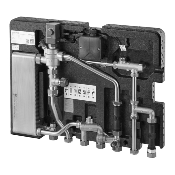
- Page 1 Regudis W-HTE Operating instructions Produktabbildung...
-
Page 3: Table Of Contents
Regudis W-HTE Contents Page General information ......................7 Validity of the instructions ........................7 Type plate ............................... 7 Scope of delivery ............................ 7 Contact ..............................7 Symbols used ............................7 Safety-related information ....................7 Normative directives ..........................7 Intended use ............................7 Modifications to the product ........................ - Page 4 Regudis W-HTE Contents Page Transport and storage ....................... 22 Installation ........................23 Notes on mounting ..........................23 Mounting options ..........................23 Mounting of the station and accessories in a cabinet ................23 6.3.1 Mounting of the cabinet ..........................23 6.3.2 Mounting of the ball valve connection set....................
- Page 5 Regudis W-HTE Contents Page Functional test of the check valve of the potable water circulation module ..........44 Leakage test (visual inspection) ......................44 Inspection of the electrical components and plug-in connections ............44 Performance test of the heat exchanger ....................45 Advice for the operator .....................46 10.1...
-
Page 7: General Information
The scope of delivery includes: translated from German. • Regudis W-HTE dwelling station Validity of the instructions • Operating instructions These instructions are valid for the Regudis W-HTE • Fixing material dwelling station. • Seal set Performance range 1 Contact Heat exchanger copper Item no. -
Page 8: Modifications To The Product
Regudis W-HTE Safety-related information Safety devices Any use beyond and/or different from this is considered improper use. Claims of any kind against the manufacturer and/or his 2.5.1 Automatic closing mechanism for the authorised representatives for damage resulting from control valve improper use cannot be recognised. -
Page 9: Danger To Life Due To Electric Current
Regudis W-HTE Safety-related information • 2.6.5 Risk of injury from pressurised Maintenance • components Removal and disposal Due to their professional training and experience as well Only carry out work on the heating circuit or as knowledge of the relevant standards, specialist sanitary,... -
Page 10: Availability Of The Operating Instructions
Regudis W-HTE Safety-related information 2.6.11 Availability of the operating instructions Every person who works with this product must have read and apply this manual and all applicable instructions (e.g. accessories instructions). The instructions must be available at the place of use of the product. -
Page 11: Technical Description
Regudis W-HTE Technical description 3. Technical description Design Fig. 3: Overview of the Regudis W-HTE dwelling station Spacer for heat meter Type plate Zone valve for heating circuit control Angled wall bracket Hot water temperature sensor Thermally insulated rear insulation shell... -
Page 12: Functional Description
Regudis W-HTE Technical description Functional description The Regudis W-HTE station is an electronically controlled product assembly intended for use in domestic areas. The product assembly provides heated potable water (hot water) within a residential unit and distributes the heating water (max. 90 °C) to radiators. With an optional flow temperature control module, heating water distribution to a surface heating system (e.g. -
Page 13: System Example With Cabinet
Regudis W-HTE Technical description System example with cabinet Actuator with integrated potable water temperature control Fig. 7: Actuator with integrated potable water temperature control Two-pole plug (power supply) Three-pole socket (volume flow sensor) Two-pole socket (hot water temperature sensor) Indicator light (LED) Error reset index (only for specialist tradespeople) Fig. -
Page 14: Installation Scheme
Regudis W-HTE Technical description Installation scheme Fig. 8: Installation scheme: dwelling station Radiator (heating circuit) Circulation circuit Dwelling station Hot water Ball valves Cold water Surface heating (heating circuit) Flow temperature control module for the surface heating system Primary return... -
Page 15: Technical Data
Regudis W-HTE Technical description Technical data Max. differential pressure 2.0 bar See charts in the General information Min. flow temperature appendix. Max. operating pressure p 10 bar Heating circuit (radiators) Max. operating 90 °C temperature t Fluid As in the primary circuit. - Page 16 Regudis W-HTE Technical description Seals EPDM and fibre materials Thermal insulation Expanded polypropylene Torques Union nuts G ¾ 45 Nm Union nuts G 1 45 Nm Spacers for meters ((6) and (11) in Fig. 3 on page 30 Nm Temperature sensor ((13) 15 Nm in Fig.
- Page 17 Regudis W-HTE Technical description Fig. 10: Connection assignment Hot water outlet Heating circuit return Heating circuit supply Primary supply from the buffer storage cylinder Primary return to the buffer storage cylinder Cold water outlet Cold water inlet from the house connection...
-
Page 18: Accessories And Spare Parts
Regudis W-HTE Accessories and spare parts 4. Accessories and spare parts Performance 1344093 range 1 Heat exchanger Accessories copper brazed, Performance 1344094 Sealix®- range 2 Designation Item no. protective layer Performance 1344095 Ball valve connection set 1344480 range 3 Ball valve connection set... - Page 19 Regudis W-HTE Accessories and spare parts Fig. 11: Spare parts Actuator with integrated potable water temperature control Power pack 100 - 240 V, ~50 - 60 Hz (in connection box) Volume flow sensor in a housing Sealing rings (5 pieces for junctions G ¾) Sealing rings (5 pieces for junctions G 1)
-
Page 20: Ball Valve Connection Set
Regudis W-HTE Accessories and spare parts Ball valve connection set Potable water circulation module Fig. 12: Ball valve connection set The ball valve connection set (item-no. 1344480) consists of ball valves for shutting off all connections of the station, which are pre-assembled in a bracket for a precise fit. -
Page 21: Flow Temperature Control Module (Only For Surface Heating Systems)
Regudis W-HTE Transport and storage Flow temperature control module 4.10 Stainless steel spacer (only for surface heating systems) Fig. 19: Stainless steel spacer Stainless steel spacer (item-no. 1349052) for replacing the plastic spacers for water meters and heat meters. 4.11 Front insulation shell Fig. -
Page 22: Installation
5.3.2. • Mount the station in a dry, frost-free room in which the ambient temperature does not exceed 35 °C Fig. 21: Preparation of the Oventrop cabinet during operation. • Cabinet Always mount the station upright, never inclined or lying down. -
Page 23: Mounting Of The Ball Valve Connection Set
Regudis W-HTE Installation 6.3.2 Mounting of the ball valve connection The ball valve connection set is mounted in the cabinet. 6.3.3 Mounting of heating circuit connection fittings for an additional direct heating circuit Only if you use an additional direct heating circuit in... -
Page 24: Mounting Of The Flow Temperature Control Module
Regudis W-HTE Installation cabinet at the top and onto the connections of the ball Pipework valves at the bottom. Bracket for the collector Align the station horizontally. Screw the station to the ball valves. Connections for the flow temperature control module Slide the washers onto the threaded bolts. - Page 25 Regudis W-HTE Installation position the station horizontally on the wall. Mark the drill holes through the holes (1) of the rear insulation shell and the angled wall bracket ((3) and (2) in Fig. 3 on page 11). Lift the station from the wall.
-
Page 26: Mounting Of The Heat Meter
Regudis W-HTE Installation Mounting of the heat meter The factory-fitted meter spacers are used for commissioning/pressure testing the station and are not suitable for continuous operation. If no meters are fitted, use the stainless steel spacers from the accessories range. -
Page 27: Mounting Of The Water Meter
Regudis W-HTE Installation supply. WARNING Screw the temperature sensor into the connection in Risk of injury from pressurised components! the primary supply. Media escaping under pressure can cause injuries. Slowly open the ball valves in the primary return (4) Only carry out installation work when the and primary supply (5). -
Page 28: Mounting Of The Potable Water Circulation Module (Optional)
Regudis W-HTE Installation CAUTION Have a cloth and a container ready to catch any water that escapes. Risk of burns on hot components! Touching hot components can cause burns. Close the ball valves in the cold water inlet (3) and cold Wear safety gloves. -
Page 29: Mounting Of The Derivative Temperature Control Set (Optional)
Regudis W-HTE Installation cold water outlet (7) and cold water inlet (6). Connect a hose line to the drain valve (see Fig. Open the vent valve (3) in the potable water circuit Fig. 3 on page 11 (3)) in the primary circuit to slightly. -
Page 30: Electrical Connection Of The Station
Regudis W-HTE Installation Electrical connection of the station Tighten any screw connections that are too loose. The derivative temperature control set is mounted. DANGER For setting the temperature, see paragraph 7.6 on Danger to life due to electric current! page 35. -
Page 31: Electrical Connection Of The Actuators And Of The Pump For The Surface Heating System (If Available)
Regudis W-HTE Installation If the potential equalisation of the station is not carried Contact thermostat out, e.g. by mounting it in an earthed cabinet, then mount an earthing clamp (Ø 18 mm) in the grey marked Observe the separate instructions for the pump, area (1) on the pipework of the station. -
Page 32: Commissioning
Regudis W-HTE Commissioning Cover Screws Loosen the screws (6) and remove the cover (5) of the connection box (3). Connect the power supply cable (1) to the prepared terminals (4) in the connection box. Screw the cover to the connection box. -
Page 33: Filling Of The Potable Water Circuit
Regudis W-HTE Commissioning CAUTION Connect a hose line to the drain valve (1) in the primary circuit to make it easier to direct escaping Risk of scalding due to hot media! water into a container. If the heating system has been in operation and the... -
Page 34: Setting Of The Ball Valves And Valves For Operation
Regudis W-HTE Commissioning (vertical). Primary return • The vent valve (4) and the drain valve (1) must be Primary supply closed. Set the heating system (e.g. pump and shutoff valves) CAUTION for operation of the station. Risk of scalding due to hot media! -
Page 35: Sliding Hot Water Temperature Control
Regudis W-HTE Commissioning Setting of the heating circuit 7.5.1 Sliding hot water temperature control temperature (if a flow temperature If the desired hot water temperature cannot be reached because the storage cylinder temperature is too low, the control module is available) temperature setting on the actuator for the hot water is automatically reduced to the max. -
Page 36: Troubleshooting
Regudis W-HTE Troubleshooting 8. Troubleshooting Troubleshooting table MALFUNCTION CAUSE REMEDY No heating of the potable water The volume flow sensor is Clean the volume flow sensor (see (only cold water at the draw-off contaminated or defective. paragraph 8.4 on page 40). If this does points). -
Page 37: Status Messages And Error Messages
Regudis W-HTE Troubleshooting MALFUNCTION CAUSE REMEDY The dwelling heating circuit does The filter insert in the primary supply Clean or replace the filter insert (see not get warm. is contaminated. paragraph 8.5 on page 42). The zone valve is mistakenly closed. -
Page 38: Status Messages
Regudis W-HTE Troubleshooting 8.2.1 Status messages Indicator light Description LED lights up green Normal operation, no hot water tapping. LED flashes green Normal operation, hot water tapping. LED lights up orange Calibration run or service run. LED lights up red Service mode active, actuator fully retracted. -
Page 39: Calcification Of The Heat Exchanger
Regudis W-HTE Troubleshooting on page 37) for longer than 5 seconds, the displayed CAUTION error is reset and a calibration run is started. As long as the rotary knob is set to the error reset index, a calibration run Risk of burns on hot components! of the actuator is started again and again, during which the Touching hot components can cause burns. -
Page 40: Inspection And Cleaning Of The Volume Flow Sensor
Regudis W-HTE Troubleshooting Ball valves The G 1 connection at the heat exchanger is intended for connection to the control valve. Heat exchanger Screw the heat exchanger to the pipework. Control valve with integrated differential pressure and volume flow control Mount the control valve (4) with actuator in the station. -
Page 41: Cleaning Of The Volume Flow Sensor
Regudis W-HTE Troubleshooting the indicator light flashes green • If the indicator light is permanently green during hot water tapping, the volume flow sensor may be contaminated. If the volume flow sensor is contaminated, then the volume flow of the cold water inlet or the cold water inlet with circulation pipe is not detected and no hot water tapping is registered. -
Page 42: Cleaning Of The Filter Insert
Regudis W-HTE Troubleshooting Hold the insertion turbine (1) under running water in Union nut the opposite direction to the flow direction to remove residues, such as hemp residues and to clean the insertion turbine. Screw the cap (2) tightly onto the circulation connection. -
Page 43: Maintenance
Regudis W-HTE Maintenance insert. CAUTION Clean the strainer under running water. Risk of scalding due to hot media! Check the housing for dirt residues and remove them During some work, the station has to remain in if necessary. operation and there is a risk of scalding due to unintentional escape of hot water or water steam. -
Page 44: Leakage Test (Visual Inspection)
Regudis W-HTE Maintenance Leakage test (visual inspection) Control valve with integrated differential pressure and volume flow control Due to the temperature fluctuations caused by operation, we recommend that you check the screw connections and Actuator with integrated potable water temperature seals annually for correct functioning. -
Page 45: Advice For The Operator
Regudis W-HTE Advice for the operator 10. Advice for the operator hot and cold water run for a short time at all draw-off points in order to exchange the potable water in the pipes. The operator must have himself instructed by the... -
Page 46: Disposal
Regudis W-HTE Removal and disposal CAUTION Risk of scalding due to hot media! Escaping hot media can lead to scalding. Close all ball valves at the station and depressurise the station. Allow the water in the station to cool down. -
Page 47: Appendix
Regudis W-HTE Appendix 12. Appendix 12.1 Characteristic line for heating mode Pressure loss during heating periods for performance ranges 1 to 3 -Heating circuit- Heating circuit volume flow [l/h] Fig. 56: Pressure loss during heating mode 134403082-V09.03.2022... -
Page 48: Characteristic Lines For Potable Water Mode
Regudis W-HTE Appendix 12.2 Characteristic lines for potable water mode Pressure loss during hot potable water preparation for performance ranges (PR )1 to 3 -Potable water circuit- 1500 1400 1300 1200 1100 1000 Hot potable water volume flow [l/min] Fig. 57:... - Page 49 Regudis W-HTE Appendix Pressure loss in the cold water outlet for performance ranges 1 to 3 Cold water volume flow [l/min] Fig. 59: Pressure loss in the cold water outlet 134403082-V09.03.2022...
-
Page 50: Characteristic Lines For Performance Range 1
Regudis W-HTE Appendix 12.3 Characteristic lines for performance range 1 Performance data according to SPF test procedure. Volume flow primary circuit at different flow temperatures -Heating of potable water from10 °C to 45 °C- 45°C 50°C 55°C 60°C 1000 9 10 11 12 13 14 15 16 17 18 19 20 21 22 23 24 25 26 27 28 29 30 Hot potable water volume flow [l/min] Fig. - Page 51 Regudis W-HTE Appendix Volume flow primary circuit at different flow temperatures -Heating of potable water from10 °C to 50 °C- 55°C 60°C 65°C 50°C 1000 9 10 11 12 13 14 15 16 17 18 19 20 21 22 23 24 25 26 27 28 29 30 Hot potable water volume flow [l/min] Fig.
- Page 52 Regudis W-HTE Appendix Volume flow primary circuit at different flow temperatures -Heating of potable water from10 °C to 55 °C- 1000 9 10 11 12 13 14 15 16 17 18 19 20 21 22 23 24 25 26 27 28 29 30 Hot potable water volume flow [l/min] Fig.
- Page 53 Regudis W-HTE Appendix Volume flow primary circuit at different flow temperatures -Heating of potable water from 10 °C to 60 °C- 65°C 70°C 60°C 75°C 1000 9 10 11 12 13 14 15 16 17 18 19 20 21 22 23 24 25 26 27 28 29 30 Hot potable water volume flow [l/min] Fig.
-
Page 54: Characteristic Lines For Performance Range 2
Regudis W-HTE Appendix 12.4 Characteristic lines for performance range 2 Performance data according to SPF test procedure. Volume flow primary circuit at different flow temperatures -Heating of potable water from10 °C to 45 °C- 45°C 55°C ° 50°C 1300 1200... - Page 55 Regudis W-HTE Appendix Volume flow primary circuit at different flow temperatures -Heating of potable water from10 °C to 50 °C- 65°C 60°C 50°C 55°C 1300 1200 1100 1000 9 10 11 12 13 14 15 16 17 18 19 20 21 22 23 24 25 26 27 28 29 30 Hot potable water volume flow [l/min] Fig.
- Page 56 Regudis W-HTE Appendix Volume flow primary circuit at different flow temperatures -Heating of potable water from10 °C to 55 °C- 65°C 70°C 60°C 55°C 1300 1200 1100 1000 9 10 11 12 13 14 15 16 17 18 19 20 21 22 23 24 25 26 27 28 29 30 Hot potable water volume flow [l/min] Fig.
- Page 57 Regudis W-HTE Appendix Volume flow primary circuit at different flow temperatures -Heating of potable water from10 °C to 60 °C- 70°C 65°C 75°C 60°C 1300 1200 1100 1000 9 10 11 12 13 14 15 16 17 18 19 20 21 22 23 24 25 26 27 28 29 30 Hot potable water volume flow [l/min] Fig.
-
Page 58: Characteristic Lines For Performance Range 3
Regudis W-HTE Appendix 12.5 Characteristic lines for performance range 3 Performance data according to SPF test procedure. Volume flow primary circuit at different flow temperatures -Heating of potable water from 10 °C to 45 °C- 50°C 45°C 1600 1500 55°C... - Page 59 Regudis W-HTE Appendix Volume flow primary circuit at different flow temperatures -Heating of potable water from10 °C to 50 °C- 55°C 50°C 1600 60°C 1500 1400 65° 1300 1200 1100 1000 10 11 12 13 14 15 16 17 18 19 20 21 22 23 24 25 26 27 28 29 30 Hot potable water volume flow [l/min] Fig.
- Page 60 Regudis W-HTE Appendix Volume flow primary circuit at different flow temperatures -Heating of potable water from 10 °C to 55 °C- 55°C 60°C 65°C 1600 1500 70° 1400 1300 1200 1100 1000 9 10 11 12 13 14 15 16 17 18 19 20 21 22 23 24 25 26 27 28 29 30 Hot potable water volume flow [l/min] Fig.
- Page 61 Regudis W-HTE Appendix Volume flow primary circuit at different flow temperatures -Heating of potable water from10 °C to 60 °C- 65°C 60°C 70°C 1600 1500 75°C 1400 1300 1200 1100 1000 9 10 11 12 13 14 15 16 17 18 19 20 21 22 23 24 25 26 27 28 29 30 Hot potable water volume flow [l/min] Fig.
-
Page 62: Advice Regarding Corrosion Protection
Valves, controls + systems Fresh water and dwelling stations Advice regarding corrosion protection The materials used in the Oventrop fresh water and dwelling The below table shows limit values of substances in potable stations are selected and processed in accordance with strict water when using heat exchangers with different brazing materials (copper, nickel or stainless steel). - Page 63 The specifying engineer and the user of the system are responsible for incorporating and evaluating substances and other factors in the water, which could influence corrosion and the formation of stones in the system. In critical water supply are- as, the local water authority should be consulted. OVENTROP GmbH & Co. KG Paul-Oventrop-Straße 1 D-59939 Olsberg...
-
Page 64: Eu Declaration Of Conformity
Regudis W-HTE Appendix 12.7 EU Declaration of conformity 134403082-V09.03.2022... - Page 65 Regudis W-HTE 134403082-V09.03.2022...
- Page 66 Regudis W-HTE 134403082-V09.03.2022...
- Page 68 Oventrop GmbH & Co. KG · Paul-Oventrop-Str. 1 · 59939 Olsberg Tel. +49 2962 820 · Fax +49 2962 82400 · mail@oventrop.com · www.oventrop.com...
Need help?
Do you have a question about the Regudis W-HTE and is the answer not in the manual?
Questions and answers