Table of Contents
Advertisement
Quick Links
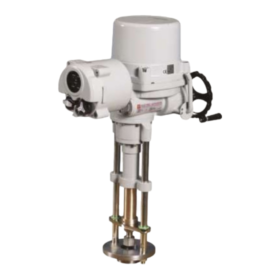
HL Series Electric Linear Actuator
Installation Operation & Maintenance Manual
HL Series Electric Linear Actuators
Installation, Operation & Maintenance Manual
Address : 26, Emtibeui 28-ro, Siheung-si, Gyeonggi-do, 15119, Republic of Korea
Tel : +82-31-488-8266, Fax : +82-31-488-8269, Home page : www.hkcon.co.kr, email : hkcon@hkcon.co.kr
Doc No. : HumG-HL-21 Rev2
Page 1 / 26
Valve Automation Leader, HKC
Advertisement
Table of Contents

Related Manuals for HKC HL Series


Summary of Contents for HKC HL Series
- Page 1 HL Series Electric Linear Actuator Installation Operation & Maintenance Manual HL Series Electric Linear Actuators Installation, Operation & Maintenance Manual Address : 26, Emtibeui 28-ro, Siheung-si, Gyeonggi-do, 15119, Republic of Korea Tel : +82-31-488-8266, Fax : +82-31-488-8269, Home page : www.hkcon.co.kr, email : hkcon@hkcon.co.kr Doc No.
-
Page 2: Table Of Contents
Actuator runs erratically ....................... 22 8.4. Optional Equipment(s)........................22 Installation and Maintenance Tips ..................... 22 APPENDIX Ⅰ. HL Series Coding System ..................23 APPENDIX II . Wiring Diagrams for Standard Models ..............24 Appendix III: Grounding ........................26 Doc No. : HumG-HL-21 Rev2... -
Page 3: Introduction
HL Series Electric Linear Actuator Installation Operation & Maintenance Manual 1. Introduction 1.1. Purpose The purpose of this manual is to introduce and explain the installation, operation and maintenance of HL-series electric actuators. This IOM Manual is distributed as a hard copy when delivered the ordered products to customer. -
Page 4: Initial Inspection
HL Series Electric Linear Actuator Installation Operation & Maintenance Manual 2.1.2. Applied Standard ① [IEC60079-0:2017(Ed.7.0 +IS01, EN60079-0:2012 +A11-2013 ② IEC60079-1:2014 (Ed.7), EN60079-1:2014 ③ IEC60079-31:2013(Ed.2), EN60079-31:2014 -------------- 20 Rev0] 2.1.3. Certification ① [IECEx: for HL-05kN ~ HL-25kN, IECEx EPS 18.0123X Ex db IIB T4 Gb, Ex tb IIIC 135’C Db, Ta -20℃ to +60℃, ②... -
Page 5: General Information And Features
3. General Information and Features 3.1. General HKC HL series electric actuators are designed for the operation of industrial valves, e.g. globe valves and gate valves. Actuator force ranges from 5,000N to 25,000N, currently eight models are available: HL-5KN, 7KN, 10KN, 12KN, 15 KN, 18KN, 20KN, 25KN 3.1.1. - Page 6 HL Series Electric Linear Actuator Installation Operation & Maintenance Manual 3.1.4. Duty Cycle Duty cycle rated IEC60034-1, S4 50% / S2 30min Exceeding the actuator’s rated duty cycle may cause thermal overload. Note 1) Type of duty expression according to VDE 0530 / IEC 60034-1 Short –...
-
Page 7: External Parts For Standard Models
HL Series Electric Linear Actuator Installation Operation & Maintenance Manual 3.2. External Parts for Standard Models External Parts ④ Top Cover ① Body ⑤ Declutch lever ② Cover bolt Cable Entries (NPT 3/4”)x2 ③ Manual hand wheel ⑥ Upper Base ⑮... -
Page 8: Actuator Mounting
The actuator Union joint is removable for ease of machining. Caution ; Do not attempt to work on your HKC actuator without first shutting off incoming power. Do not attach ropes or hooks to the hand wheel for the purpose of lifting by hoist. -
Page 9: Limit Switch Setting
HL Series Electric Linear Actuator Installation Operation & Maintenance Manual of the linear actuator. Do not arrange linear actuators in a hanging position. Assembly positions for linear actuator and valve 4.3. Limit Switch Setting 4.3.1. Rotate the actuator hand wheel manually to closed position 4.3.2. -
Page 10: Force Switch Setting
The force switches are set by manufacturer on the production site basically. Re-setting is necessary; please contact the HKC service or representative before setting. Caution ; Do not reset force switch to a setting higher than the maximum recommended by the manufacturer. -
Page 11: Current Position Transmitter - Cpt (Optional)
HL Series Electric Linear Actuator Installation Operation & Maintenance Manual ------ 20 Rev 0] 4.6. Current Position Transmitter – CPT (Optional) The potentiometer is used for the actuator signal feedback. It reads a resistance value corresponds to the current position of the actuator and transfers to CPT card. The CPT indicates the current position of the actuator throughout the stroke by a 4 ~ 20mA output signal. -
Page 12: Proportional Control Unit
HL Series Electric Linear Actuator Installation Operation & Maintenance Manual 4.6.2. Calibration of Zero and Span – CPT The settings of Zero and Span have been calibrated at the factory. However, if re-calibration is required, proceed as follows: ① Apply power (or use the manual... - Page 13 HL Series Electric Linear Actuator Installation Operation & Maintenance Manual 4.7.3. Standard Specification Table 1: Standard specification of the Proportional Control Unit Model PCU EB-V1.5D (for AC) PCU DC-V2.1C (for DC) Indicated on the board PCU_EB_V1.5D-CONTROL HKC-PCU_DC-MAIN-V2.1C Applied Electronic Breaking system Special function (EB) for high resolution control.
- Page 14 HL Series Electric Linear Actuator Installation Operation & Maintenance Manual Notes : DIP switch is commonly set with 4~20mA dc before shipping. Caution : Please refer to Zero switch (No. 3) of the clause “6.1 Select input signal switch“. 4.7.5.
- Page 15 HL Series Electric Linear Actuator Installation Operation & Maintenance Manual ① Check connection status of the input power and input/output signal after actuator and valve are correctly assembled. ② If there is no problem with the wiring, push the auto setting button once (ASCAN).
- Page 16 HL Series Electric Linear Actuator Installation Operation & Maintenance Manual 4.7.11. Random command signal setting Dip Switch PCU model Power source PCU-EB-V1.5D for AC PCU-DC-V2.1C for DC ① This function is intended to change the Zero (fully close) and Span (Fully open) signal.
- Page 17 HL Series Electric Linear Actuator Installation Operation & Maintenance Manual Wait until only the Green LED flickers after both Red and Green LED flicker for about 1.5 second. Turn down No. 4 switch of the dip switch. ※...
-
Page 18: Profibus Controller (Pbc)
HL Series Electric Linear Actuator Installation Operation & Maintenance Manual LED display Error type (Malfunction) Blue Green Yellow Input signal initialization error Reverse turn the motor Auto setting initialization error EEPROM error Input signal error Open position error Close position error... -
Page 19: Modbus Controller (Mbc)
HL Series Electric Linear Actuator Installation Operation & Maintenance Manual ① Multiple remote control of valve actuator with AC power 5.1.9. Specification Item Description Unit 87V ~ 270V ac ±10% , 50/60Hz ±2% 4VA max. Input power V, A Input power must match motor ratings... -
Page 20: Wiring
HL Series Electric Linear Actuator Installation Operation & Maintenance Manual Boolean value and an unsigned 16-bit integer. Generally, it is common for field devices to have certain values defined as inputs while other values are outputs, such as current temperature or valve position. -
Page 21: Maintenance
HL Series Electric Linear Actuator Installation Operation & Maintenance Manual Model Cover bolt size (mm) Tightening Torque Allowable range LCU-B, LCU-C M8 x 35 12.5 Nm 10 ~ 15 Nm ---------------- 20 r0] 7. Maintenance 7.1. Maintenance WARNING: Turn off all power before attempting to perform maintenance on the actuator. -
Page 22: Actuator Runs Erratically
HL Series Electric Linear Actuator Installation Operation & Maintenance Manual 8.2.5. [Verify that the actuator operating direction against the up & down of the valve stem (standard units are moved upper side to open the valves) --- 16Rev1] 8.2.6. [Check internal wiring --- 16 Rev1] 8.2.7. -
Page 23: Appendix Ⅰ. Hl Series Coding System
HL Series Electric Linear Actuator Installation Operation & Maintenance Manual APPENDIX Ⅰ. HL Series Coding System HL – XXkN a b c d e f g (XX : 05,07,10,12,15,18,20,25) Enclosure 1 : Weather proof (IP 67) 2 : Submersible (IP 68, 10m / 72 hr) -
Page 24: Appendix Ii Wiring Diagrams For Standard Models
HL Series Electric Linear Actuator Installation Operation & Maintenance Manual APPENDIX II Wiring Diagrams for Standard Models 1. On/off type (HL 5KN, 7KN, 10KN, 12KN, 15KN) (HL 18KN, 20KN, 25KN) Doc No. : HumG-HL-21 Rev2 Page 24 / 26 Valve Automation Leader, HKC... - Page 25 HL Series Electric Linear Actuator Installation Operation & Maintenance Manual 2. PCU TYPE (HL 5KN,7KN) (HL 10KN,12KN,15KN,18KN,20KN,25KN) Doc No. : HumG-HL-21 Rev2 Page 25 / 26 Valve Automation Leader, HKC...
-
Page 26: Appendix Iii: Grounding
HL Series Electric Linear Actuator Installation Operation & Maintenance Manual Appendix III: Grounding [HL-05/07 kN HL-10/12/15kN, HL-18/20/25kN ------ 18 Rev1] HKC Co., Ltd. 26, Emtibeui 28-ro, Siheung-si, Gyeonggi-do, 15119, Republic of Korea Head Office & Plant: Tel) +82-31-488-8266, Fax) +82-31-488-8269...
Need help?
Do you have a question about the HL Series and is the answer not in the manual?
Questions and answers