Table of Contents
Advertisement
Quick Links
Installation & Operation Manual
Items listed herein were designed , manufactured , delivered in
accordance with contract specifications and quality control system
Installation & Operation Manual
(5Ra - 503, Seonggok-dong), 155, Byeolmang-ro, Danwon-gu, Ansan-si, Gyeonggi-do, Republic of Korea(425-836)
Tel:+82-31-488-8266 / Fax:+82-31-488-8696 / Email: hkcon@hkcon.co.kr / Website: www.hkcon.co.kr
Linear Electric Actuator
HL Series
Model: HL5KN,7KN,10KN,12KN,15KN,18KN,20KN,25KN
HKC Co., Ltd.
H
H
L
L
-
-
S
S
e
e
r
r
i
i
e
e
s
s
E
E
l
l
e
e
c
c
t
I
n
s
t
a
l
l
a
t
i
o
n
a
n
d
O
p
e
r
a
I
n
s
t
a
l
l
a
t
i
o
n
a
n
d
O
p
e
r
a
Doc.No:HKQI-610
Electric Actuator HL Series
Edition: 01.2010
t
r
r
i
i
c
c
A
A
c
c
t
t
u
u
a
a
t
t
o
o
r
r
t
i
o
n
M
a
n
u
a
l
t
i
o
n
M
a
n
u
a
l
H
H
K
K
C
C 1
Advertisement
Table of Contents

Related Manuals for HKC HL Series


Summary of Contents for HKC HL Series
- Page 1 Installation & Operation Manual Doc.No:HKQI-610 Electric Actuator HL Series Items listed herein were designed , manufactured , delivered in Edition: 01.2010 accordance with contract specifications and quality control system Linear Electric Actuator Installation & Operation Manual HL Series Model: HL5KN,7KN,10KN,12KN,15KN,18KN,20KN,25KN HKC Co., Ltd.
-
Page 2: Table Of Contents
Contents 1. Introduction 1.1 Purpose 1.2 Safety Notices 2. Product Identification 2.1 Product Identification 2.1.1 Marking 2.1.2 Certification 2.2 Initial Inspection 2.3 Storage 3. General Information and Features 3.1 General 3.1.1 Performance 3.1.2 HL standard technical data 3.1.3 HL technical data 3.1.4 Duty cycle 3.1.5 Heater 3.1.6 Hand wheel and declutching... - Page 3 7.2 5KN,7KN(Control type) 7.3 10KN,12KN,15KN(ON/OFF type) 7.4 10KN,12KN,15KN (Control type) 7.5 18KN,20KN,25KN(ON/OFF type) 7.6 18KN,20KN,25KN (Control type) 8. Trouble shooting 9. Installation and maintenance tips 10.Grounding Appendix Ⅰ : HL series coding system HL-5KN abcdefg HL-7KN abcdefg HL-10KN abcdefg HL-12KN abcdefg...
- Page 4 HL-15KN abcdefg HL-18KN abcdefg HL-20KN abcdefg HL-25KN abcdefg Explosion proof type actuator...
-
Page 5: Introduction
Introduction Purpose This Installation and operating manual explains how to install, operate and maintain HL electric actuators. Safety Notices Safety notices in this manual detail precautions the user must take to reduce the risk of personal injury and damage to the equipment. -
Page 6: Certification
RATED CURRENT: FORCE: OPERATION TIME: mm/SEC SERIAL NO: OPTION:: Name of manufacturer and country shall not be printed based on OEM. b) Explosion proof HKC logo Model Motor spec. Electrical power supply Ambient temperature ... -
Page 7: Initial Inspection
General Information and Features General HKC HL series electric actuators are designed for the operation of industrial valves, e.g. globe valves and gate valves. Actuator force ranges from 5000n to 25,000Nm, currently eleven models are available: HL-5KN, 7KN, 10KN, 12KN, 15 KN, 18KN, 20KN, 25KN... -
Page 8: Performance
3.1.1 Performance Duty Number Rated current(A) 50/60Hz Max. Operating cycle Max. Weig output time(mm/s Stroke handle force ec.) Type IEC34-1 1 Phase 3 Phase turn 50/60HZ S4(%) 110 V 220 V 220 V 380 V 440 V 460 V HL-5KN 0.44/0.53 0.96/0.97 0.47/0.46... -
Page 9: Duty Cycle
3.1.4 Duty Cycle * Duty cycle rated IEC60034 – S4 50% / S2 30min Exceeding the actuator’s rated duty cycle may cause thermal overload. Note *1 Type of duty according to VDE 0530 / IEC 60034-1 Short – time duty S2 Intermittent duty S4 The operation time at a constant load is short, The duty is a sequence of identical cycles... -
Page 10: Lubrication
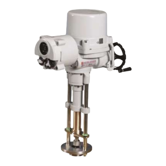
HL is a totally enclosed unit with a permanently lubricated gear train (Moly EP Grease). Once installed lubrication should not be required. However, periodic preventative maintenance will extend the operating life of the actuator. External Parts for Standard Models 3.2.1 HL 5,7,10,12,15,18,20,25KN External Parts HL SERIES ① Top Cover Body Auto & manual Lever ④ Cover bolt Conduit Entries (PF 3/4”)x2... -
Page 11: Internal Parts For Standard Models
Internal Parts for Standard Models ⑥ ⑦ ⑧ ① ② ③ ④ ⑤ ⑨ ⑩ Internal Parts HL SERIES Motor Potentiometer Terminal Open force switch (RED Color) Close force switch (BLUE Color) Close limit switch Open limit switch Capacitor PCU Board... -
Page 12: Installation Instruction
The actuator Union joint is removable for ease of machining. Caution ; Do not attempt to work on your HKC actuator without first shutting off incoming power. Do not attach ropes or hooks to the hand wheel for the purpose of lifting by hoist. -
Page 13: Actuator Mounting Details
4.2.1 Actuator Mounting Details If the linear actuator and the valve are supplied separately you will have to mount the linear actuator on the valve. Union nut Joint ring Guide rod nut(2ea) C 13... -
Page 14: Preparing Assembly
4.2.2 Preparing assembly Warning : A non-attached valve causes damage! If you operate the linear actuator without valve, the spindle nut may fall off due to the missing stop. ATTENTION • Always operate the linear actuator with a valve attached. Allow for about 200 mm space above the cover at the site of installation. -
Page 15: Limit Switch Setting
Limit Switch Setting Rotate the actuator hand wheel manually to closed position Using a hex wrench, loosen the set screw in the CLOSE limit switch cam Rotate the CLOSE cam towards CW limit switch lever until the switch ‘clicks’ (Fig 1) ... -
Page 16: Force Switch Setting
Once actuator is under overload, force switch is tripped and actuator stoped immediately. The force switches are set by manufacturer on the production site basically. Re-setting be necessary, please contact the HKC service or representative before setting. Caution ;... - Page 17 HL 10,12,15,18,20,25KN Open(up)100% →1kΩ Close(down) 0% →0Ω HL 5,7KN :Close(down) 0% →0Ω :Open(up)100% →1kΩ Tighten the point gear set screw with an hex wrench.(HL5,7KN) C 17...
- Page 18 Fix potentiometer by placing spring as per diagram A HL 10,12,15,18,20,25KN) Diagram B HL 5,7KN) C 18...
-
Page 19: Proportional Control Unit - Pcu (Option)
Proportional Control Unit – PCU (option) *Thanks for purchasing our Hl series electric actuator. Before installing or operating actuator, please read to this manual to know thoroughly how to install or operator. The contents in this manual is subject to change due to the quality improvement without individual notice. -
Page 20: Standard Specification
4.6.2 General performance PCU is the local actuator controller, using 12bit A/D converter and 8 bits Microprocessor, which operate actuator to open and close according to the input signal from main controller. After operating actuator, detect the current position of actuator and transmit feedback output signal about current position to the main controller. -
Page 21: Function Of Pcu And How To Set And To Use It
4.6.4 Function of PCU and how to set and to use it 1) Selecting of input signal User can select suitable input signal by adjusting DIP switches as follows. 2) Setting of fail position In order to prevent big trouble when input signal is failed, user can set the fail Position of actuator by setting of DIP switch as follows. - Page 22 Resolution Adjustmet This is set allowance between input signal and position of actuator and if turn this to clockwise, it is getting wider. Vice versa. Please be careful when turn this to counter-clockwise because if it us too Narrow, it could be the reason of “HUNTING”. HUNTING is that actuator dosen’t stop at a position and repeat to move to Manual operation by PCU card, In order to operate actuator by card, press ZERO and SPAN buttons together...
- Page 23 AUTO SETTING If mounting between actuator and application is correct, and input signal, Input power and wiring are correct, push AUTO SETTING button just 1 time Regardless of the position of Actuator. The Blue LED flickers with indicating LED as following. 1) Opening with Red LED in 5 sec ->...
- Page 24 Reversal acting switch(CH2) General clockwise-rotating direction of actuator is close but user wants reverse action, please do as follows. Switch “5” up = Signal : 20mA Full Closed Signal : 4mA Full Open Switch “5” down = Signal : 4mA Full Closed Signal : 20mA Full Open Put actuator 50% open(or close) position, and push AUTO SETTING button Supplying 4~20mA, check operation and rotating direction.
- Page 25 4.6.5. Check operation of PCU Actuator Full close Full open Input signal 4mA DC(1VDC, 2VDC)) 20mA DC(5VDC, 10VDC) Output signal 4mA DC 20mA DC Signal LED Green LED on Red LED on Auto setting Blue LED flicker Input signal failure Yellow LED flicker 4.6.6.
- Page 26 4.6.7. Layout of PCU CARD C 26...
- Page 27 Current Position Transmitter The potentiometer used for the actuator signal feedback The potentiometer reads the actuator’s current position and transfers a resistance value to a current position transmitter card. The CPT indicates the actuator position throughout the stroke by a 4~20mA output signal. 4.7.1 Standard Features Model Power...
-
Page 28: Operation Instruction
Operation Instruction Electrical Connections and Preliminary Test Warning ; When working in potentially explosive areas, observe the European Standards EN 60079-14 “Electrical Installations in Hazardous Areas” and EN 60079-17 “Inspection and Maintenance of Electrical Installations in Hazardous Areas”. Work on the electrical system or equipment must only be carried out by a skilled electrician himself or by specially instructed personnel under the control and supervision of such an electrician and in accordance with the applicable electrical engineering rules. -
Page 29: On/Off Type
Wiring Diagrams for Standard Models 5.2.1 On/off type HL 5KN,7KN,10KN,12KN,15KN HL 18KN,20KN,25KN C 29... -
Page 30: Pcu Type
5.2.2 PCU TYPE HL 5KN,7KN HL 10KN,12KN,15KN,18KN,20KN,25KN C 30... -
Page 31: Maintenance
Danger ; HAZARDOUS VOLTAGE. No electrical power should be connected until all wiring and limit switch adjustments have been completely. Once power is supplied to unit, exercise caution if cover is not installed. NOTE: More information, refers to the Appendix Ⅱ. Maintenance Maintenance Caution :... -
Page 32: Tools
Tools 1 Set Metric Allen Key (Hex Wrench) 1 Set Screw Drivers 1 Set Metric Spanner 1 Wrench 200mm 1 Wrench 300mm 1 Wire Stripper long Nose 1 Multi Meter (AC, DC, Resistance) ... -
Page 33: Dimensions For Actuator
Dimensions for actuator 7.1 5KN,7KN (on/off type) C 33... -
Page 34: 5Kn,7Kn(Control Type)
7.2 5KN,7KN (control type) C 34... - Page 35 7.3 10KN,12KN,15kn (on/off or control type) C 35...
-
Page 36: 10Kn,12Kn,15Kn(On/Off Type)
7.4 10KN,12KN,15kn (on/off or control & LCU) C 36... -
Page 37: 18Kn,20Kn,25Kn (Control Type)
7.5 18KN,20KN,25kn (on/off or control type) C 37... - Page 38 7.6 18KN,20KN,25kn (on/off or control & LCU) C 38...
-
Page 39: Trouble Shooting
Trouble Shooting The following instructions are offered for the most common difficulties encounter during installation and start-up. Actuator does not respond Verify the line voltage to the actuator Check that the voltage matches the rating on the actuator nameplate ... -
Page 40: Installation And Maintenance Tips
Installation and Maintenance Tips For any installation and maintenance work, the following should be observed : Caution : A regular inspection and maintenance performed by qualified and trained personnel When working in potentially explosive areas, observe the standard EN 60079-14 “Electrical Installations in Hazardous Areas”. - Page 41 Ⅰ Ⅰ HL series Coding System C 41...
-
Page 42: Hl-5Kn Abcdefg
HL – 5KN a b c d e f g Enclosure 1 : weather proof (IP 67) 2 : Submersible (IP 68, 10m / 72 hr) 3 : Ex type (EEx d IIB T4 IP 67) Input Voltage 1 : 110 VAC / 1 Ph 2 : 220 VAC / 1 Ph 3 : 220 VAC / 3 Ph 4 : 380 VAC / 3 Ph... -
Page 43: Hl-7Kn Abcdefg
HL – 7KN a b c d e f g Enclosure 1 : weather proof (IP 67) 2 : Submersible (IP 68, 10m / 72 hr) 3 : Ex type (EEx d IIB T4 IP 67) Input Voltage 1 : 110 VAC / 1 Ph 2 : 220 VAC / 1 Ph 3 : 220 VAC / 3 Ph 4 : 380 VAC / 3 Ph... -
Page 44: Hl-10Kn Abcdefg
HL – 10KN a b c d e f g Enclosure 1 : weather proof (IP 67) 2 : Submersible (IP 68, 10m / 72 hr) 3 : Ex type (EEx d IIB T4 IP 67) Input Voltage 1 : 110 VAC / 1 Ph 2 : 220 VAC / 1 Ph 3 : 220 VAC / 3 Ph 4 : 380 VAC / 3 Ph... -
Page 45: Hl-12Kn Abcdefg
HL – 12KN a b c d e f g Enclosure 1 : weather proof (IP 67) 2 : Submersible (IP 68, 10m / 72 hr) 3 : Ex type (EEx d IIB T4 IP 67) Input Voltage 1 : 110 VAC / 1 Ph 2 : 220 VAC / 1 Ph 3 : 220 VAC / 3 Ph 4 : 380 VAC / 3 Ph... - Page 46 HL – 15KN a b c d e f g Enclosure 1 : weather proof (IP 67) 2 : Submersible (IP 68, 10m / 72 hr) 3 : Ex type (EEx d IIB T4 IP 67) Input Voltage 1 : 110 VAC / 1 Ph 2 : 220 VAC / 1 Ph 3 : 220 VAC / 3 Ph 4 : 380 VAC / 3 Ph...
- Page 47 HL – 18KN a b c d e f g Enclosure 1 : weather proof (IP 67) 2 : Submersible (IP 68, 10m / 72 hr) 3 : Ex type (EEx d IIB T4 IP 67) Input Voltage 1 : 110 VAC / 1 Ph 2 : 220 VAC / 1 Ph 3 : 220 VAC / 3 Ph 4 : 380 VAC / 3 Ph...
- Page 48 HL – 20KN a b c d e f g Enclosure 1 : weather proof (IP 67) 2 : Submersible (IP 68, 10m / 72 hr) 3 : Ex type (EEx d IIB T4 IP 67) Input Voltage 1 : 110 VAC / 1 Ph 2 : 220 VAC / 1 Ph 3 : 220 VAC / 3 Ph 4 : 380 VAC / 3 Ph...
- Page 49 HL – 25KN a b c d e f g Enclosure 1 : weather proof (IP 67) 2 : Submersible (IP 68, 10m / 72 hr) 3 : Ex type (EEx d IIB T4 IP 67) Input Voltage 1 : 110 VAC / 1 Ph 2 : 220 VAC / 1 Ph 3 : 220 VAC / 3 Ph 4 : 380 VAC / 3 Ph...
- Page 50 If Explosion proof type actuator applied, HL – . . . 3 . 0 . . . 0 Force/Model a =3 Enclosure 1 : weather proof (IP 67) 2 : Submersible (IP 68, 10m / 72 hr) 3 : Ex type (EEx d IIB T4 IP 67) b =all Input Voltage...
Need help?
Do you have a question about the HL Series and is the answer not in the manual?
Questions and answers