Table of Contents
Advertisement
Installation, Operation and Maintenance Manual
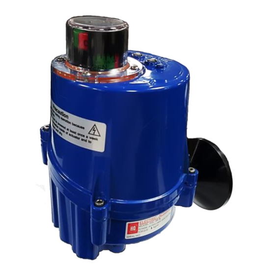
Small & Compact Design
High corrosion resistance
Beacon indicator with LED lamps
IP67 Weatherproof Aluminium housing
Multi-voltage Power Supply
Long life cycle
Unit 9, Evans Place, Durban Road, Bognor Regis, West Sussex, PO22 9RY
Tel: 01243 827469
HQ – 005. ELECTRIC ACTUATORS
QUARTER-TURN ELECTRIC ACTUATORS
Actuated Solutions Ltd
Fax: 01243 829418
Website: www.actuated-solutions.co.uk
HQ-005 Electric Actuators
Version – Ver. 1
Revision – Rev. 3
Document No. HKQI-611
Email: sales@actuated-solutions.co.uk
Advertisement
Table of Contents

Related Manuals for HKC HQ-005


Summary of Contents for HKC HQ-005
- Page 1 HQ – 005. ELECTRIC ACTUATORS QUARTER-TURN ELECTRIC ACTUATORS Installation, Operation and Maintenance Manual HQ-005 Electric Actuators Version – Ver. 1 Revision – Rev. 3 Document No. HKQI-611 Small & Compact Design High corrosion resistance Beacon indicator with LED lamps ...
-
Page 2: Table Of Contents
Storage ........................... 2 GENERAL INFORMATION AND FEATURES ..............3 General Information ......................3 3.1.1 Performance ............................3 3.1.2 Standard Technical Data ........................3 3.1.3 HQ-005 Optional Technical Data (Optional) ..................3 3.1.4 Duty Cycle ............................3 Torque Control 3.1.5 ........................... 4 3.1.6 Manual Override.......................... -
Page 3: Introduction
Installation, Operation and Maintenance Manual HQ-005 Electric Actuator INTRODUCTION Purpose The purpose of this manual is to introduce and explain the installation, operation and maintenance of HQ-005 electric actuators. A copy of all wiring diagrams can be found online at our website www.actuated-solutions.co.uk... -
Page 4: Product Identification
Installation, Operation and Maintenance Manual HQ-005 Electric Actuator PRODUCT IDENTIFICATION Product Identification The actuator name plate is located on the opposite side of the conduit entry. The name plate contains the following: 2.1.1 Marking A) General E L E C T R I C A C T U AT O R... -
Page 5: General Information And Features
Installation, Operation and Maintenance Manual HQ-005 Electric Actuator GENERAL INFORMATION AND FEATURES General Information HQ-005 electric actuators are designed for the operation of small size quarter turn valves; e.g. ball, butterfly and damper valves etc. with high reliability and efficiency. 3.1.1 Performance Max. -
Page 6: Torque Control
The lever in horizontal position = Dis-engaged 3.1.7 Lubrication HQ-005 electric actuator is a totally enclosed unit with permanent lubricated gear train (Moly EP Grease). Once installed, further lubrication should not be required. However, periodic preventative maintenance will extend the operating life of the actuator. -
Page 7: External Parts For Standard Models
Installation, Operation and Maintenance Manual HQ-005 Electric Actuator External Parts for Standard Models External Parts HQ-005 Top Cover Body Star drive (double square 14mm) Mounting base (F03, F04, F05,F07) Manual lever Name Plate Captive cover bolt Beacon Indicator Fully closed LED lamp (red color) -
Page 8: Installation
Installation, Operation and Maintenance Manual HQ-005 Electric Actuator INSTALLATION Pre-installation for using in General Service Verify the actuator’s nameplate to ensure correct model number, torque output, operating speed, voltage and enclosure type before installation or use. It is important to verify that the torque output of the actuator is appropriate for the torque requirements of the valve and that the duty cycle of the actuator is appropriate for the intended application. -
Page 9: Actuator Mounting Base Details
Installation, Operation and Maintenance Manual HQ-005 Electric Actuator 4.2.1 Actuator Mounting Base Details Direct Mounting Bracket Mounting (ISO Standard) Actuator: Fully Closed Valve: Fully Closed Note: Make sure both the actuator and valve are fully closed. Actuator Mounting Base: F03/F04/F05/F07 Star Adapter 14mm→9mm... -
Page 10: Limit Switch Setting
Installation, Operation and Maintenance Manual HQ-005 Electric Actuator Limit Switch Setting Manually rotate the hand wheel of the actuator to fully closed position Using a Allen key, loosen the set screw in the CLOSE limit switch cam Rotate the CLOSE cam towards CW limit switch lever until the switch ‘clicks’... -
Page 11: Maintenance
Installation, Operation and Maintenance Manual HQ-005 Electric Actuator MAINTENANCE Maintenance CAUTION: Turn off all power before attempting to perform maintenance on the actuator. POTENTIALLY HIGH PRESSURE VESSEL. Before removing disassembling your actuator, ensure that the valve or other actuated device is isolated and not under pressure. -
Page 12: Trouble Shooting
Installation, Operation and Maintenance Manual HQ-005 Electric Actuator TROUBLE SHOOTING The following instructions are listed in the order of the most common difficulties encountered during the installation and start-up. Symptom Probable Cause Corrective Action Refer to appropriate wiring diagram and check... - Page 13 Installation, Operation and Maintenance Manual HQ-005 Electric Actuator ! Optional Equipment(s) 1) Potentiometer Current Position Transmitter Check the resistance value Check potentiometer gear for jamming Check ZERO and SPAN calibration Check the board for any damage ...
-
Page 14: Dimensions
Installation, Operation and Maintenance Manual HQ-005 Electric Actuator DIMENSIONS Note: For more information regarding this product, please contact the manufacturer or your supplier for more details. Please refer to the website for the latest wiring diagrams. 12 | P a g e...
Need help?
Do you have a question about the HQ-005 and is the answer not in the manual?
Questions and answers