Table of Contents
Advertisement
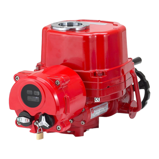
HQ(XC) Series Quarter-turn Electric Actuator
Installation Operation& Maintenance Manual
Quarter-turn Electric Actuator
HQ-Series (XC-Series)
Installation, Operation & Maintenance Manual
Address :
26, Emtibeui 28-ro, Siheung-si, Gyeonggi-do, (15119) Republic of Korea
Tel : +82-31-488-8266, Fax : +82-31-488-8269, Home page : www.hkcon.co.kr, email :
hkcon@hkcon.co.kr
Doc No. : HumC-HQ-21 Rev0
Page 1 / 21
Valve Automation Leader HKC
Advertisement
Table of Contents

Subscribe to Our Youtube Channel
Related Manuals for HKC HQ Series


Summary of Contents for HKC HQ Series
- Page 1 Installation, Operation & Maintenance Manual Address : 26, Emtibeui 28-ro, Siheung-si, Gyeonggi-do, (15119) Republic of Korea Tel : +82-31-488-8266, Fax : +82-31-488-8269, Home page : www.hkcon.co.kr, email : hkcon@hkcon.co.kr Doc No. : HumC-HQ-21 Rev0 Page 1 / 21 Valve Automation Leader HKC...
-
Page 2: Table Of Contents
7.4. Optional Equipment(s) ........................15 INSTALLATION AND MAINTENANCE TIPS ............15 APPENDIXⅠ. HQ(XE)-SERIES CODING SYSTEM ............17 APPENDIX II: WIRING DIAGRAM ..................18 APPENDIX III: GROUNDING ....................21 Doc No. : HumC-HQ-21 Rev1 Page 2 / 21 Valve Automation Leader HKC... -
Page 3: Introduction
HQ logo (trade mark), Model, Electrical power supply, Type, Rated current, Torque, Serial No., Operating time (seconds) and Option. ----- 20 Rev0] ② [Flameproof for CSA, IECEx/ATEX, KCs, and EAC ------ 20 Rev0] Doc No. : HumC-HQ-21 Rev1 Page 3 / 21 Valve Automation Leader HKC... -
Page 4: Initial Inspection
2.2.2 Check the product specification with product ordered. If a wrong product has been shipped, imme- diately report to our coordinator. 2.3. Storage Doc No. : HumC-HQ-21 Rev1 Page 4 / 21 Valve Automation Leader HKC... -
Page 5: General Information And Features
3.1. General HKC HQ(XC) series electric actuators are designed for the operation of industrial valves, e.g. butterfly valves and ball valves. Torque ranges of actuators are from 80Nm to 3,000Nm (690 In-Lbs to 25,900 In-Lbs), cur- rently ten models are available 3.1.1. - Page 6 HQ is a totally enclosed unit with a permanently lubricated gear train (Moly EP Grease). Once installed lubrication should not be required. However, periodic preventative maintenance will extend the operat- ing life of the actuator. Doc No. : HumC-HQ-21 Rev1 Page 6 / 21 Valve Automation Leader HKC...
-
Page 7: External Parts For Standard Models
It is important to verify that the torque output of the actuator is appropriate for the torque require- ments of the valve and that the duty cycle of the actuator is appropriate for the intended application. Doc No. : HumC-HQ-21 Rev1 Page 7 / 21 Valve Automation Leader HKC... -
Page 8: Actuator Mounting
To avoid backlash, flexibility in the mounting bracket or mounting should not be allowed. CAUTION: Do not attempt to work on your HKC actuator without first shutting off the incoming power. Do not attach ropes or hooks to the hand wheel for the purpose of lifting by hoist 4.2.4. -
Page 9: Limit Switch Setting
HAZARDOUS VOLTAGE. Make sure all incoming power is disconnected before setting the limit switch Upper Switch Lower Switch Figure 1: Close Cam Setting Figure 2: Open Cam Setting Doc No. : HumC-HQ-21 Rev1 Page 9 / 21 Valve Automation Leader HKC... -
Page 10: Torque Switch Setting
The torque switches are set by manufacturer on the production site. If re-setting is necessary, please contact the HKC service representative before setting the torque switch. Do not reset torque switch to a setting higher than the maximum setting stated by CAUTION: the manufacturer. -
Page 11: Current Position Transmitter - Cpt (Optional)
PCUC – AC (HKC model) PCUC - DC (HKC model) Notes : PCUC-AC or PCUC-DC PCU cards can be applicable to all of the CSA certified HQ series. DMC-100 or DHC-100 PCU cards from Peaktronics are possible to use only HQ-020 Model for CSA products. - Page 12 30A locked rotor for 3 seconds typical Environmental applicable condition Operating Temperature: -40 to 85 °C Storage Temperature: -50 to 105°C Relative Humidity: 0 to 90 % (at non-condensing) Doc No. : HumC-HQ-21 Rev1 Page 12 / 21 Valve Automation Leader HKC...
-
Page 13: Wiring
Make sure that the power supply voltage is in accordance with the data on the nameplate of the actuator. 5.1.3. Pass cables through the cable glands: NPT 3/4” for Ex “d” 5.1.4. Connect wires according to the enclosed wiring diagram. Doc No. : HumC-HQ-21 Rev1 Page 13 / 21 Valve Automation Leader HKC... -
Page 14: Maintenance
Verify the line voltage supplied to the actuator; check that the line voltage matches with the rating on the actuator’s nameplate 7.1.3. Check the internal wiring against the supplied wiring diagram of the actuator 7.1.4. Check the limit switch cams Doc No. : HumC-HQ-21 Rev1 Page 14 / 21 Valve Automation Leader HKC... -
Page 15: The Actuator Is Supplied With Power But Does Not Operate
8.2. Cable entries, cable glands, plugs, etc. have to be checked whether they are correctly tightened and sealed. Doc No. : HumC-HQ-21 Rev1 Page 15 / 21 Valve Automation Leader HKC... - Page 16 8.9. Any kind of surface coating for the gap surface is not permitted. 8.10. When replacing parts, seals, etc., only original spare ones must be used. Doc No. : HumC-HQ-21 Rev1 Page 16 / 21 Valve Automation Leader HKC...
-
Page 17: Appendixⅰ. Hq(Xe)-Series Coding System
*1: This option shall not be applied to CSA items. More details should be advised to the manufacturer. --- 16 Rev0] *2: This option shall not be applied to IECEx/ATEX items. --- 17 Rev.0] Doc No. : HumC-HQ-21 Rev1 Page 17 / 21 Valve Automation Leader HKC... -
Page 18: Appendix Ii: Wiring Diagram
Appendix II: Wiring Diagram HQ-008/010 Standard 1Ph. HQ-008/010 Standard DC DANGER: HAZARDOUS VOLTAGE. No electrical power should be connected until all wiring and limit switch adjustments have been completed. Doc No. : HumC-HQ-21 Rev1 Page 18 / 21 Valve Automation Leader HKC... - Page 19 HQ-015 ~ 300 Standard 1Ph. PCU --- 17 Rev1] DANGER: HAZARDOUS VOLTAGE. No electrical power should be connected until all wiring and limit switch adjustments have been completed. Doc No. : HumC-HQ-21 Rev1 Page 19 / 21 Valve Automation Leader HKC...
- Page 20 HQ-015 ~ 030 Standard DC HQ-015 ~ 030 Standard DC PCU --- 17 Rev1] NOTE: Each actuator is packed with individual box, and you can get the wiring diagram inside. Doc No. : HumC-HQ-21 Rev1 Page 20 / 21 Valve Automation Leader HKC...
-
Page 21: Appendix Iii: Grounding
26, Emtibeui 28-ro, Siheung-si, Gyeonggi-do, 15119, Republic of Korea Head Office & Plant: Tel) +82-31-488-8266, Fax) +82-31-488-8269 Fax) Overseas sales office: +82-31-488-9622, Domestic sales office: +82-31-319-8267 Website www.hkcon.co.kr Doc No. : HumC-HQ-21 Rev1 Page 21 / 21 Valve Automation Leader HKC...
Need help?
Do you have a question about the HQ Series and is the answer not in the manual?
Questions and answers