Sign In
Upload
Download
Table of Contents
Contents
Add to my manuals
Delete from my manuals
Share
URL of this page:
HTML Link:
Bookmark this page
Add
Manual will be automatically added to "My Manuals"
Print this page
×
Bookmark added
×
Added to my manuals
Manuals
Brands
HKC Manuals
Controller
HM04
Installation and maintenance manual
HKC HM04 Installation And Maintenance Manual
Hide thumbs
1
Table Of Contents
2
3
4
5
6
7
8
9
10
11
12
13
14
15
16
17
18
19
20
21
22
23
24
25
26
27
28
29
page
of
29
Go
/
29
Contents
Table of Contents
Troubleshooting
Bookmarks
Table of Contents
Table of Contents
1 Introduction
Purpose
Manual Guidelines Contents
External Parts for Standard Models
Safety Notices
2 Product Identification
Marking
Initial Inspection
Storage
3 General Information and Features
General
Performance Data
AC 3Phase Model & Torque(Nm)
AC 1Phase Model & Torque(Nm)
Solid State Design Model & Torque(Nm)
Mechanical Data
HM Standard Technical Data (Standard)
HM Option Technical Data (Optional)
Duty Cycle
Hand Wheel and Declutching
Lubrication
Internal Parts for Standard Models
4 Installation and Operation Instruction
Pre-Installation for Use in General Service
Actuator Mounting
Actuator Mounting Details (ISO5211&5210)
Mounting Base
Disassembly and Assembly of Mounting Base
Disassembly and Assembly the Drive Bush in Thrust Base
Electrical Connections and Preliminary Test
5 Maintenance
Tools
6 Trouble Shooting
7 Installation and Maintenance Tips
8 Wiring Diagram
HM-Standard 3Ph, CPT,PCU
9 Dimension
10 Grounding
APPENDIX I : HM-Series Coding System
Advertisement
Quick Links
1
Manual Guidelines Contents
2
Ac 3Phase Model & Torque(Nm)
3
Installation and Operation Instruction
4
Tools
5
Trouble Shooting
6
Wiring Diagram
7
Appendix I : Hm-Series Coding System
Download this manual
HKC CO.,LTD.
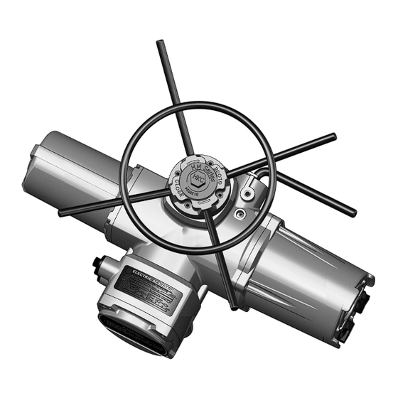
HM – Series. ELECTRIC ACTUATORS
INTELLIGENT MULTI-TURN ELECTRIC ACTUATORS
VALVE AUTOMATON
Installation and Maintenance Manual
HKC
HM-SERIES / ACTUATORS
Version- V1
Document No. HQOI-08-EV1
DATE : 2011.12.22
H K C
WWW.HKCON.CO.KR
Table of
Contents
Previous
Page
Next
Page
1
2
3
4
5
Advertisement
Table of Contents
Need help?
Do you have a question about the HM04 and is the answer not in the manual?
Ask a question
Questions and answers
Related Manuals for HKC HM04
Controller HKC HQ-005 Installation, Operation And Maintenance Manual
Quarter-turn electric actuators (14 pages)
Controller HKC HQ Series Installation, Operation & Maintenance Manual
Quarter-turn electric actuator (26 pages)
Controller HKC HM Series Installation And Maintenance Manual
(29 pages)
Controller HKC HP Series Installation, Operation & Maintenance Manual
Pneumatic actuator (18 pages)
Controller HKC HQ-005 RBP Installation, Operation & Maintenance Manual
Quarter-turn electric actuator (8 pages)
Controller HKC HQ-004 Installation, Operation & Maintenance Manual
Quarter-turn electric actuator (9 pages)
Controller HKC HQ Series Installation, Operation & Maintenance Manual
Quarter-turn electric actuator (21 pages)
Controller HKC HQ-006 Installation, Operation & Maintenance Manual
Quarter-turn electric actuator (22 pages)
Controller HKC HL Series Installation & Operation Manual
Linear electric actuator (50 pages)
Controller HKC HL Series Installation, Operation & Maintenance Manual
Electric linear actuator (26 pages)
Controller HKC ET Series Installation, Operation & Maintenance Manual
Heavy-duty pneumatic actuators (18 pages)
Controller HKC ET Series Installation, Operation & Maintenance Manual
Heavy-duty pneumatic actuators (17 pages)
This manual is also suitable for:
Hm11
Hm20
Hm series
Hm08
Hm40
Hm60
...
Show all
Hm100
Hm150
Hm200
Hm300
Hm04 s3
Hm11 s3
Hm08 s3
Table of Contents
Save PDF
Print
Rename the bookmark
Delete bookmark?
Delete from my manuals?
Login
Sign In
OR
Sign in with Facebook
Sign in with Google
Upload manual
Upload from disk
Upload from URL


Need help?
Do you have a question about the HM04 and is the answer not in the manual?
Questions and answers