Table of Contents
Advertisement
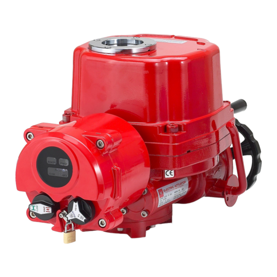
HQ Series Quarter-turn Electric Actuator
Installation Operation& Maintenance Manual
HQ Series Quarter-turn Electric Actuator
Installation, Operation & Maintenance Manual
Address : 26, Emtibeui 28-ro, Siheung-si, Gyeonggi-do, (15119) Republic of Korea
Tel : +82-31-488-8266, Fax : +82-31-488-8269, Home page : www.hkcon.co.kr, email :
hkcon@hkcon.co.kr
Doc No. : HumG-HQ-21 Rev2
Page 1 / 26
Valve Automation Leader, HKC
Advertisement
Table of Contents

Related Manuals for HKC HQ Series


Summary of Contents for HKC HQ Series
- Page 1 HQ Series Quarter-turn Electric Actuator Installation Operation& Maintenance Manual HQ Series Quarter-turn Electric Actuator Installation, Operation & Maintenance Manual Address : 26, Emtibeui 28-ro, Siheung-si, Gyeonggi-do, (15119) Republic of Korea Tel : +82-31-488-8266, Fax : +82-31-488-8269, Home page : www.hkcon.co.kr, email : hkcon@hkcon.co.kr...
-
Page 2: Table Of Contents
Actuator runs erratically ........................... 21 8.4. Optional Equipment(s) ............................21 Installation and Maintenance Tips ....................... 21 Appendix I: HQ series Coding System ......................22 Appendix II: Wiring Diagram......................... 23 Appendix III: Grounding ..........................26 Doc No. : HumG-HQ-21 Rev2 Page 2 / 26... -
Page 3: Introduction
HQ Series Quarter-turn Electric Actuator Installation Operation& Maintenance Manual 1. Introduction 1.1. Purpose The purpose of this manual is to introduce and explain the installation, operation and maintenance of HQ-series electric actuators. This IOM Manual is distributed as a hard copy when delivered the ordered products to customer. -
Page 4: Initial Inspection
HQ Series Quarter-turn Electric Actuator Installation Operation& Maintenance Manual 2.1.2. Applied Standard ① [IEC60079-0:2011(Ed.6 +IS01, EN60079-0:2012 +A11 ② IEC60079-1:2014-06 (Ed.7), EN60079-1:2014 ③ IEC60079-31:2013(Ed.2), EN60079-31:2014 ----- 17 Rev0] 2.1.3. Certification ① [IECEx: for HQ-008 ~ HQ-300 with LCU, IECEx DEK 16.0042X Ex db IIB T4 Gb, Ta -20℃... -
Page 5: General Information And Features
Lbs). Currently 19 models are available. [In case of explosion proof or dust ignition proof type, the rated current may be different due to the difference in the approved data, so please contact HKC. –--21 r0] 3.1.1. Standard technical data Max. - Page 6 HQ Series Quarter-turn Electric Actuator Installation Operation& Maintenance Manual 3.1.4. Optional technical data Flameproof enclosure IECEx, ATEX, CSA, KCs, [EAC ----- 20 Rev0] EXTB Dust Ignition proof enclosure IECEx, ATEX, KCs, [EAC ----- 20 Rev0] Watertight enclosure (IP68 10m / 72hr) Potentiometer unit (0~1KΩ)
-
Page 7: External Parts For Standard Models
HQ Series Quarter-turn Electric Actuator Installation Operation& Maintenance Manual 3.2. External Parts for Standard Models 3.2.1. HQ-008 ~ HQ-120 3.2.2. HQ-200 ~ HQ-300 (Actuator + Gear Box) 3.3. Internal parts for standard model 3.3.1. HQ-008 ~ HQ-080 Note: HQ-008~HQ-010 does not contain torque switch assembly. -
Page 8: Actuator Mounting
To avoid backlash, flexibility in the mounting bracket or mounting should not be allowed. CAUTION: Do not attempt to work on your HKC actuator without first shutting off the incoming power. Do not attach ropes or hooks to the hand wheel for the purpose of lifting by hoist 4.2.4. -
Page 9: Limit Switch Setting
4.4.2. The torque switches are set by manufacturer on the production site. If re-setting is necessary, please contact the HKC service representative before setting the torque switch. CAUTION: Do not reset torque switch to a setting higher than the maximum setting stated by the manufacturer. -
Page 10: Setting Potentiometer (Replacement And Setting)
HQ Series Quarter-turn Electric Actuator Installation Operation& Maintenance Manual 4.6.1. Loosen both (open and close) travel stopper bolt nuts by 3-4 threads. 4.6.2. By turning the hand wheel, manually operate the actuator so that it is in close position until it makes a contact with the closed limit switch. -
Page 11: Proportional Control Unit
HQ Series Quarter-turn Electric Actuator Installation Operation& Maintenance Manual 4.8.2. Calibration of Zero and Span – CPT The settings of Zero and Span have been calibrated at the factory. However, if re- calibration is required, proceed as follows: ① Apply power (or use the manual override) to drive the actuator to its fully closed position (clockwise rotation). - Page 12 HQ Series Quarter-turn Electric Actuator Installation Operation& Maintenance Manual 4.9.3. Standard Specification Table 1: Standard specification of the Proportional Control Unit Model PCU EB-V1.5D (for AC) PCU DC-V2.1C (for DC) Indicated on the board PCU_EB_V1.5D-CONTROL HKC-PCU_DC-MAIN-V2.1C Applied Electronic Breaking system Special function (EB) for high resolution control.
- Page 13 HQ Series Quarter-turn Electric Actuator Installation Operation& Maintenance Manual Depending on the system environment, the user can select the required output feedback signal by setting the DIP switch as above table. Notes : DIP switch is commonly set with 4~20mA dc before shipping.
- Page 14 HQ Series Quarter-turn Electric Actuator Installation Operation& Maintenance Manual ① Check connection status of the input power and input/output signal after actuator and valve are correctly assembled. ② If there is no problem with the wiring, push the auto setting button once (ASCAN).
- Page 15 HQ Series Quarter-turn Electric Actuator Installation Operation& Maintenance Manual 4.9.11. Random command signal setting Dip Switch PCU model Power source PCU-EB-V1.5D for AC PCU-DC-V2.1C for DC ① This function is intended to change the Zero (fully close) and Span (Fully open) signal.
- Page 16 HQ Series Quarter-turn Electric Actuator Installation Operation& Maintenance Manual Wait until only the Green LED flickers after both Red and Green LED flicker for about 1.5 second. Turn down No. 4 switch of the dip switch. ※ If No. 4 switch of the dip switch is turned down during the setting process, the setting will be cancelled.
-
Page 17: Ac/Dc Multi-Board
HQ Series Quarter-turn Electric Actuator Installation Operation& Maintenance Manual Error type LED display (Malfunction) Blue Green Yellow Input signal initialization error Reverse turn the motor Auto setting initialization error EEPROM error Input signal error Open position error Close position error... -
Page 18: Modbus Controller
HQ Series Quarter-turn Electric Actuator Installation Operation& Maintenance Manual ① Multiple remote control of valve actuator with AC power 5.1.9. Specification Item Description Unit 87V ~ 270V ac ±10% , 50/60Hz ±2% 4VA max. Input power V, A Input power must match motor ratings... -
Page 19: Wiring
HQ Series Quarter-turn Electric Actuator Installation Operation& Maintenance Manual certain values defined as inputs while other values are outputs, such as current temperature or valve position. 5.2.5. Specification ① Communication Protocol : Modbus-RTU according to IEC 61158 and IEC 61784 ②... -
Page 20: Maintenance
HQ Series Quarter-turn Electric Actuator Installation Operation& Maintenance Manual 7. Maintenance 7.1. Maintenance WARNING: Turn off all power before attempting to perform maintenance on the actuator. POTENTIALLY HIGH PRESSURE VESSEL. Before removing or disassembling your actuator, ensure that the ... -
Page 21: Actuator Runs Erratically
HQ Series Quarter-turn Electric Actuator Installation Operation& Maintenance Manual 8.2.9. Verify that coupler/bracket is correctly installed and is not causing any binding 8.3. Actuator runs erratically 8.3.1. Check the ambient temperature 8.3.2. Verify that the duty cycle has not been exceeded 8.3.3. -
Page 22: Appendix I: Hq Series Coding System
HQ Series Quarter-turn Electric Actuator Installation Operation& Maintenance Manual Appendix I: HQ series Coding System [Note: Coding system was consolidated from each model’s ------ 15 Rev0] HQ – A a b c d e f g Example : Model Name... -
Page 23: Appendix Ii: Wiring Diagram
HQ Series Quarter-turn Electric Actuator Installation Operation& Maintenance Manual Appendix II: Wiring Diagram HQ-008/010 Standard 1Ph. HQ-008/010 Standard DC DANGER: HAZARDOUS VOLTAGE. No electrical power should be connected until all wiring and limit switch adjustments have been completed. Doc No. : HumG-HQ-21 Rev2... - Page 24 HQ Series Quarter-turn Electric Actuator Installation Operation& Maintenance Manual HQ-015 ~ 300 Standard 1Ph. HQ-015 ~ 300 Standard 1Ph. PCU --- 17 Rev1] DANGER: HAZARDOUS VOLTAGE. No electrical power should be connected until all wiring and limit switch adjustments have been completed.
- Page 25 HQ Series Quarter-turn Electric Actuator Installation Operation& Maintenance Manual HQ-015 ~ 030 Standard DC HQ-015 ~ 030 Standard DC PCU --- 17 Rev1] DANGER: HAZARDOUS VOLTAGE. No electrical power should be connected until all wiring and limit switch adjustments have been completed.
-
Page 26: Appendix Iii: Grounding
HQ Series Quarter-turn Electric Actuator Installation Operation& Maintenance Manual Appendix III: Grounding [HQ-008/010 HQ-015 and bigger size ------ 19 Rev0] HKC Co., Ltd. 26, Emtibeui 28-ro, Siheung-si, Gyeonggi-do, 15119, Republic of Korea Head Office & Plant: Tel) +82-31-488-8266, Fax) +82-31-488-8269...
Need help?
Do you have a question about the HQ Series and is the answer not in the manual?
Questions and answers