Advertisement
Quick Links
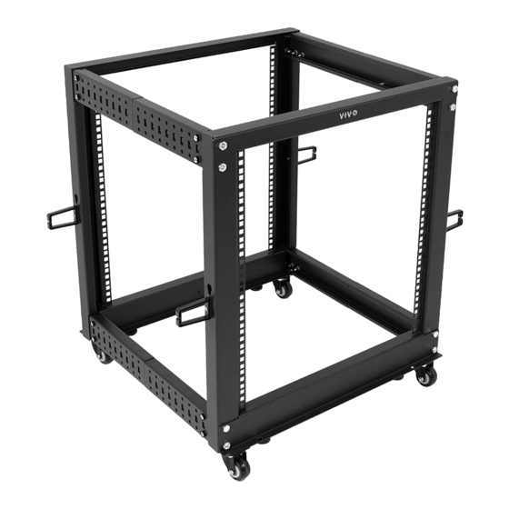
Black 12U Server Rack
Instruction Manual
SKU: CART-SR12U
Scan the QR code with your mobile device or follow the link
for helpful videos and specifications related to this product.
https://vivo-us.com/products/cart-sr12u
GET IN TOUCH | Monday-Friday from 7:00am-7:00pm CST
help@vivo-us.com
www.vivo-us.com
Chat live with an agent!
309-278-5303
Advertisement

Related Manuals for Vivo CART-SR12U


Summary of Contents for Vivo CART-SR12U
- Page 1 Black 12U Server Rack Instruction Manual SKU: CART-SR12U Scan the QR code with your mobile device or follow the link for helpful videos and specifications related to this product. https://vivo-us.com/products/cart-sr12u GET IN TOUCH | Monday-Friday from 7:00am-7:00pm CST help@vivo-us.com www.vivo-us.com...
-
Page 2: Package Contents
WARNING! If you do not understand these directions, or if you have any doubts about the safety of the installation, please call a qualified technician. Check carefully to make sure there are no missing or defective parts. Improper installation may cause damage or serious injury. -
Page 3: Assembly Steps
ASSEMBLY STEPS STEP 1 Slide Adjustment Supports (D) onto Adjustment Crossbars (E). Determine the maxium required mounting depth for your equipment and use the associated Setting Numbers from the chart. Align the Setting Numbers on the Adjustment Crossbar (E) with the inner rectangular cutouts on Adjustment Supports (D) shown below (labeled “Read from here”). - Page 4 STEP 2 Assemble Bottom Supports (A) and Adjustment Crossbars (E) with Adjustment Supports (D) to Vertical Supports Left (C) using M8x20mm Screws (S-A) and Wrench (T-A). Connect the two assemblies with Vertical Supports Right (B) as shown below using M8x20mm Screws (S-A) and Wrench (T-A).
- Page 5 STEP 3 Secure Adjustment Crossbars (E) with Adjustment Supports (D) and Upper Supports (G) to Vertical Supports Right (B) and Veritcal Supports Left (C) using M8x20mm Screws (S-A) and Wrench (T-A).
- Page 6 STEP 4 Install Feet (H) to Bottom Supports (A). Assemble Casters (F) to the cart assembly using M6x12mm Screws (S-B) with M6 Nuts (S-D) and Wrench (T-A).
- Page 7 STEP 5 Secure Hooks (I) to Vertical Supports Right (B) and Vertical Supports Left (C) using M4x16mm Screws (S-E).
- Page 8 AVG. RESPONSE TIME (within office hrs) - 23% within < 15m - 38% within < 30m - 61% within < 1hr - 83% within < 2hr - 92% within < 3hr FOR MORE VIVO PRODUCTS, CHECK OUT OUR WEBSITE AT: www.vivo-us.com...
Need help?
Do you have a question about the CART-SR12U and is the answer not in the manual?
Questions and answers