
Related Manuals for WIKA IPT-1 series


Summary of Contents for WIKA IPT-1 series
- Page 1 Operating Instructions Process pressure transmitter IPT-1* 4 … 20 mA/HART metallic sensor Version 3.0 Process pressure transmitter IPT-1*...
-
Page 2: Table Of Contents
Set up with PACTware and other adjustment programs Connect the PC ......................37 Parameter adjustment with PACTware ................37 Parameter adjustment with AMS™ and PDM ..............38 Saving the parameter adjustment data ................38 8 Maintenance and fault rectification WIKA Operating Instructions - Process pressure transmitter IPT-1*... - Page 3 Supplementary documents appropriate to the ordered version come with the delivery. You can find them listed in chapter "Product descrip- tion". Instructions manuals for accessories and replacement parts Tip: To ensure reliable setup and operation of your IPT-1*, we offer acces- sories and replacement parts. The corresponding documentations are: • Operating instructions manual "External display and adjustment unit" Editing status: 2015-04-29 WIKA Operating Instructions - Process pressure transmitter IPT-1*...
-
Page 4: About This Document
The dot set in front indicates a list with no implied sequence. → Action This arrow indicates a single action. Sequence of actions Numbers set in front indicate successive steps in a procedure. Battery disposal This symbol indicates special information about the disposal of bat- teries and accumulators. WIKA Operating Instructions - Process pressure transmitter IPT-1*... -
Page 5: For Your Safety
Arbi- trary conversions or modifications are explicitly forbidden. The safety approval markings and safety tips on the device must also be observed. WIKA Operating Instructions - Process pressure transmitter IPT-1*... -
Page 6: Safety Label On The Instrument
2.10 Safety instructions for oxygen applications For instruments in oxygen applications the special instructions in chapters "Storage and transport", "Mounting" as well as "Technical data" under "Process conditions"must be noted. Furthermore the valid national regulations, implementation instructions and memorandums of the professional assocations must be noted. WIKA Operating Instructions - Process pressure transmitter IPT-1*... -
Page 7: Product Description
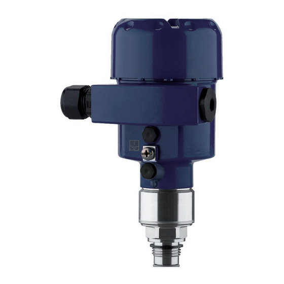
Housing cover with integrated display and adjustment module (optional) Housing with electronics Process fitting with measuring cell Type label The type label contains the most important data for identification and use of the instrument: • Instrument type • Article and serial number device WIKA Operating Instructions - Process pressure transmitter IPT-1*... -
Page 8: Principle Of Operation
The instrument can be adjusted with the following adjustment media: • With the display and adjustment module • the suitable WIKA DTM in conjunction with an adjustment software according to the FDT/DTM standard, e.g. PACTware and PC • With manufacturer-specific adjustment programs AMS™ or PDM •... - Page 9 • Not exposed to corrosive media • Protected against solar radiation • Avoiding mechanical shock and vibration • Storage and transport temperature see chapter "Supplement - Storage and transport temperature Technical data - Ambient conditions" • Relative humidity 20 … 85 % WIKA Operating Instructions - Process pressure transmitter IPT-1*...
-
Page 10: Mounting
Fig. 2: Measures against moisture ingress Ventilation and pressure The ventilation of the electronics housing as well as the atmospheric compensation pressure compensation for the measuring cell are realised via a filter element in the area of the cable gland. WIKA Operating Instructions - Process pressure transmitter IPT-1*... - Page 11 Make sure that the upper temperature limits for the environment of electronics housing and connection cable specified in chapter "Tech- nical data" are not exceeded. Oxygen applications Instruments in the version "Oil and grease free for oxygen" should be unpacked just before mounting. After the protective cover of the process fitting has been removed, the label "O " on the process fitting is visible. Danger: Avoid oil, grease or contamination. Explosion danger! WIKA Operating Instructions - Process pressure transmitter IPT-1*...
-
Page 12: Mounting Instructions
Screw IPT-1* into the welded socket. Tighten the hexagon on the process fitting with a suitable wrench. Wrench size, see chapter "Dimensional drawings". Warning: The housing must not be used to screw the instrument in! Applying tightening force can damage internal parts of the housing. Sealing/Installing hy- Use the seal suitable for the respective process fitting. You can find gienic fittings the components in the supplementary instructions manual "Welded socket and seals". Probable position correction see chapter "Setup steps". WIKA Operating Instructions - Process pressure transmitter IPT-1*... -
Page 13: Connecting To Power Supply
(e. g. 1 nF, 1500 V). The low-frequency potential equalisation currents are thus suppressed, but the protective effect against high frequency interfer- ence signals remains. Warning: Considerable potential differences exist inside galvanic plants as well as vessels with cathodic corrosion protection. Very large equalisa- tion currents can flow through the cable screen when the screen WIKA Operating Instructions - Process pressure transmitter IPT-1*... -
Page 14: Connection Procedure
5. Insert the cable into the sensor through the cable entry 6. Lift the opening levers of the terminals with a screwdriver (see following illustration) 7. Insert the wire ends into the open terminals according to the wir- ing plan WIKA Operating Instructions - Process pressure transmitter IPT-1*... -
Page 15: Wiring Plan, Single Chamber Housing
12. Screw the housing lid back on The electrical connection is finished. Wiring plan, single chamber housing The following illustrations apply to the non-Ex as well as to the Ex-ia version. WIKA Operating Instructions - Process pressure transmitter IPT-1*... - Page 16 Ground terminal for connection of the cable screen Spring-loaded terminals for voltage supply Wiring plan Display I 2 C Fig. 7: Wiring plan, single chamber housing Voltage supply, signal output WIKA Operating Instructions - Process pressure transmitter IPT-1*...
-
Page 17: Wiring Plan, Double Chamber Housing
Terminals for the external display and adjustment unit Terminal compartment I 2 C Fig. 9: Terminal compartment, double chamber housing Spring-loaded terminals for voltage supply Plug connector for service interface Ground terminal for connection of the cable screen WIKA Operating Instructions - Process pressure transmitter IPT-1*... - Page 18 Pin 1 Pin 2 Pin 3 Pin 4 Contact pin Colour connection ca- Terminal, electronics ble in the sensor module Pin 1 Brown Pin 2 White Pin 3 Blue Pin 4 Black WIKA Operating Instructions - Process pressure transmitter IPT-1*...
-
Page 19: Wiring Plan, Double Chamber Housing Ex D
Terminals for the external display and adjustment unit Terminal compartment Fig. 13: Connection compartment, Ex-d-ia double chamber housing Spring-loaded terminals for power supply and cable screen Ground terminal for connection of the cable screen WIKA Operating Instructions - Process pressure transmitter IPT-1*... - Page 20 Pin 1 Pin 2 Pin 3 Pin 4 Contact pin Colour connection ca- Terminal, electronics ble in the sensor module Pin 1 Brown Pin 2 White Pin 3 Blue Pin 4 Black WIKA Operating Instructions - Process pressure transmitter IPT-1*...
-
Page 21: Wiring Plan, External Housing With Version Ip 68 (25 Bar)
Spring-loaded terminals for voltage supply Ground terminal for connection of the cable screen Cable gland to the process component For external display and adjustment unit, Slave sensor Plug connector for service interface WIKA Operating Instructions - Process pressure transmitter IPT-1*... -
Page 22: Switch-On Phase
After connecting IPT-1* to power supply or after a voltage recurrence, the instrument carries out a self-check for approx. 30 seconds: • Internal check of the electronics • Indication of the instrument type, the firmware as well as the sen- sor TAGs (sensor designation) • Output signal jumps briefly (approx. 10 seconds) to the set fault current WIKA Operating Instructions - Process pressure transmitter IPT-1*... - Page 23 5 Connecting to power supply Then the corresponding current is outputted to the cable (the value corresponds to the actual level as well as the settings already carried out, e.g. factory setting). WIKA Operating Instructions - Process pressure transmitter IPT-1*...
-
Page 24: Set Up With The Display And Adjustment Module
4. Screw housing cover with inspection window tightly back on Disassembly is carried out in reverse order. The display and adjustment module is powered by the sensor, an ad- ditional connection is not necessary. WIKA Operating Instructions - Process pressure transmitter IPT-1*... -
Page 25: Adjustment System
Adjustment system Fig. 21: Display and adjustment elements LC display Indication of the menu item number Adjustment keys WIKA Operating Instructions - Process pressure transmitter IPT-1*... -
Page 26: Setup Steps
Parameter adjustment Set up IPT-1* in the following sequence: "Level measurement" 1. Selecting adjustment unit/density unit 2. Carry out a position correction 3. Carry out min. adjustment 4. Carry out max. adjustment WIKA Operating Instructions - Process pressure transmitter IPT-1*... - Page 27 When switching over to adjustment in a height unit (in the example from bar to m), the density also has to be entered. Proceed as follows: Selection options: mbar, bar, psi, Pa, kPa, MPa, inHg, mmHg, inH WIKA Operating Instructions - Process pressure transmitter IPT-1*...
- Page 28 Position correction Accept current measured value? ▶ Accept Edit 3. Confirm with [OK] and move to min.(zero) adjustment with [->]. Carry out min. adjustment Proceed as follows: 1. Edit the % value in the menu item "Min. adjustment" with [OK]. Selection options: °C, °F. WIKA Operating Instructions - Process pressure transmitter IPT-1*...
- Page 29 Parameter adjustment Set up IPT-1* in the following sequence: "Process pressure meas- 1. Select application "Process pressure measurement" urement" 2. Select the unit of measurement 3. Carry out a position correction 4. Carrying out zero adjustment WIKA Operating Instructions - Process pressure transmitter IPT-1*...
- Page 30 To select the adjustment unit (in the example switching over from bar to mbar), proceed as follows: 1. Push the [OK] button in the measured value display, the menu overview is displayed. Selection options: mbar, bar, psi, Pa, kPa, MPa, inHg, mmHg, inH WIKA Operating Instructions - Process pressure transmitter IPT-1*...
- Page 31 Position correction Accept current measured value? ▶ Accept Edit 3. Confirm with [OK] and move to min.(zero) adjustment with [->]. Carrying out zero adjust- Proceed as follows: ment 1. Edit the mbar value in the menu item "zero" with [OK]. Selection options: °C, °F. WIKA Operating Instructions - Process pressure transmitter IPT-1*...
- Page 32 A description of the function is available in the operating instructions manual "Display and adjustment module". The following data are read out or written with this function: • Measured value presentation • Adjustment • Damping WIKA Operating Instructions - Process pressure transmitter IPT-1*...
- Page 33 Span/Max. adjustment Measuring range end Density 1 kg/l Density unit kg/l Damping Linearization Linear Sensor-TAG Sensor Display Displayed value 1 Displayed value 2 With instruments with signal output 4 … 20 mA/HART WIKA Operating Instructions - Process pressure transmitter IPT-1*...
-
Page 34: Menu Schematic
Menu schematic Information: Depending on the version and application, the highlighted menu windows may not always be available. With instruments with signal output 4 … 20 mA/HART WIKA Operating Instructions - Process pressure transmitter IPT-1*... - Page 35 ▼ Switched off Diagnostics Basic adjustment Display ▶ Diagnostics Service Info Peak value indicator Sensor status Trend curve p-min.: -5.8 mbar p-max.: 167.5 mbar Start trend curve? T-min.: -12.5 °C T-max.: +85.5 °C WIKA Operating Instructions - Process pressure transmitter IPT-1*...
-
Page 36: Saving The Parameter Adjustment Data
If it is necessary to exchange the sensor, the display and adjustment module is inserted into the replacement instrument and the data are written into the sensor under the menu item "Copy sensor data". WIKA Operating Instructions - Process pressure transmitter IPT-1*... -
Page 37: Set Up With Pactware And Other Adjustment Programs
Keep in mind that for the setup of model IPT-1*, the current version of the DTM-Collection must be used. The latest DTM Collection and PACTware version can be downloaded free of charge via the Internet. WIKA Operating Instructions - Process pressure transmitter IPT-1*... -
Page 38: Parameter Adjustment With Ams™ And Pdm
It is recommended to document or save the parameter adjustment data. That way they are available for multiple use or service purposes. The WIKA DTM Collection and PACTware in the licensed, profession- al version provide suitable tools for systematic project documentation and storage. -
Page 39: Maintenance And Fault Rectification
4 … 20 mA Level fluctuations – Set the integration time via the signal not display and adjustment module or stable PACTware No atmospheric pres- – Check the pressure compensation sure compensation in the housing and clean the filter element, if necessary WIKA Operating Instructions - Process pressure transmitter IPT-1*... -
Page 40: Instrument Repair
Clean the instrument and pack it damage-proof • Attach the completed form and possibly also a safety data sheet to the instrument Fault message can also appear if the pressure is higher than the nominal range. WIKA Operating Instructions - Process pressure transmitter IPT-1*... -
Page 41: Dismount
We use recyclable materials and have designed the parts to be easily separable. Materials: see chapter "Technical data" If you have no way to dispose of the old instrument properly, please contact us concerning return and disposal. WIKA Operating Instructions - Process pressure transmitter IPT-1*... -
Page 42: Supplement
Synthetic oil for measuring ranges up to 16 bar, FDA listed for the food processing industry. For measuring ranges up to 25 bar dry measuring cell. Halocarbon oil: Generally in oxygen applications, not with vacuum measuring ranges, not with absolute meas- uring ranges < 1 bar Depending on the respective instrument and the process fitting, the temperature can deviate from the real process temperature. WIKA Operating Instructions - Process pressure transmitter IPT-1*... - Page 43 10 : 1 (no limitation) Nominal measuring ranges and overload capability in bar/kPa The specifications are only an overview and refer to the measuring cell. Limitations due to the ma- terial and version of the process fitting are possible. The specifications on the nameplate apply. Nominal range Overload capacity, max. Overload capacity, min. pres- pressure sure Gauge pressure 0 … +0.4 bar/0 … +40 kPa +2 bar/+200 kPa -1 bar/-100 kPa WIKA Operating Instructions - Process pressure transmitter IPT-1*...
- Page 44 -14.50 … 0 psig +72.52 psig -14.50 psig -1 … +8.702 psig +145.0 psig -14.50 psig -1 … +43.51 psig +246.6 psig -14.50 psig -1 … +72.52 psig +507.6 psig -14.50 psig WIKA Operating Instructions - Process pressure transmitter IPT-1*...
- Page 45 < 0.25 % Ʋ Turn down > 5 : 1 < 0.05 % x TD Influence of the medium or ambient temperature Thermal change zero signal and output span Applies to the digital signal output (HART, Profibus PA, Foundation Fieldbus) as well as to the ana- logue current output 4 … 20 mA and refers to the set span. Turn down (TD) is the ratio "nominal measuring range/set span". Incl. non-linearity, hysteresis and non-repeatability. WIKA Operating Instructions - Process pressure transmitter IPT-1*...
-
Page 46: Ambient Conditions
Ʋ EPDM (A+P 75.5/KW75F) -40 … +105 °C (-40 … +221 °F) Ʋ NBR (COG) -20 … +105 °C (-4 … +221 °F) Up to 60 °C (140 °F). Version for oxygen applications up to 60 °C (140 °F). WIKA Operating Instructions - Process pressure transmitter IPT-1*... - Page 47 Tested according to the guidelines of German Lloyd, GL directive 2. Tested according to the guidelines of German Lloyd, GL directive 2. Tested according to the guidelines of German Lloyd, GL directive 2. Tested according to EN 60068-2-27. Depending on the version M12 x 1, according to ISO 4400, Harting, 7/8" FF. WIKA Operating Instructions - Process pressure transmitter IPT-1*...
- Page 48 Ʋ Housing, standard IP 66/IP 67 Ʋ Process component in IP 68 version IP 68 (25 bar) Instruments with gauge pressure measuring ranges cannot detect the ambient pressure when submerged, e.g. in water. This can lead to falsification of the measured value. WIKA Operating Instructions - Process pressure transmitter IPT-1*...
-
Page 49: Dimensions
Fig. 26: Housing versions with protection rating IP 66/IP 68 (0.2 bar) - with integrated display and adjustment module the housing is 9 mm/0.35 in higher Single chamber version Double chamber version WIKA Operating Instructions - Process pressure transmitter IPT-1*... - Page 50 Fig. 28: Housing versions with protection rating IP 66/IP 68 (0.2 bar) - with integrated display and adjustment module the housing is 9 mm/0.35 in higher Single chamber version, electropolished Single chamber version, precision casting Double chamber version, precision casting WIKA Operating Instructions - Process pressure transmitter IPT-1*...
- Page 51 40mm (1.58") 110 mm x 90 mm (4.33" x 3.54") ~ 66 mm (2.6") Fig. 30: IP 68 version with external housing - stainless steel version Lateral cable outlet Axial cable outlet WIKA Operating Instructions - Process pressure transmitter IPT-1*...
- Page 52 ø 4,8 ") ") M 16x1,5 M 20x1,5 Fig. 31: IPT-1* GD = G½ EN 837, ND = ½ NPT, ML = M16 x 1.5 inner, MI = M20 x 1.5 inner WIKA Operating Instructions - Process pressure transmitter IPT-1*...
- Page 53 Fig. 32: IPT-1* 85 = G1 A front-flush 0 … 0.4 bar and 0 … 1.6 bar, 86 = G½ A front-flush > 1.6 bar, 84 = G1 A front- flush up to 150 °C according to EHEDG 0 … 0.4 bar and 0 … 16 bar WIKA Operating Instructions - Process pressure transmitter IPT-1*...
- Page 54 ø 105 mm (4 ") Fig. 33: IPT-1*, SA = Tri-Clamp 2", RA = slotted nut DN 40/PN 40 according to DIN 11851, RT = Tri-Clamp 1½", 3T = DRD, 3R = Varivent Form F WIKA Operating Instructions - Process pressure transmitter IPT-1*...
- Page 55 Notes WIKA Operating Instructions - Process pressure transmitter IPT-1*...
- Page 56 All statements concerning scope of delivery, application, practi- cal use and operating conditions of the sensors and processing systems correspond to the information available at the time of printing. WIKA Alexander Wiegand SE & Co. KG Alexander-Wiegand-Straße 30 63911 Klingenberg Germany...
Need help?
Do you have a question about the IPT-1 series and is the answer not in the manual?
Questions and answers